Wiring harness routing & packaging Rules Week 3 Challenge
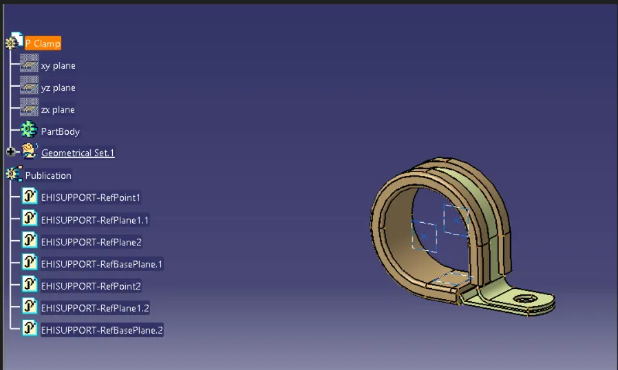
Q1. Download following cad data & define it as Electrical support using Electrical Part design Workbench. Define all the necessary properties.
Download the CAD file from given link and import the file into CATIA V5.
Add centre points by using point option on both side of clamp which we can consider as entry and exit cables.
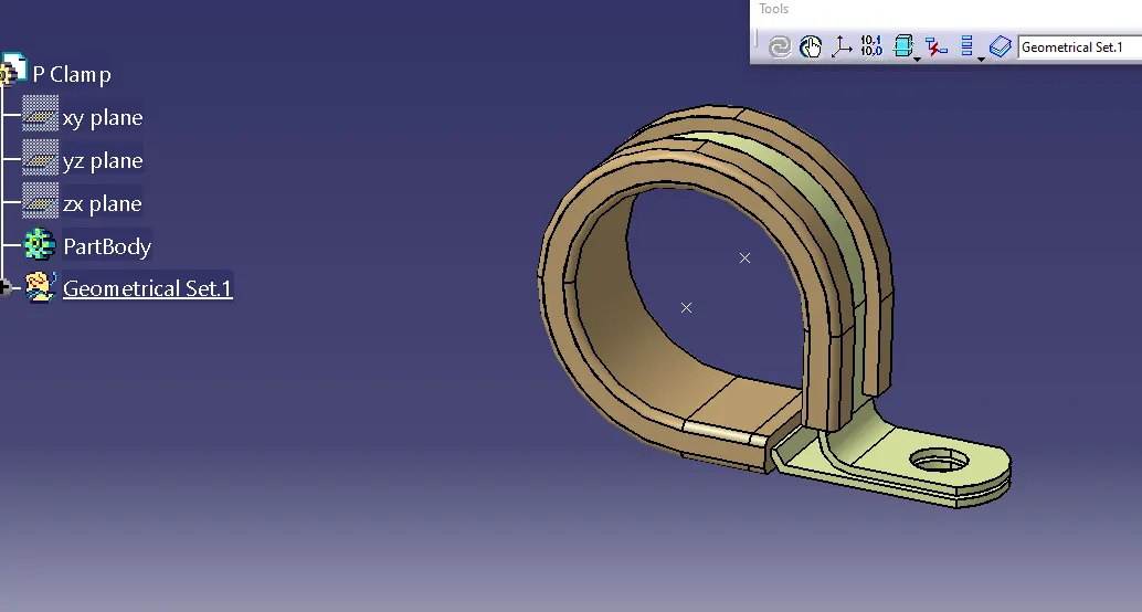
Add planes by using plane option on both side and also add base plane as shown below image.
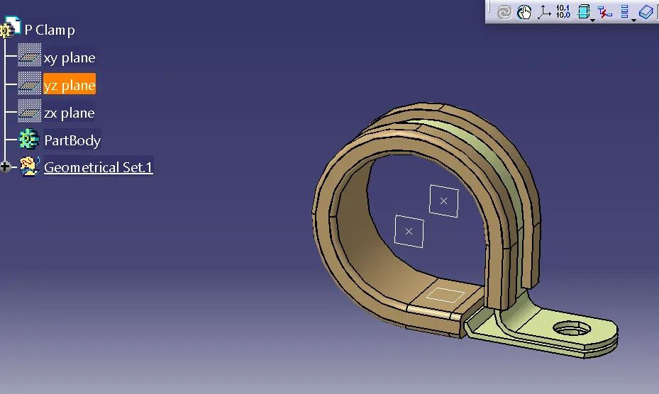
Lets move to electrical part design in which we can add all electrical properties.
defining it as Support part as shown.
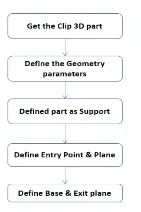
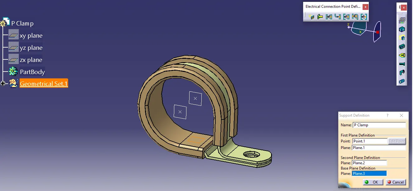
All properties were defined as shown.
Q2. Download following Back shell cad data & define it as Electrical back shell using Electrical Part design Workbench. Define all the necessary properties.
Download the backshell from given above link and import to CATIA V5.
create point of system on both side as below.
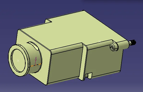
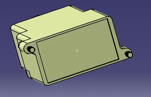
add axis system on both side.
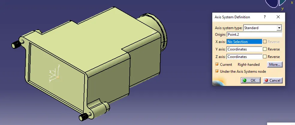
now move into electrical part design workbench.
define it as a back shell using backshell option
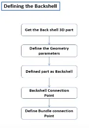
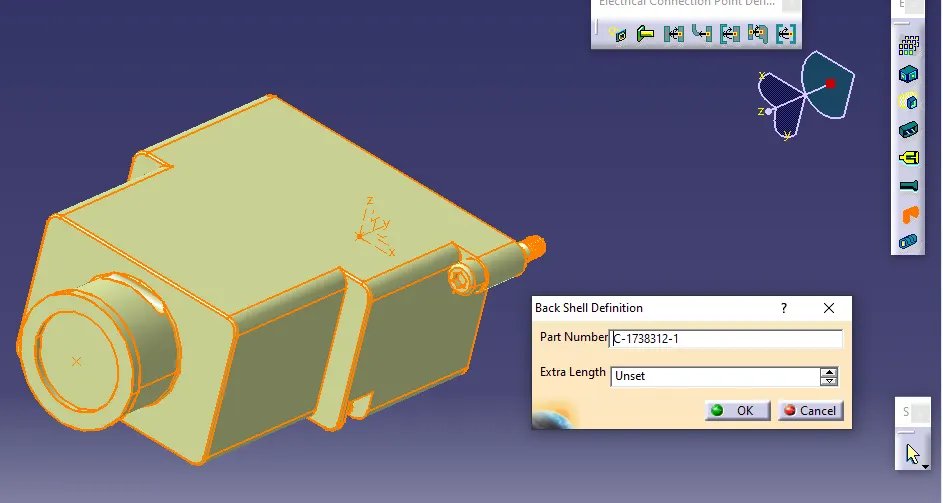
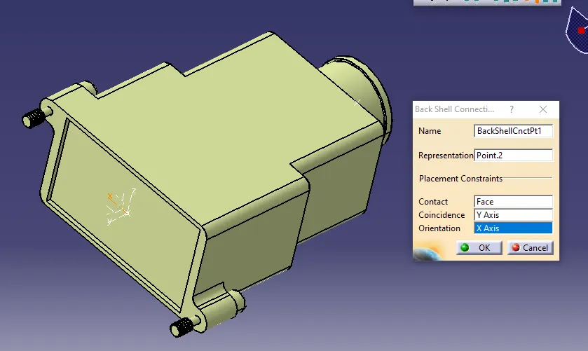
defining it as backshell connection point as below.
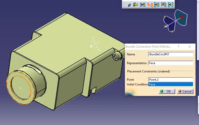
Defining it as bundle connection point.
Q3. Create Following Corrugated tubes & Add them in Catalogue under “Slit COT” family.
|
Name |
ID (mm) |
OD (mm) |
Thickness (mm) |
|
15mm COT |
12 |
15 |
1.5 |
|
20mm COT |
17 |
20 |
1.5 |
|
35mm COT |
32 |
35 |
1.5 |
|
10mm COT |
7 |
10 |
1.5 |
|
5mm COT |
3 |
5 |
1 |
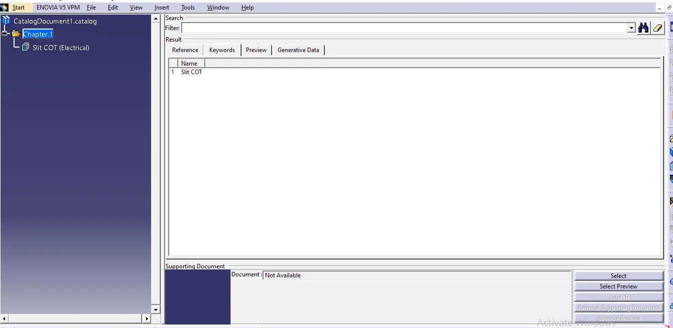
Catalogue document has created as below.
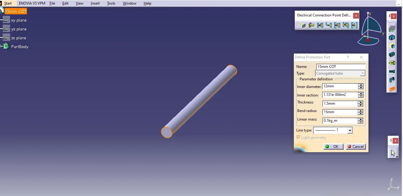
corrugated tubes are created as below methods.
corrugated tubes are created in electrical part design workbench.
select tubes from the workbench and update the values as given above.
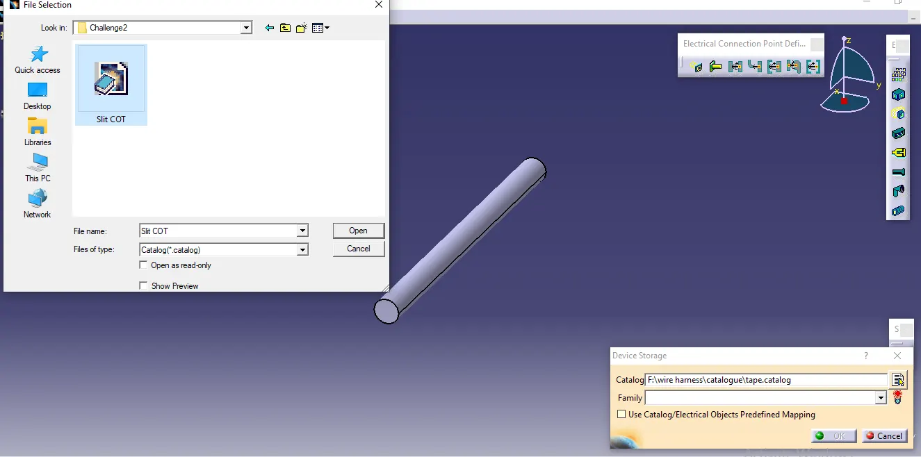
 By use of store device option we can save all tubes in catalogue.
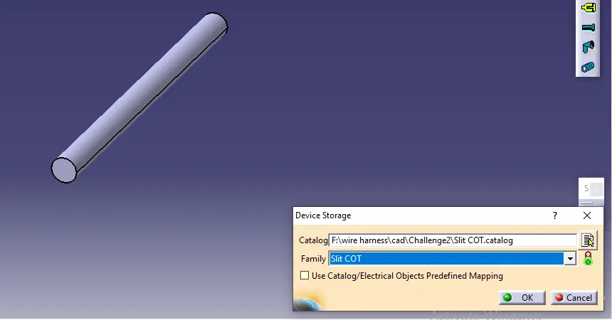
By using same method ww have created 20mm COT, 35mm COT, 10mm COT and 5mm COT tubes.
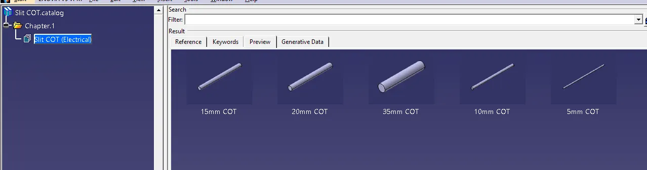
All types tubes are saved in Catologue.