Project 2
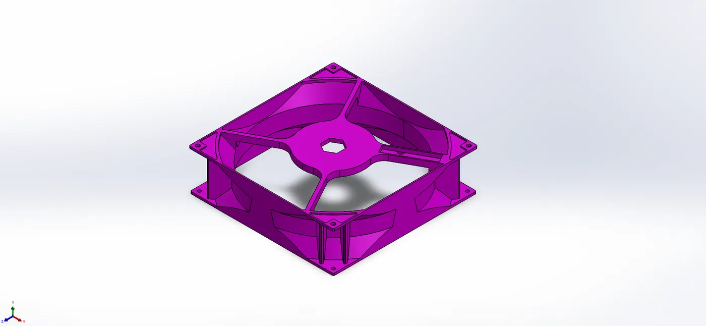
CPU Fan Bezel MOLD ASSEMBLY DESIGN:
INPUT:
OUTPUT:
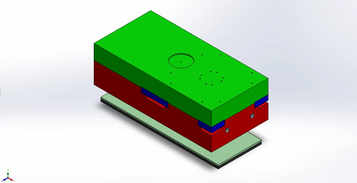
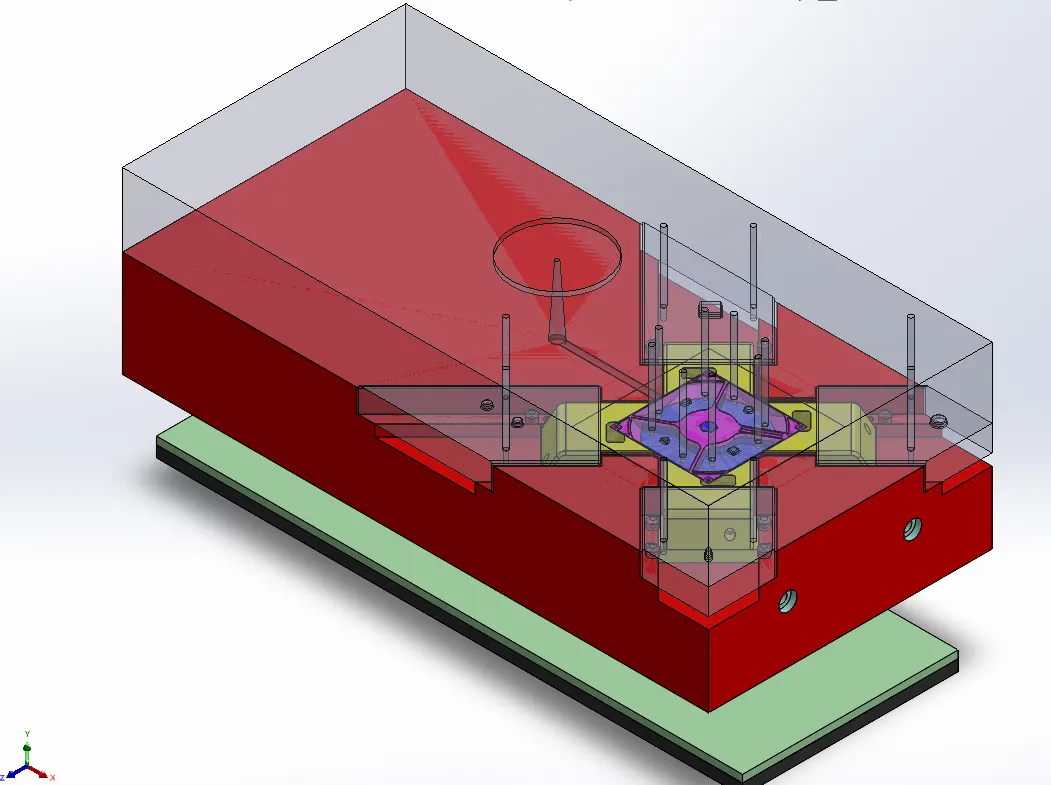
The procedure for achieving the output included creation of
- Core and Cavity surface bodies
- Core and Cavity Blocks
- Sliders
- Inserts (on both core and cavity side)
- Ejection system i.e. Ejector pins, ejector plate and support plate.
- Sprue, Runner and Gate system.
- Cooling channels
- Air vents
CORE AND CAVITY SURFACE BODIES:
In CPU Fan Bezel part,
- Part is scaled using SCALE command by 0.6% (for ABS) for shrinkage allowance.
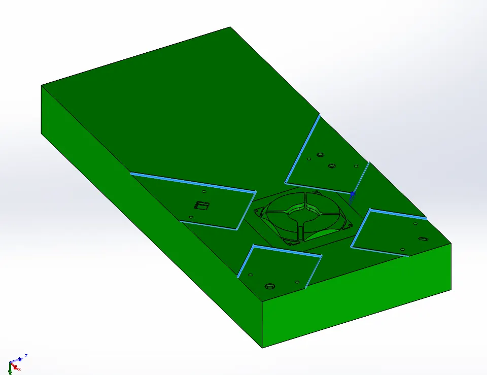
Also, using PARTING LINES command parting line (in blue) is made by giving input of face normal to tooling direction.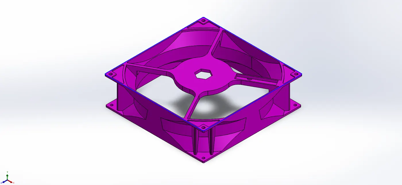
- PARTING SURFACES command is used for creating parting surface of 200mm on each four sides.
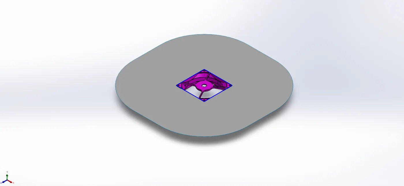
- The mold is separated into core and cavity surfaces with SHUT-OFF SURFACES command.
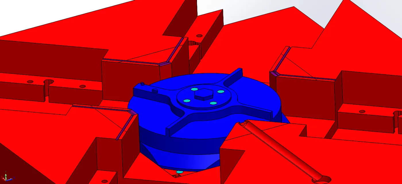
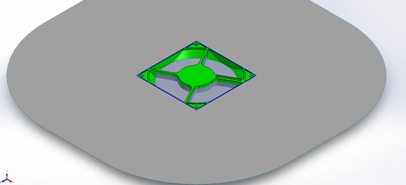
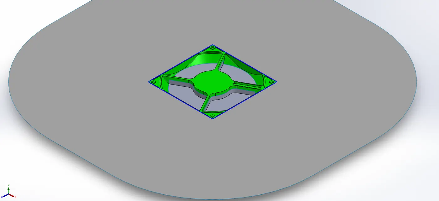
Some regions are shut-offs as No fill because the default surfaces created is not as per requirements (as can be seen from empty spaces in green colored cavity surfaces).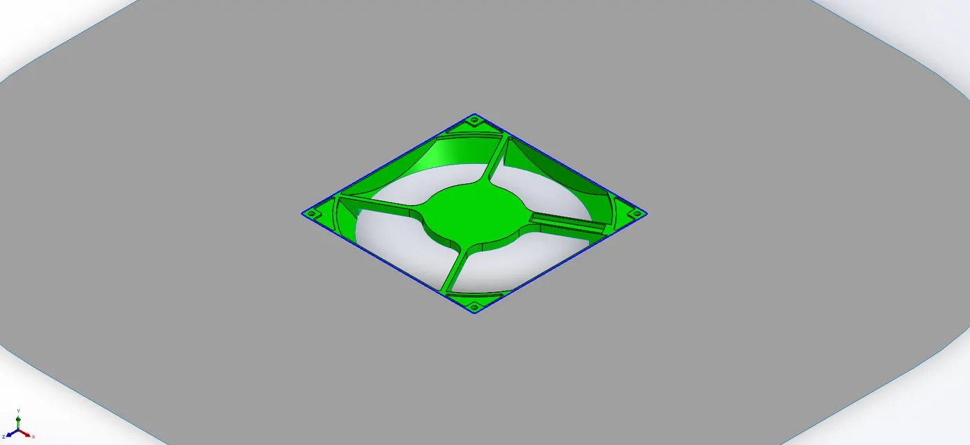
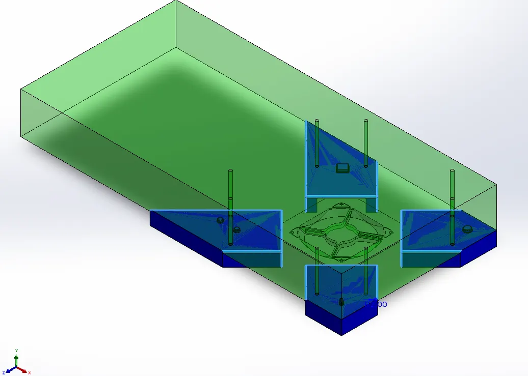
- For obtaining the surfaces as per requirement, RULED SURFACES (in 1st Picture below) and LOFTED SURFACES (in 2nd Picture below).
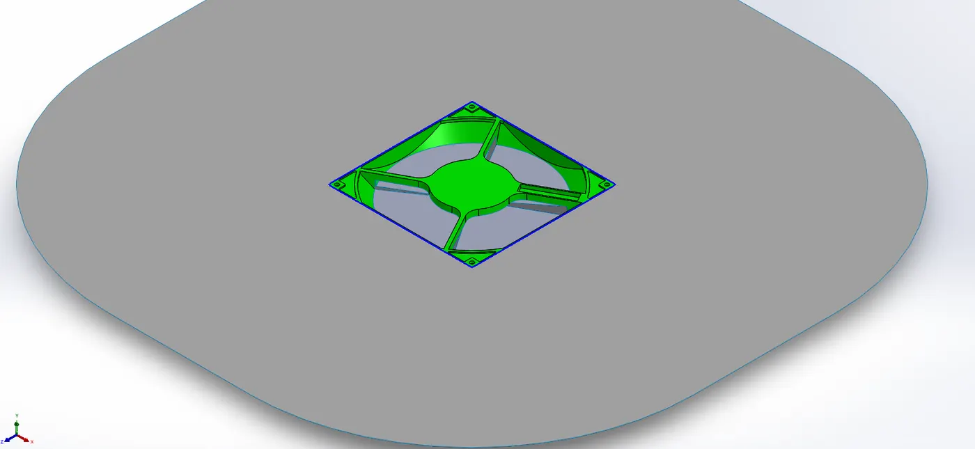
- Using EXTEND SURFACES command to extend the edges of surfaces so that they can be trimmed properly using TRIM SURFACES command.
- The four surfaces and Parting surfaces are duplicated using MOVE/COPY BODIES command.
Each set of these surfaces are then joined to core and cavity surfaces obtained in Step 3 using KNIT SURFACE command.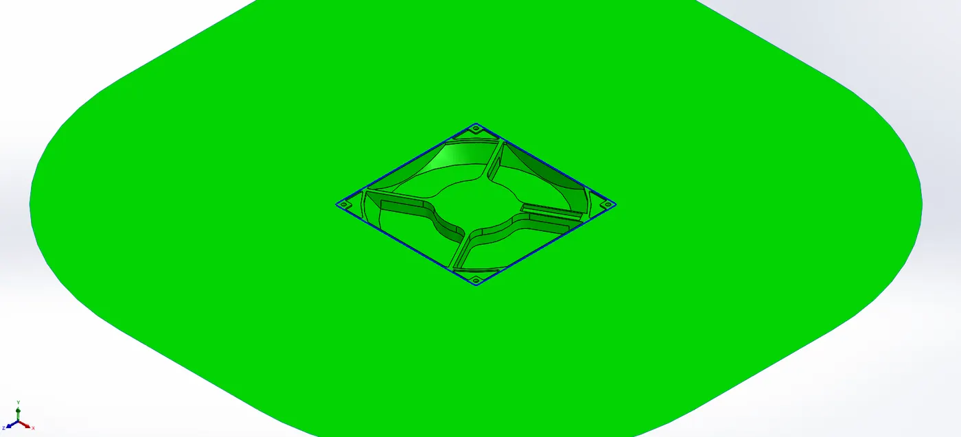
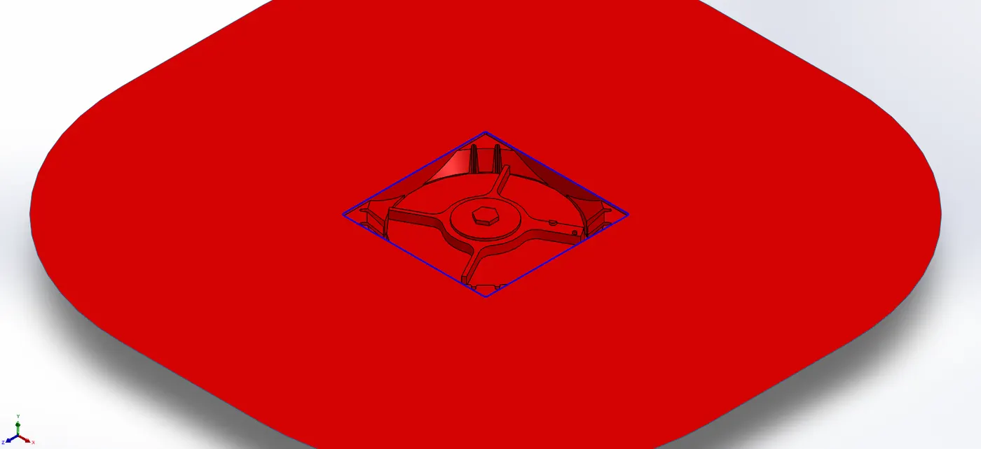
The Mold is inserted into a new assembly.
The assembly is adjusted to be in line with parting surface and distance between right planes of CPU fan bezel part and assembly be 200mm in direction of X-axis.
Two new parts are inserted into the assembly, i.e. Core steel and Cavity steel.
CORE AND CAVITY BLOCKS:
In Cavity Steel,
- Cavity surface is copied from mold part using OFFSET command.
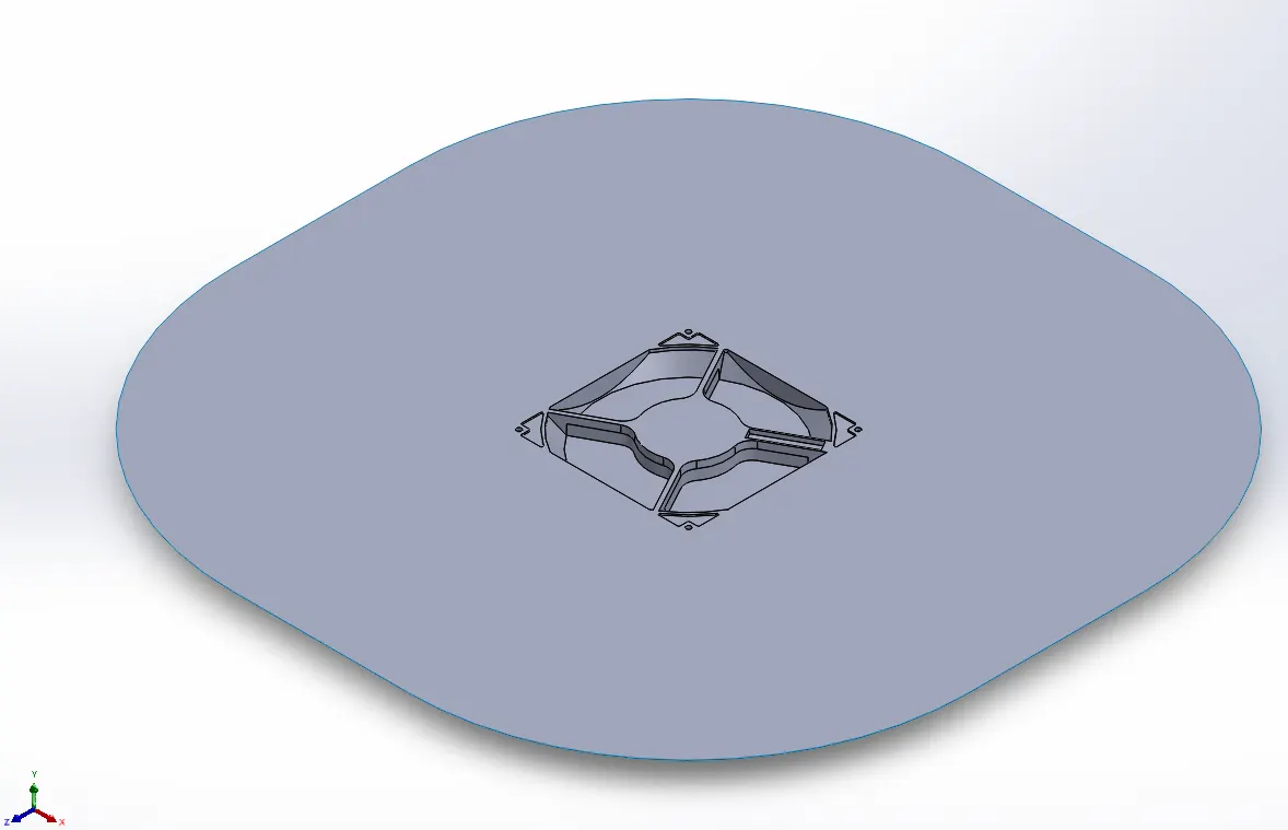
- Sketch is made for construction of Cavity Block using EXTRUDED BOSS/BASE command.
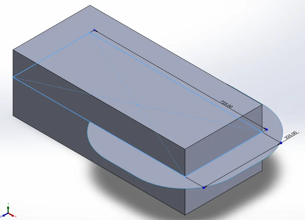
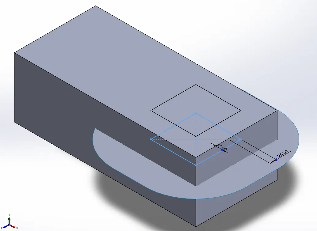
- Another sketch having 25mm clearance all around with the part is made. The block is then splitted using this sketch by SPLIT command.
- The inner body is then cutted with cavity surface offseted in step1 using CUT WITH SURFACE command.
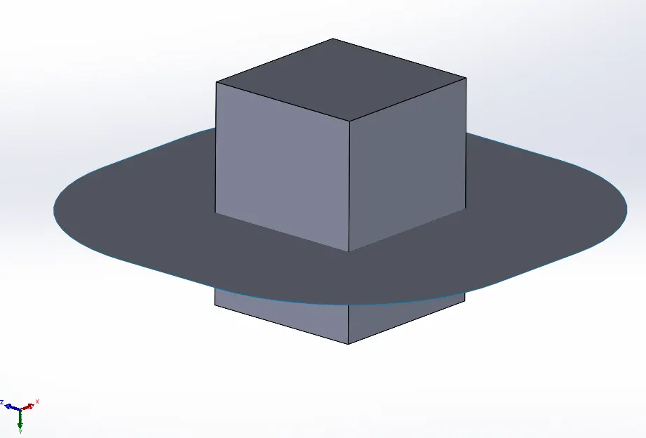
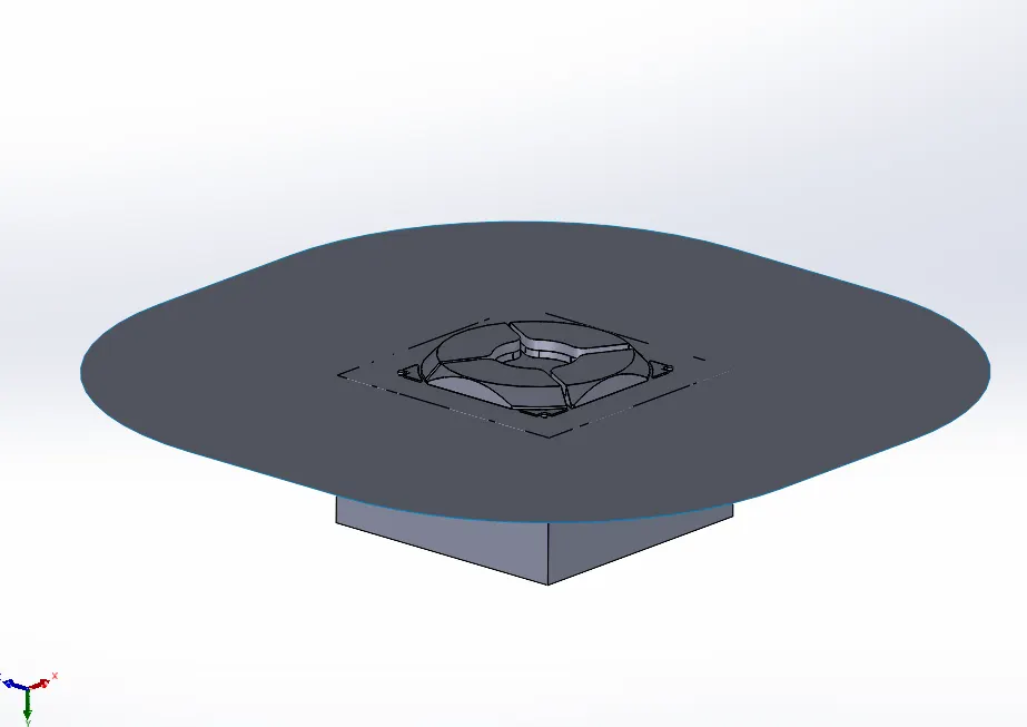
- Now the outer block is trimmed to be in line with the inner block using MOVE FACE command.
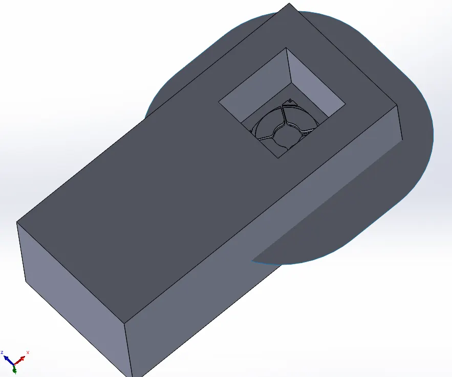
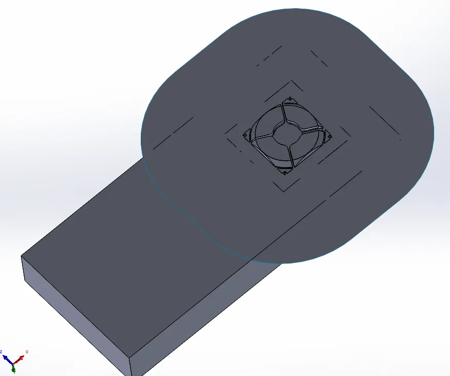
- Both blocks are joined to form Cavity block using COMBINE command.
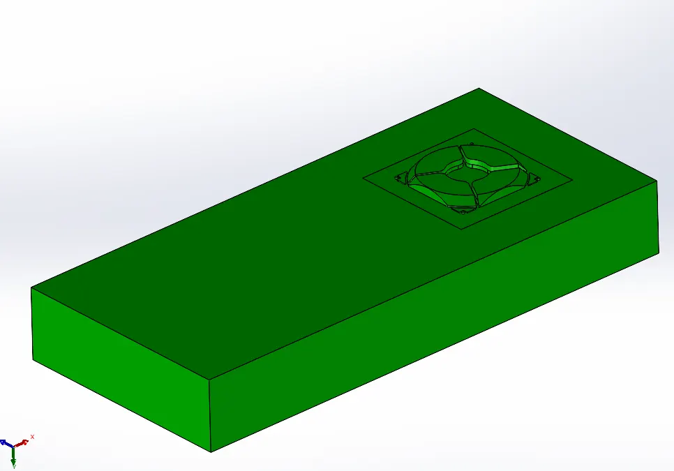
In Core steel,
Similar procedure is done as cavity block. In place of cavity surface, core surface from mold part is duplicated and block is cutted by it.
Also, same sketch were copied using CONVERT ENTITY command in sketching window.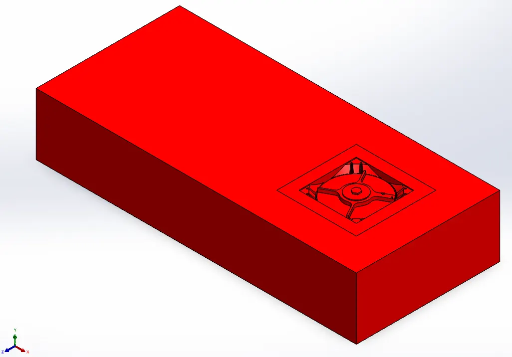
SLIDERS:
In Core Steel,
Since majority of part lies in Core block, and also undercut regions also lies in core side. Therefore, sliders bodies are splitted from core block.
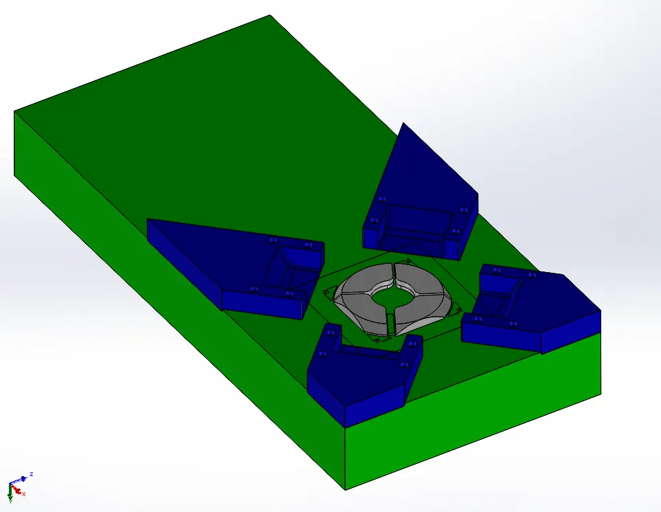
- Sketch is made for four slider bodies.
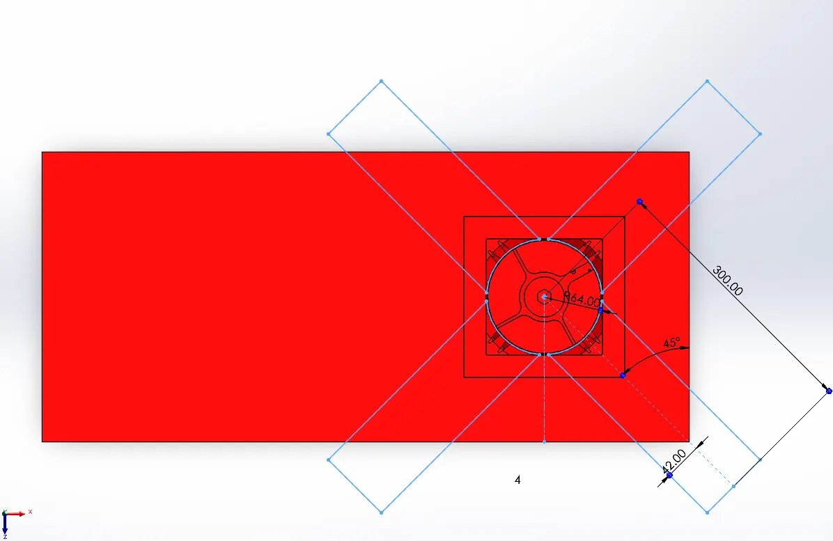
- SPLIT command is used, sketch and plane upto which slider is needed is selected for forming slider bodies (in yellow).
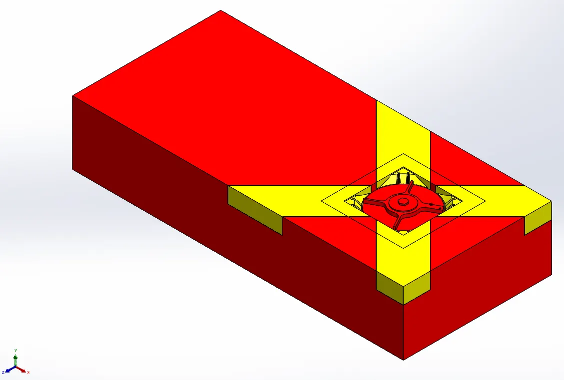
- Each slider body is then modified as shown below using EXTRUDED BOSS/BASE command and EXTRUDED CUT command.
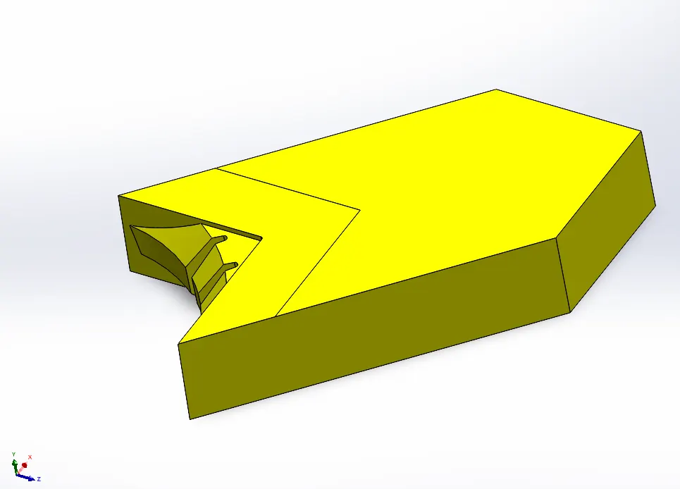
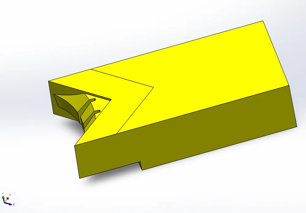
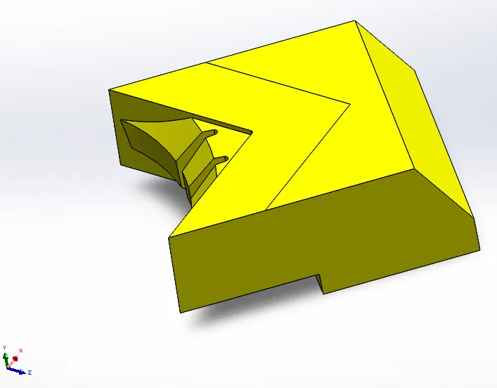
- Walls of 5mm of each side are added onto slider using EXTRUDED BOSS/BASE command.
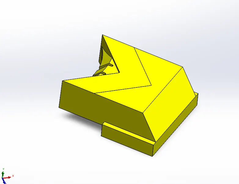
- FILLETS are added onto the slider body.
- Similar features are added onto the remaining three sliders.
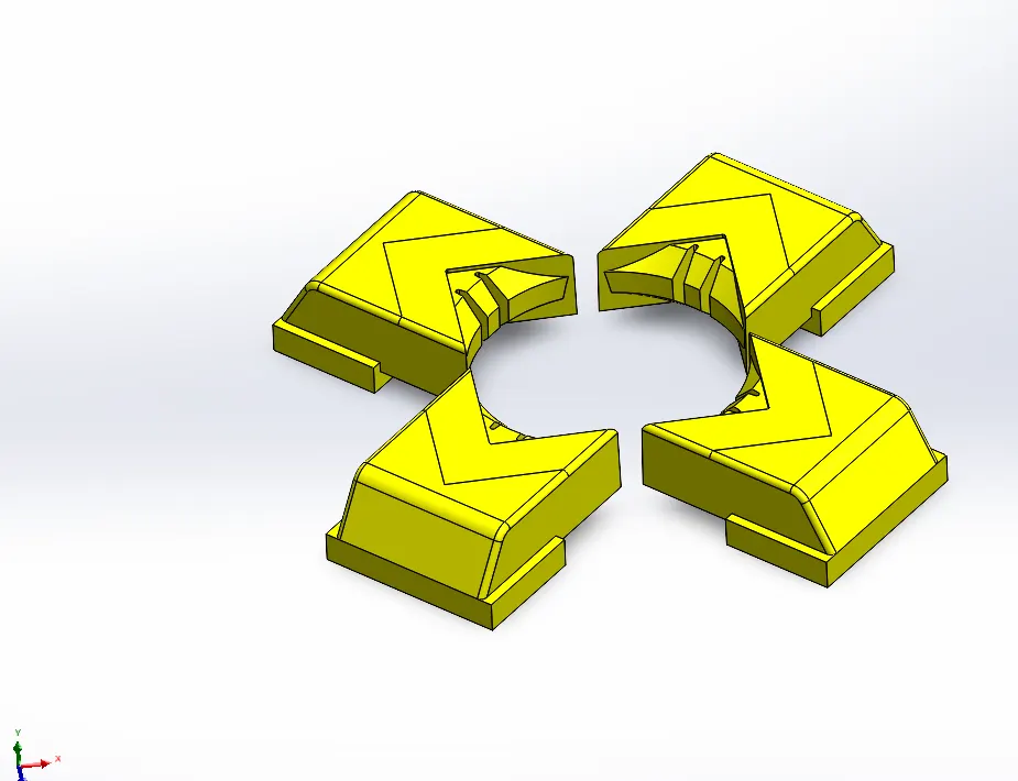
- All the slider bodies are saved as separate parasolid bodies by right clicking on body (in solid bodies) and choosing INSERT INTO NEW PART option.
- Using COMBINE command, the slider are subracted from Core block.
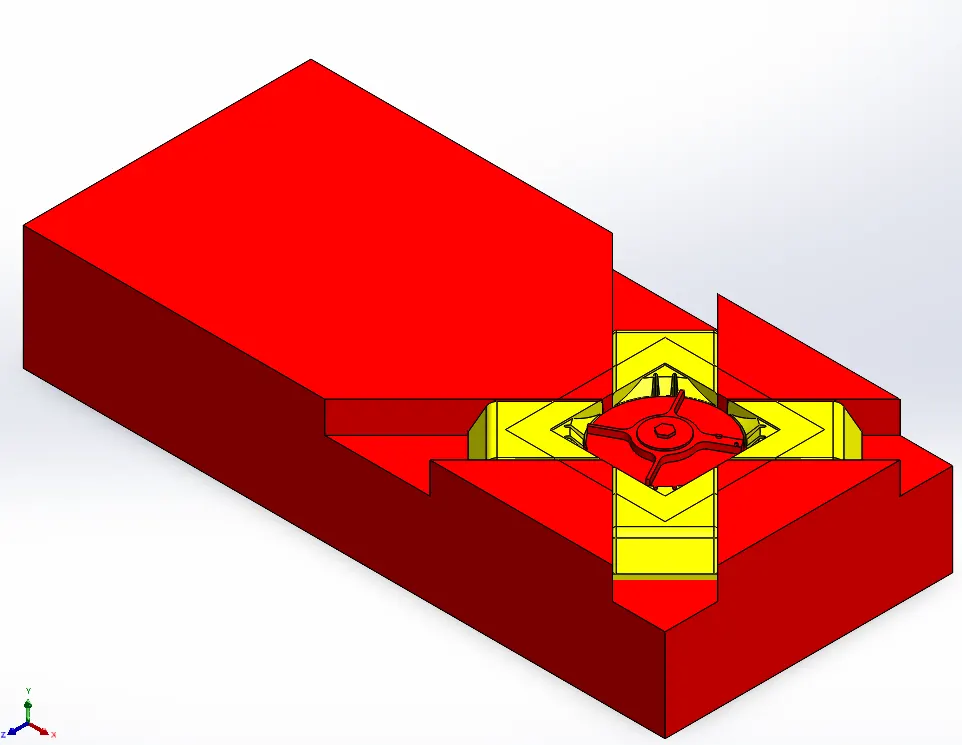
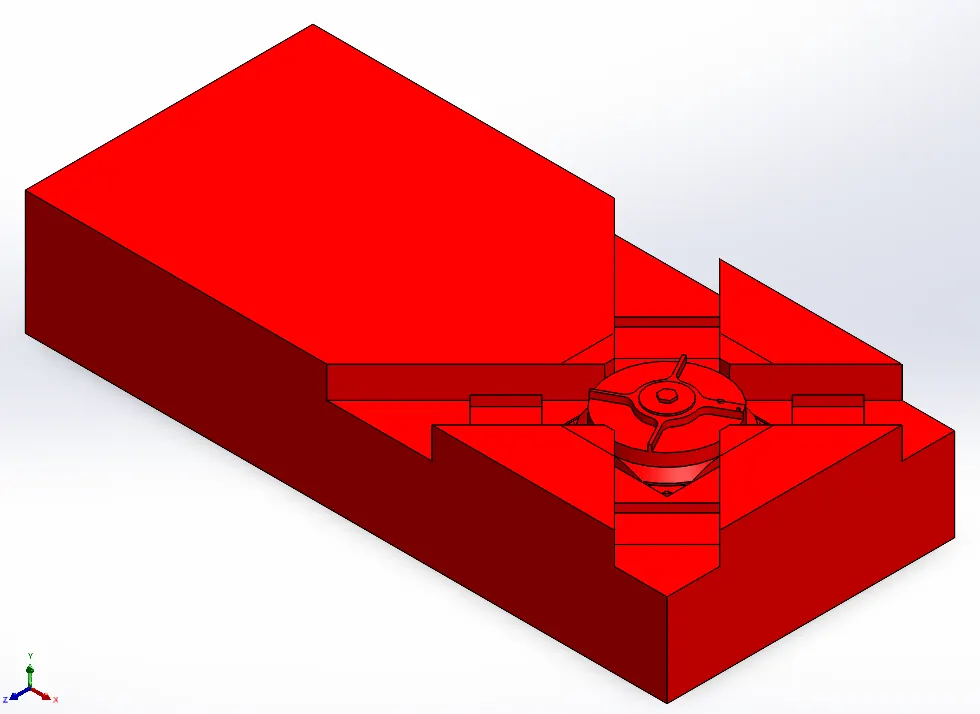
- For slider motion, material is removed from core body using MOVE FACE command.
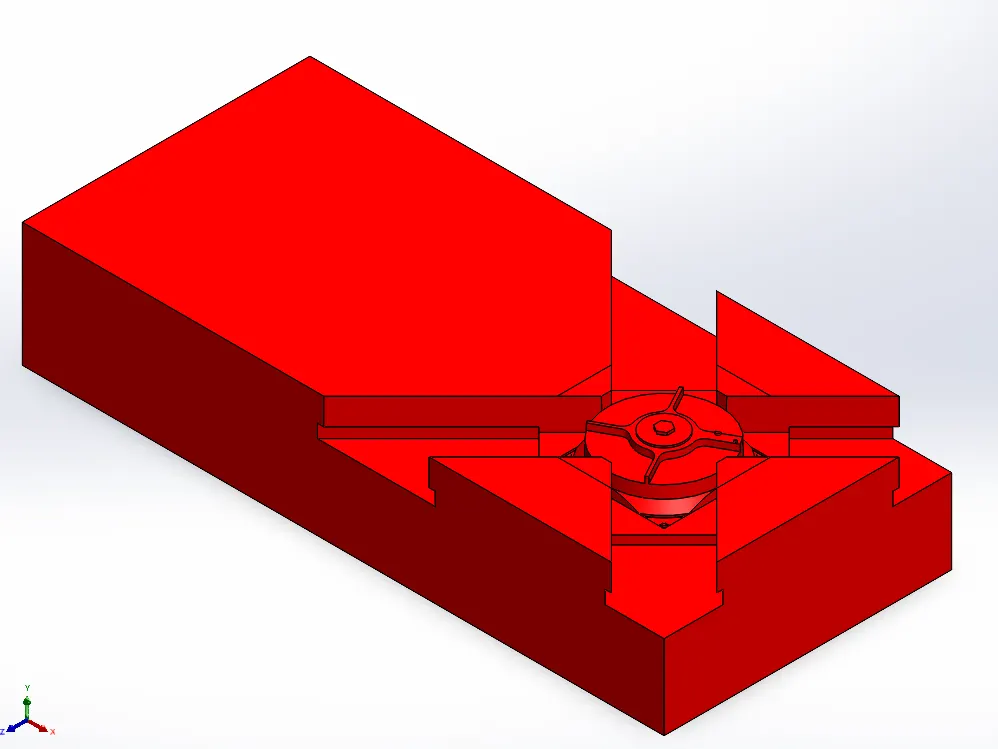
- Walls of 15mm width and height upto 30 degree surface edge are created using EXTRUDED CUT command.
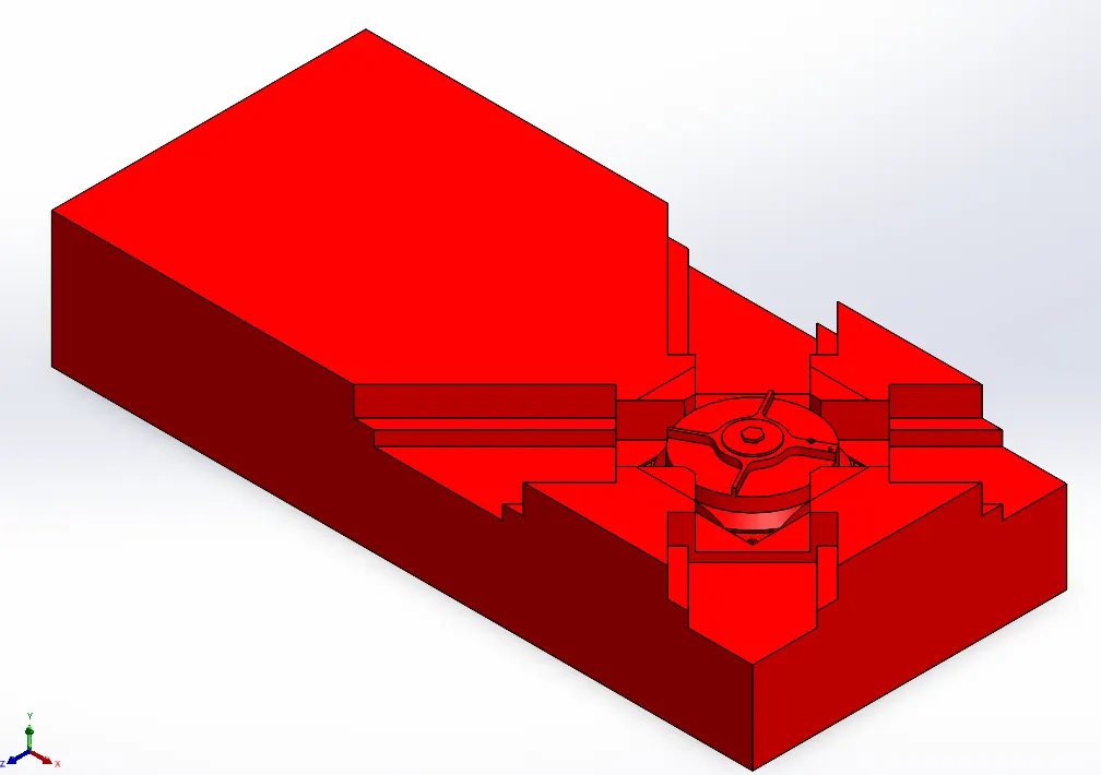
- Tapped hole is made for M6 bolts and washers to be used for constrained motion of slider.
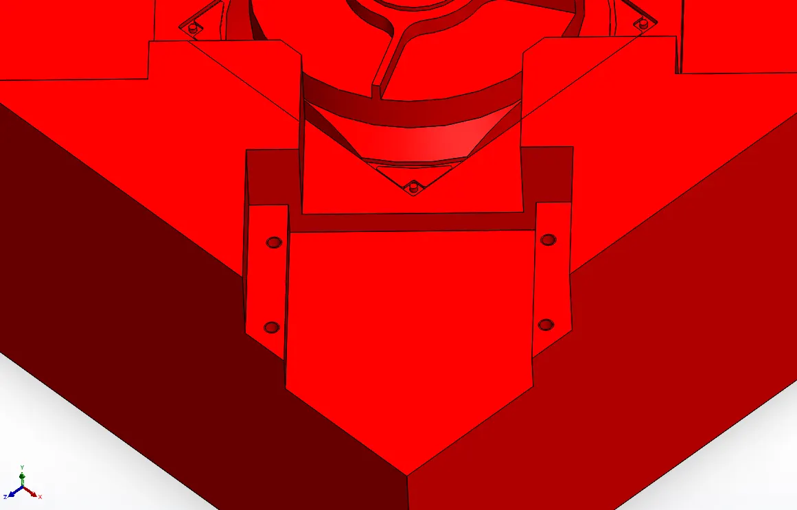
- For limiting motion of slider, slot is made using EXTRUDED CUT command. Also, fillets are done to edges of the slot.
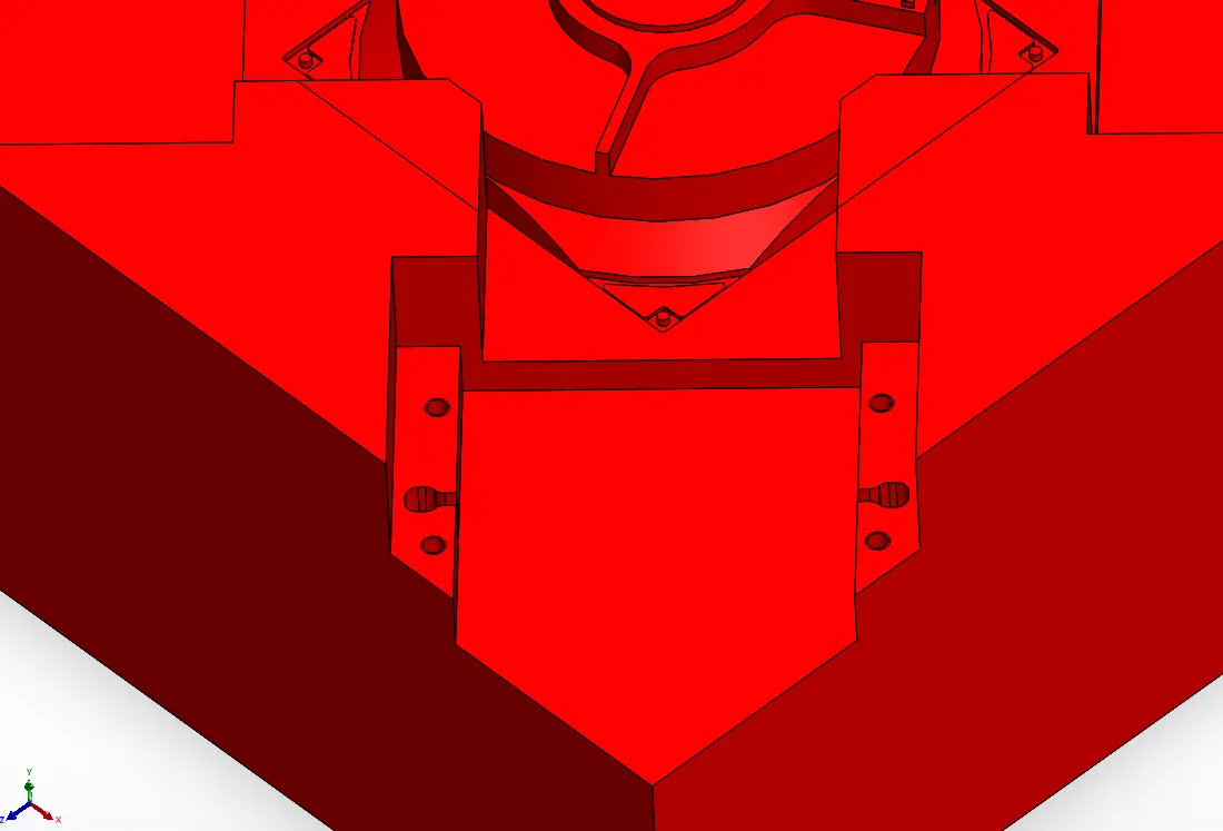
- The tap holes, slot and fillets features are then patterned across the remaining three slider walls using CIRCULAR PATTERN command.
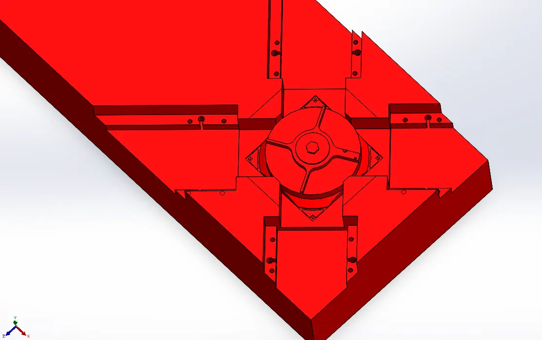
- Now at least 45mm of slider outward motion is required for safe removal to mold part during ejection process.
Hence, the block size (length and width) is increase by 25mm on each side to accomodate that, using MOVE FACE command.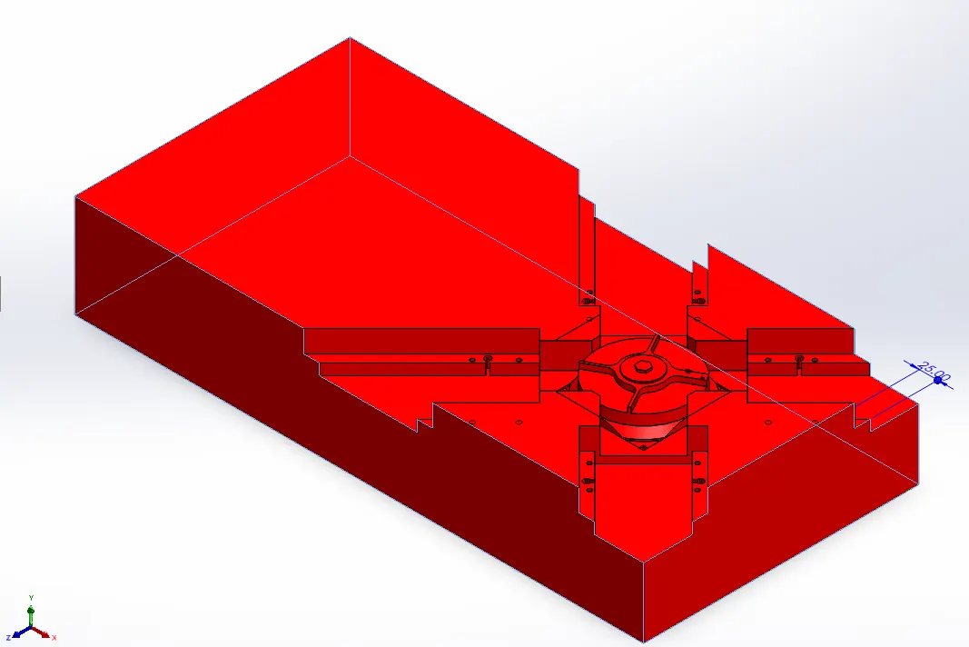
- Also Reliefs (2mm) were provided on walls were metal-to-metal contact will be present between core and cavity block.
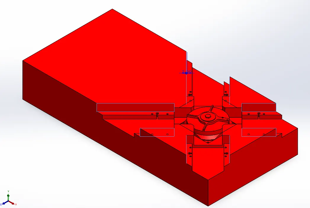
In Cavity Steel,
- The Slider bodies are imported into the Cavity block.
INSERT >> FEATURES >> IMPORTED >> Then choose the parasolid body from its saved location.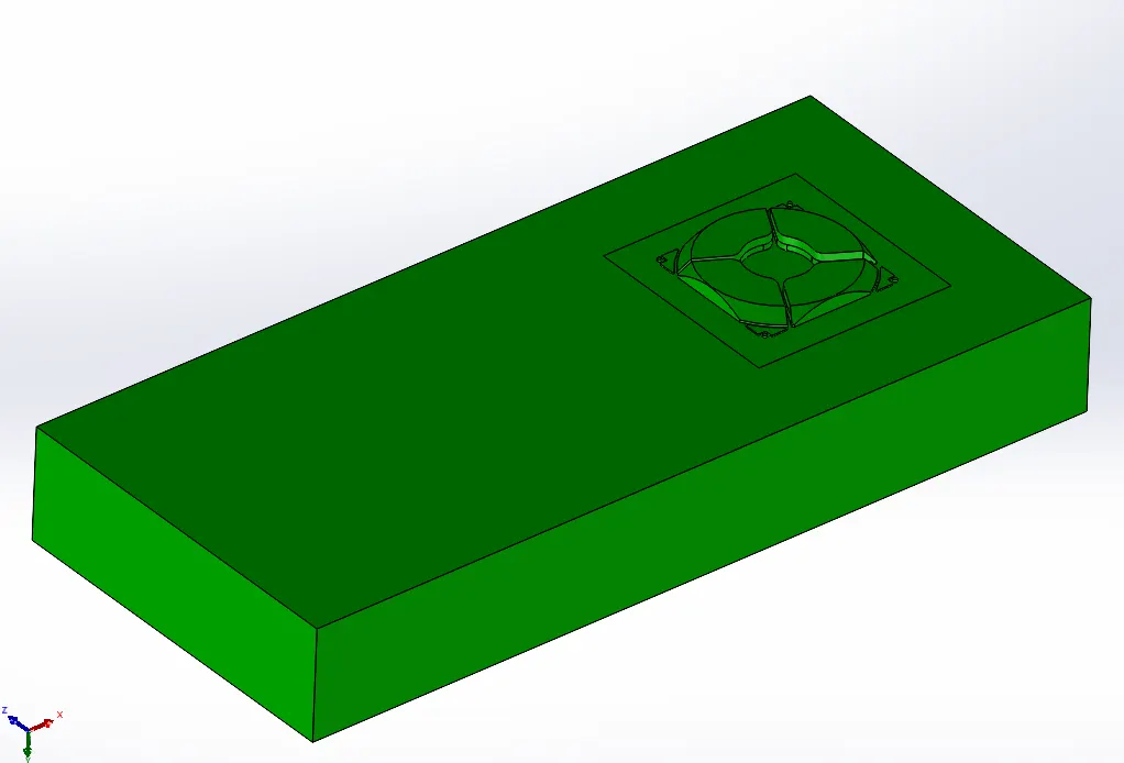
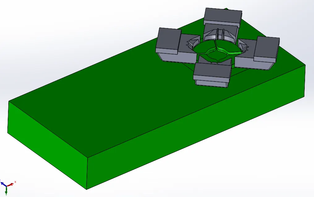
- Now material is added to the block of same thickness as size of walls in core block i.e. 15mm from slider body.
For this EXTRUDED BOSS/BASE command is used upto 2/3rd distance of slider height i.e. upto edge of 30 deg surface.
Also, this is only done upto the slider motion path only.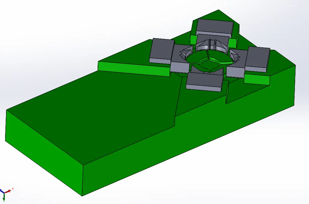
- The imported bodies are then subtracted from cavity body using COMBINE command. This is done to form exact pocket of space as required to accomodate the slider bodies.
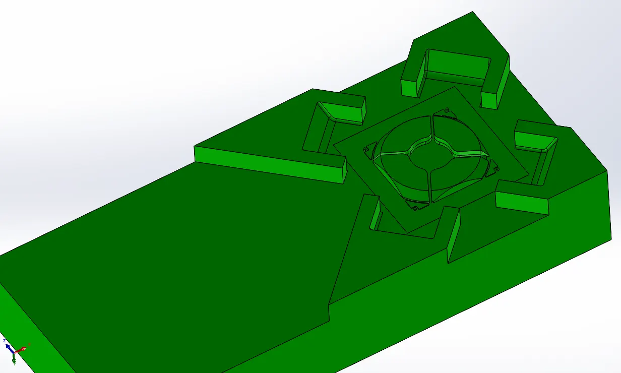
- Holes are machined for accomodating bolts head and washers. For this, 10mm deep hole with diametrical clearance of 2mm with washer is done.
Fillets are provided for ease of machining and less time consuming machining.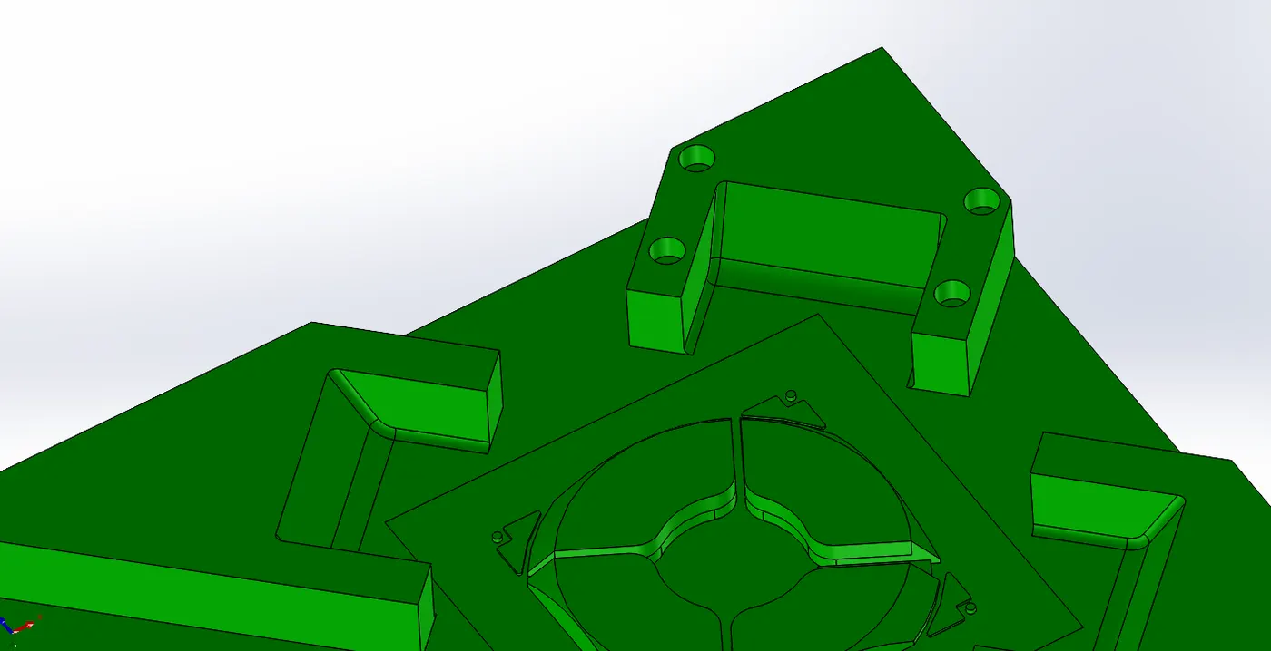
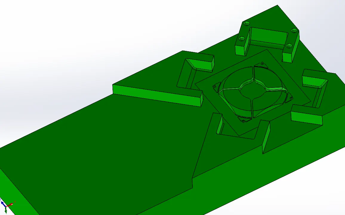
- Features in above step is then duplicated for all the cavity sliders walls using CIRCULAR PATTERN command.
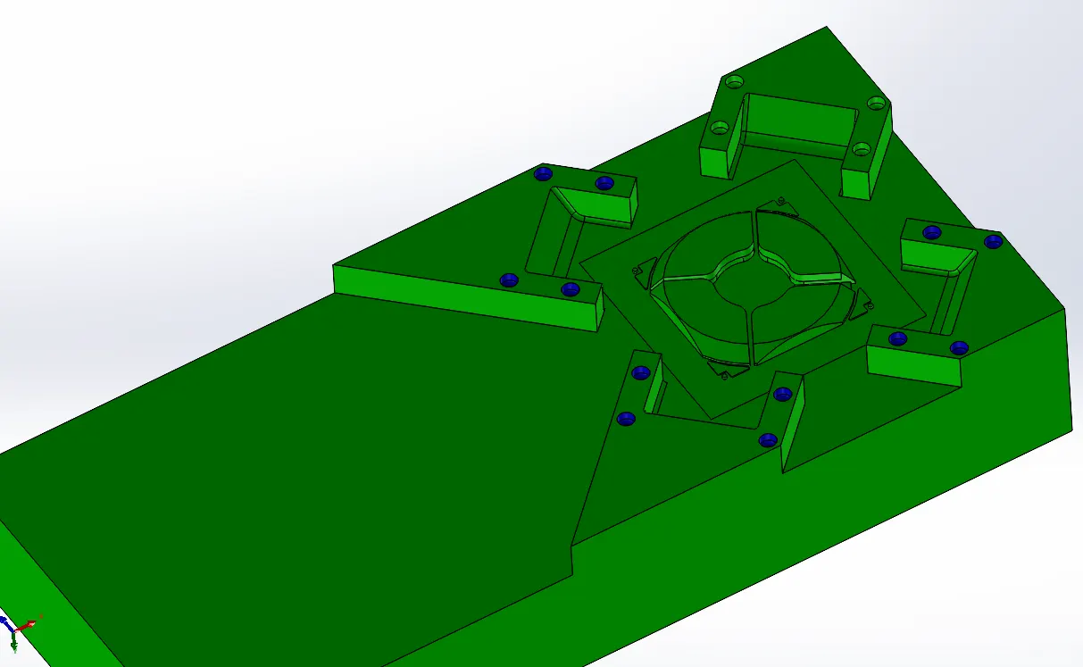
- To match the increase in size of core body the cavity block size is increased using same MOVE FACE command.
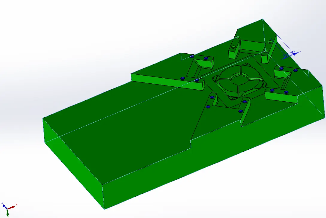
- Reliefs of 2mm were provided on the wall having metal-to-metal contact.
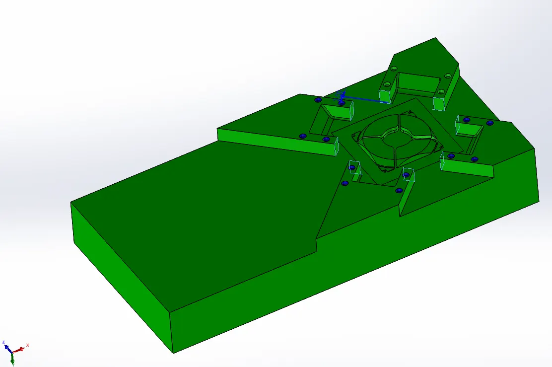
In Slider 01,
- Circular slot is made using EXTRUDED CUT command for limiting slider motion.
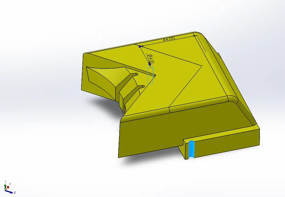
- Separate insert is made as highlighted (in dark green) for ease of machining and also eliminating need of new slider in case of wear and tear due to re-use.
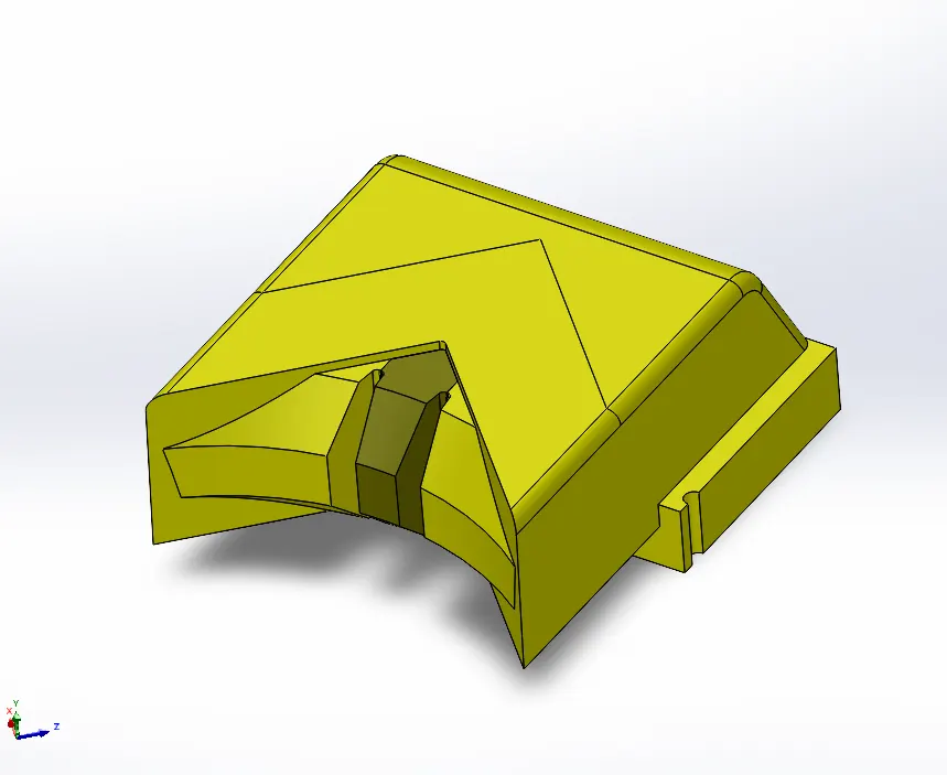
- Unsymetrical fillets are provided for elimination any mistake during assembly of the molding.
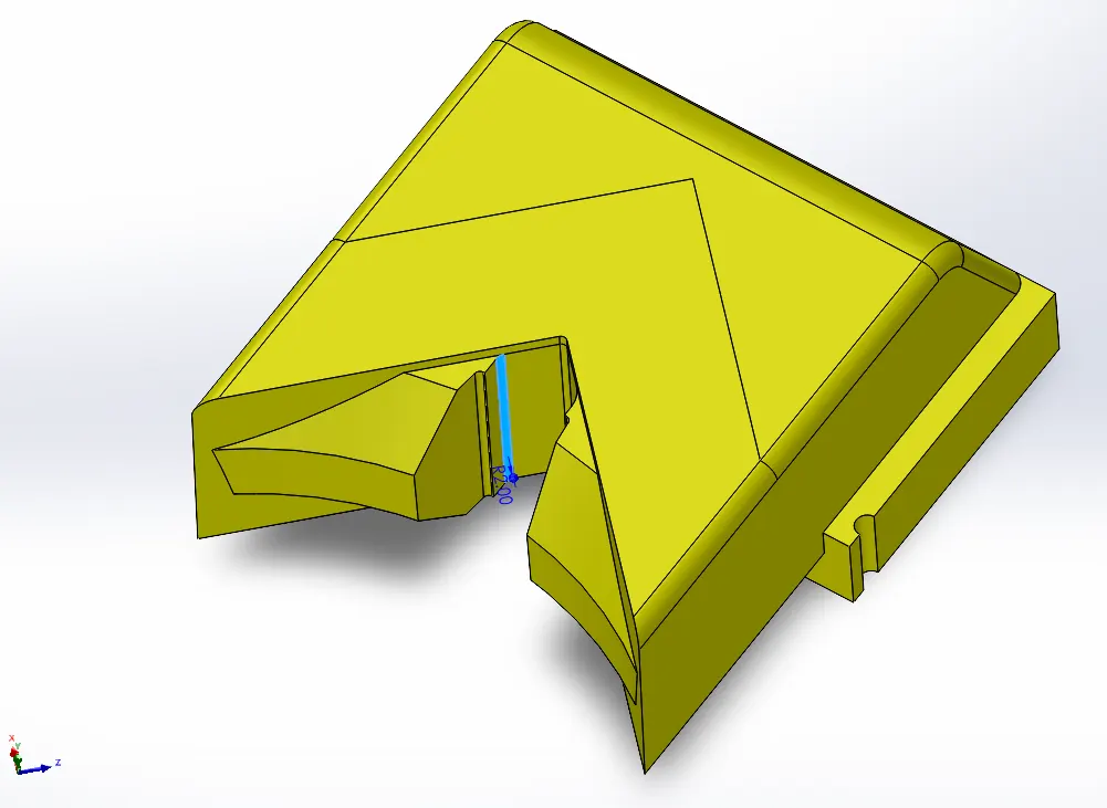
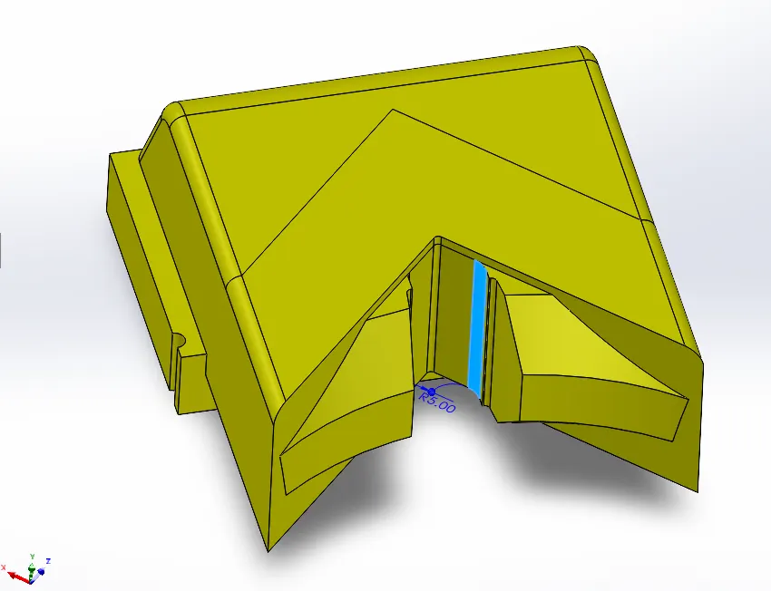
- Similar matching fillets are done for inserts also.
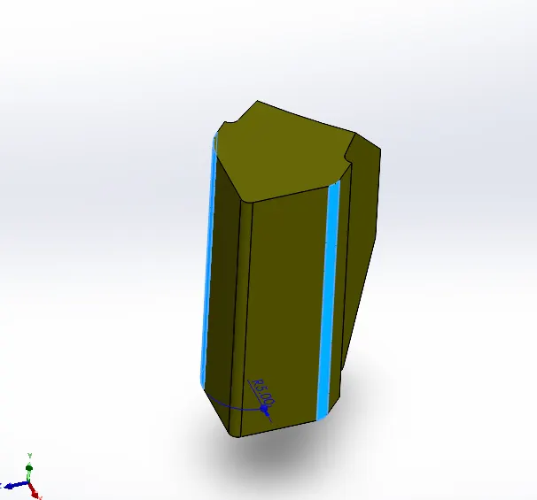
- For fixing insert body, M4 Counter Bore screw clearance hole is done on slider body.
And M4 tap hole on insert body.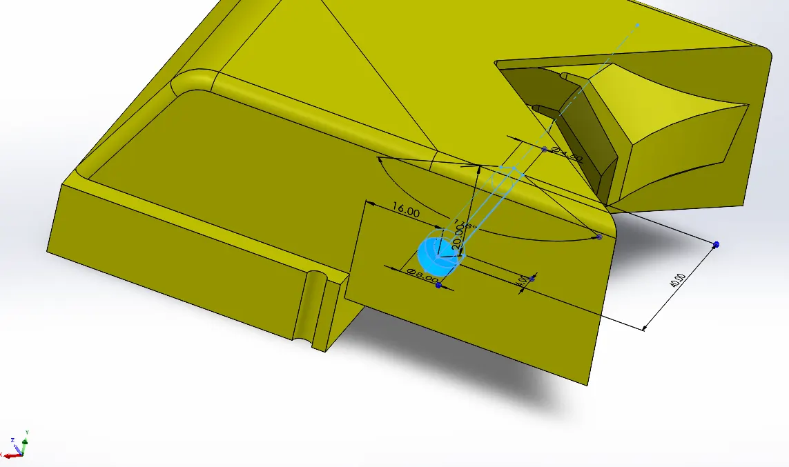
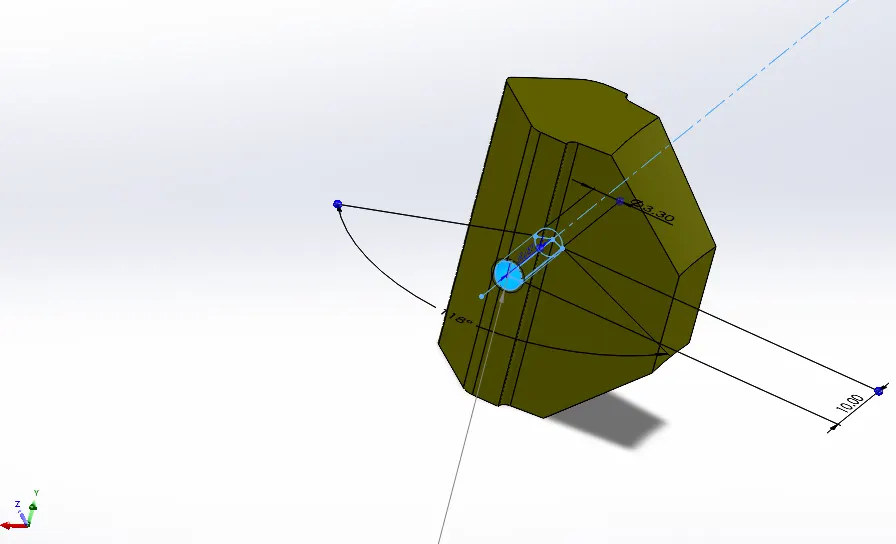
- Also filleted part of slider body is restored to edge for a distance of 20mm from slider wall starting point.
This is done so that molten metal doesnot rush between slider surface.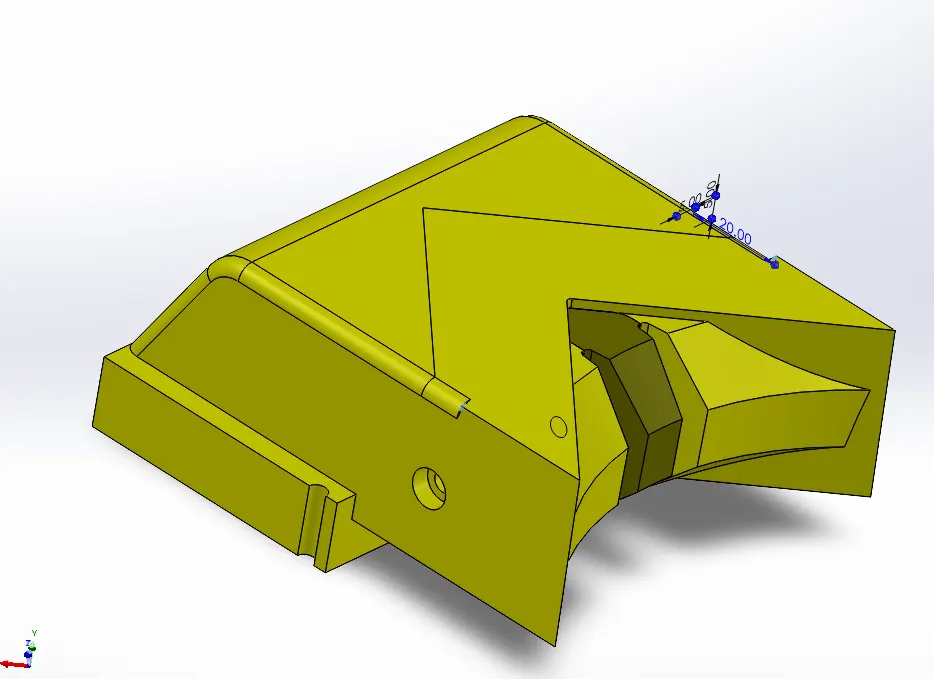
Same steps are followed for other three slider bodies.
INSERTS:
In Core Steel,
- Sketch is made for splitting insert body from Core steel.
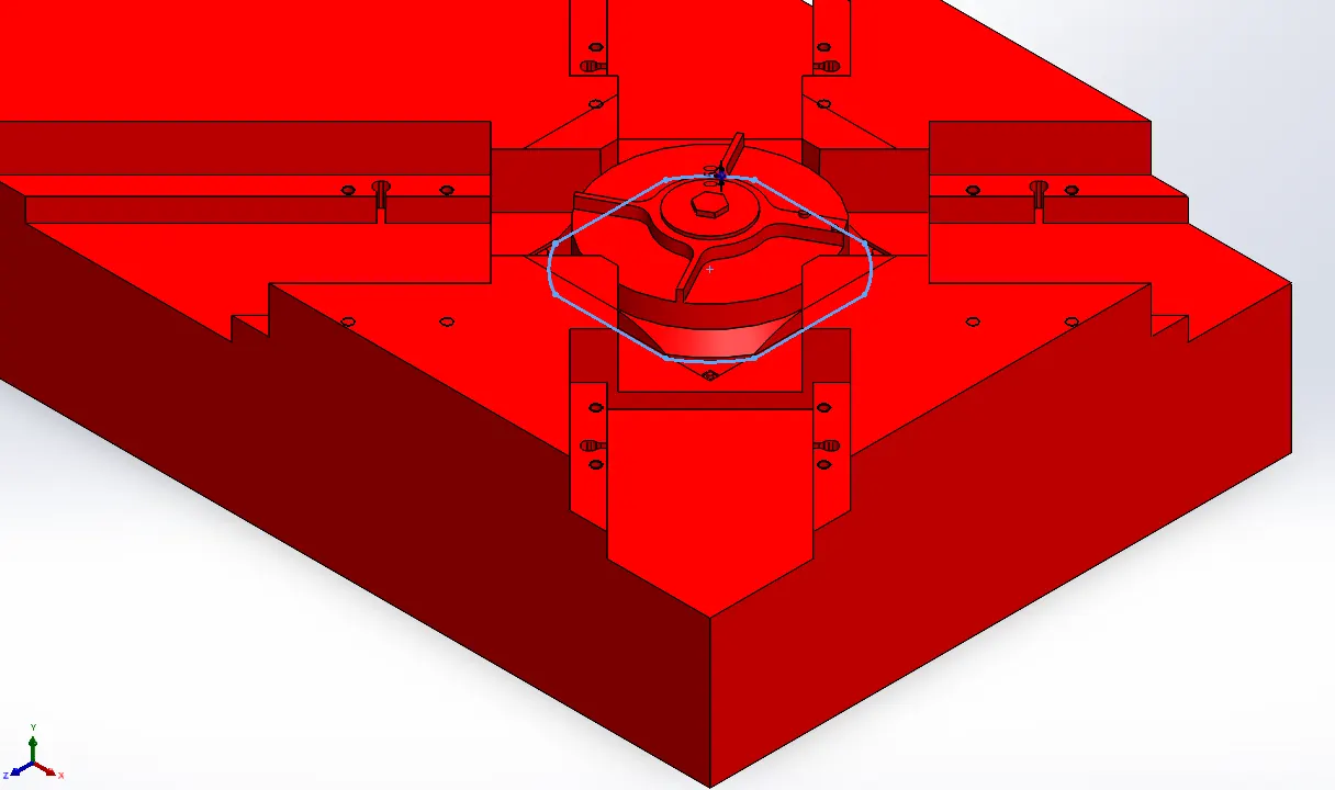
- SPLIT command is used for splitting the main central features body.
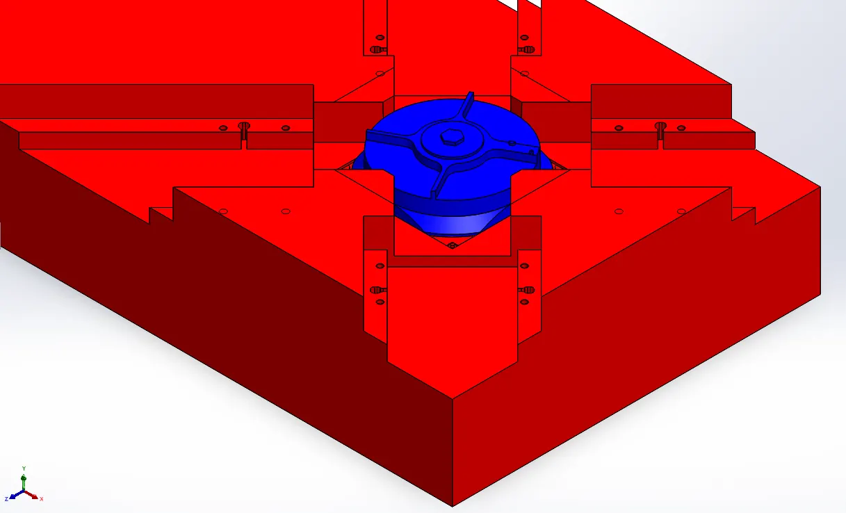
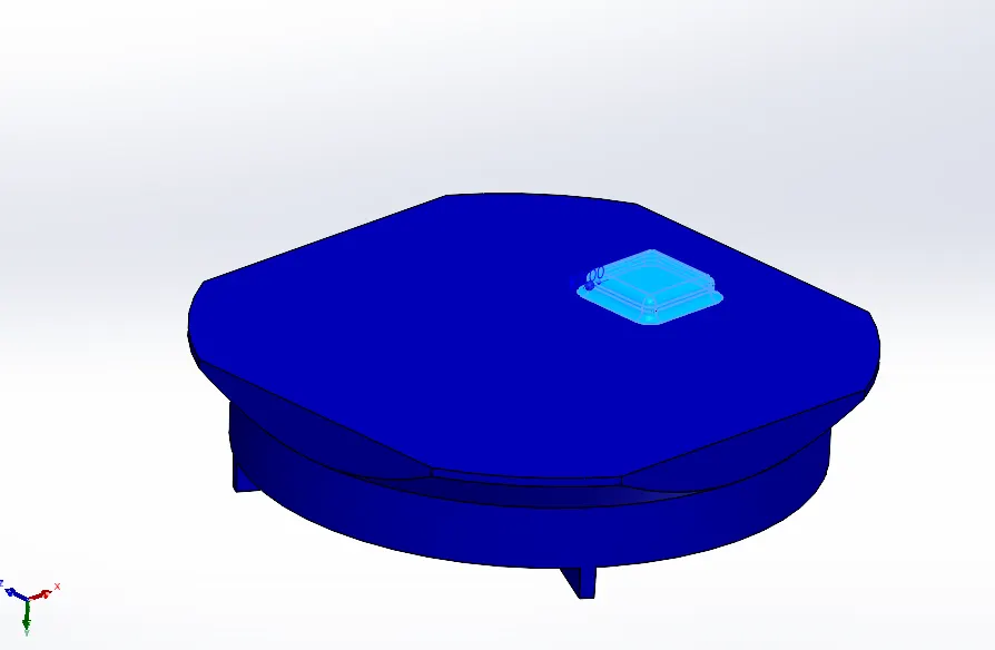
- A small raised feature is made on bottom surface of the insert, so that the alignment and orientation of the insert is as intended.
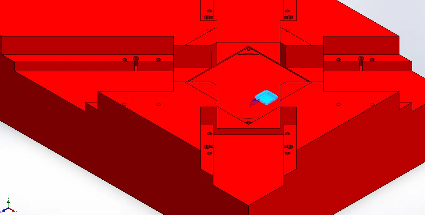
- Matching depressed feature is cutted onto the core block.
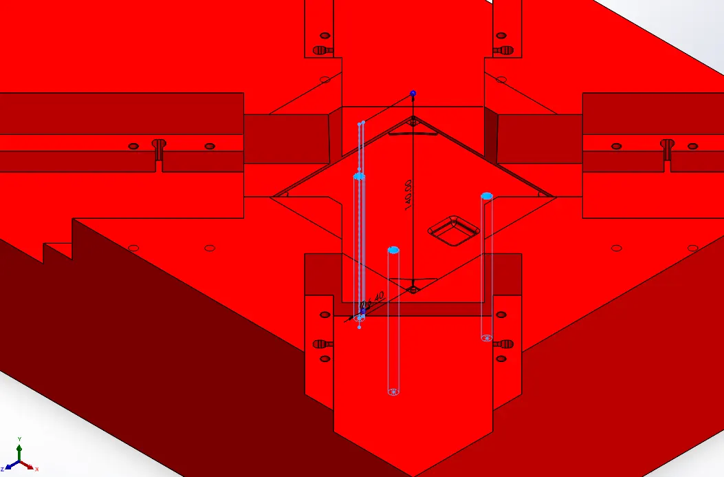
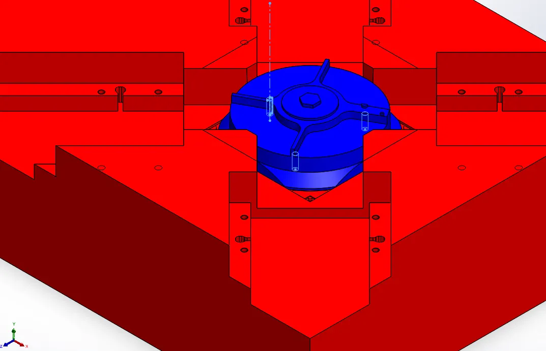
- For fixing insert, M6 through clearance hole on core block and M6 blind tap hole on Insert is done.
EJECTION SYSTEM:
In Core Steel,
- Ejector pins are formed from core body using CORE command. 8 pins are formed in total.
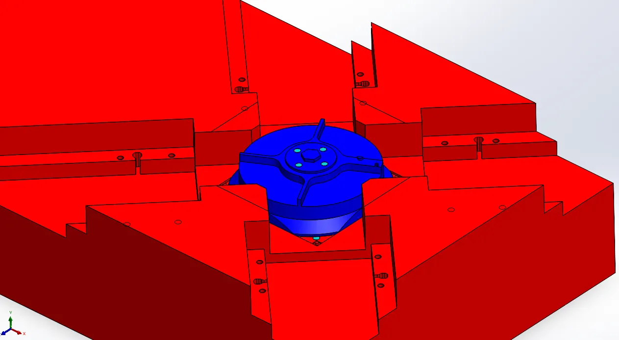
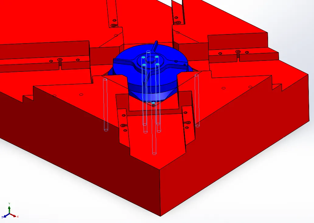
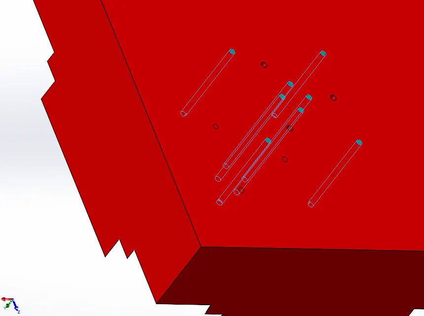
- Relief of 6.95mm for 6mm dia pins are provided from 12mm distance from starting plane.

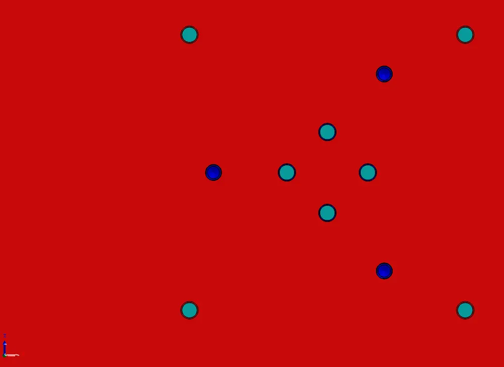
- Length of pins are increased by 100mm (stroke required for complete ejection of part).
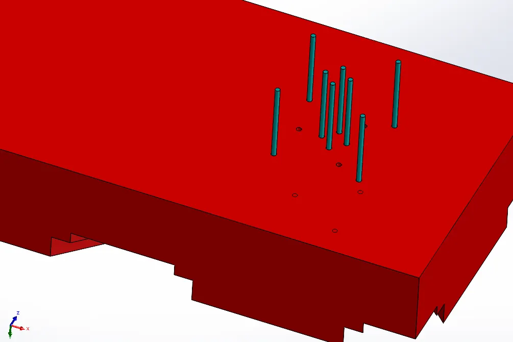
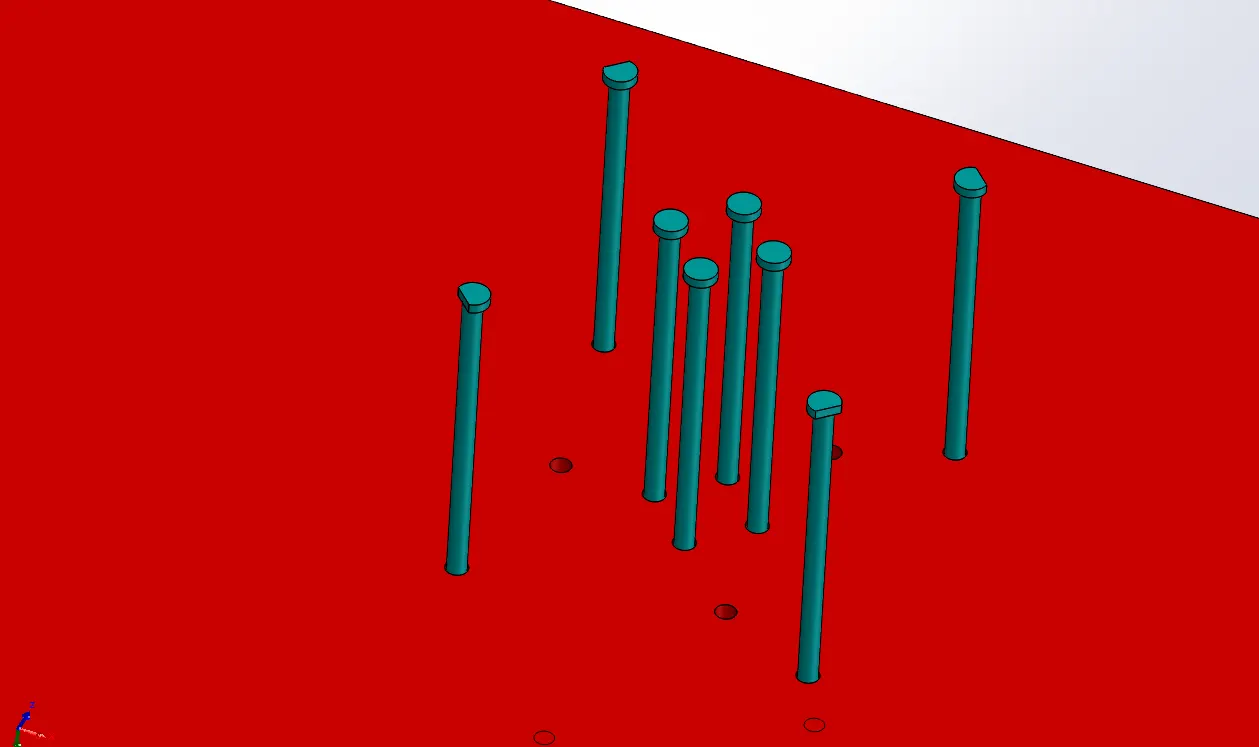
- D-shaped head of 10mm diameter is made for Four outer pins.
And Circular head of same 10mm dia for inner pour pins.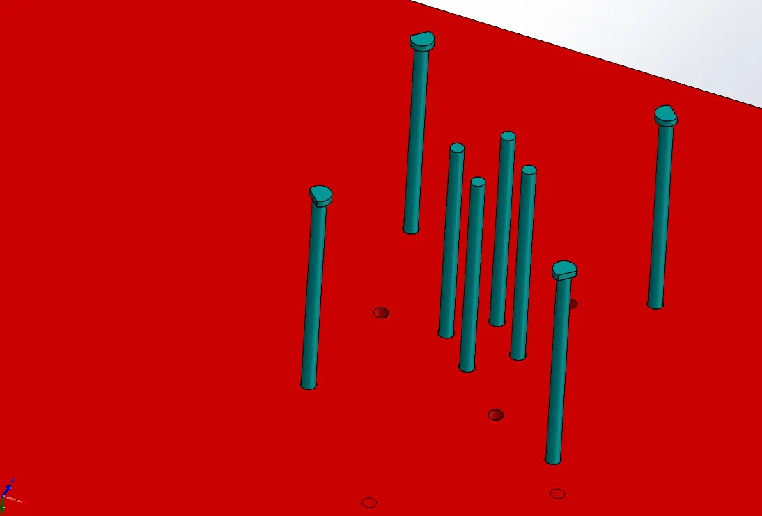
- Ejector plate of 10mm thick is made of same length as core block, but with offset of 45mm on each side of width.
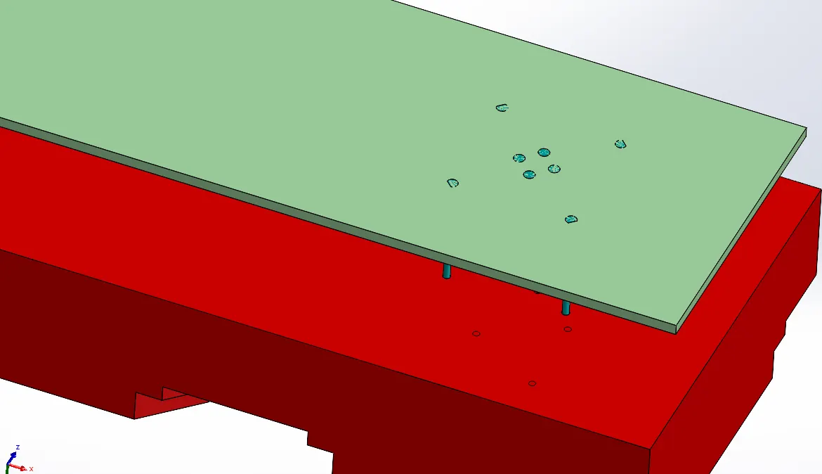
- Relief holes
- 3mm deep (same as pins head thickness).
- 12mm Dia
- Contact at plane part of head (No Relief).
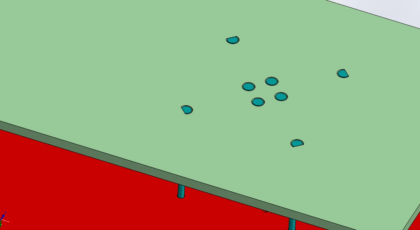
- Through holes
- 6.95mm dia
- Pins dia 0f 6mm
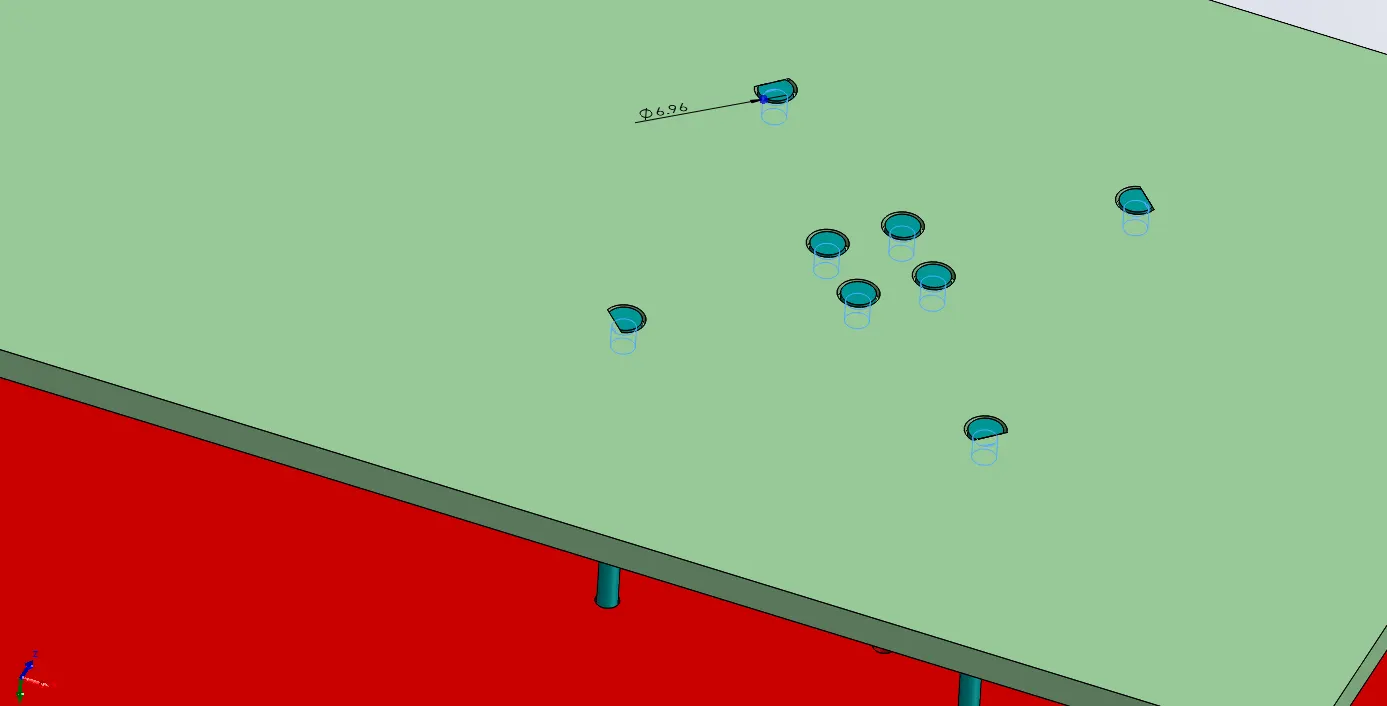
- Retainer plate
- 5mm thickness
- same size as ejector plate.
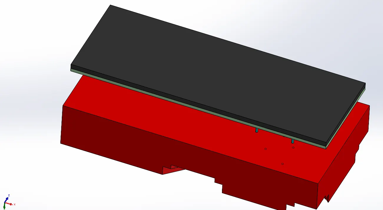
In Cavity Steel,
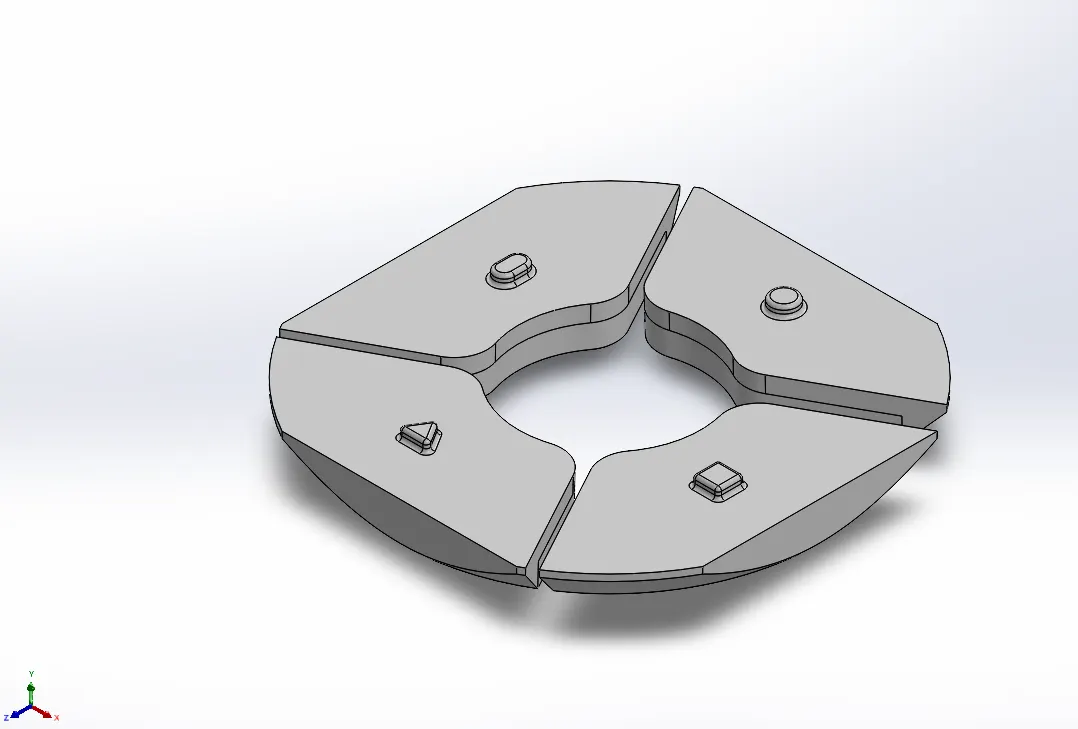
- Four Inserts of four slider cavity.
- 4mm deeper w.r.t. cavity surface
- Blue colored
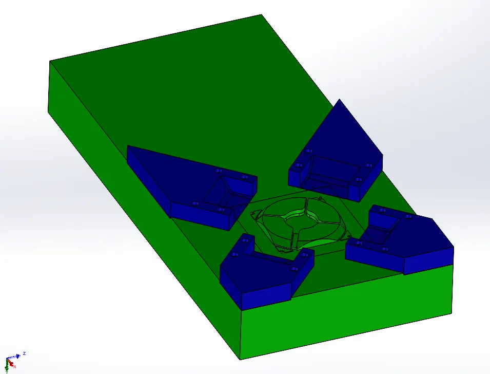
- Different shaped feature on each Insert of 5mm Deep.
For aiding in positioning of each Insert relative to Cavity steel as well as each other.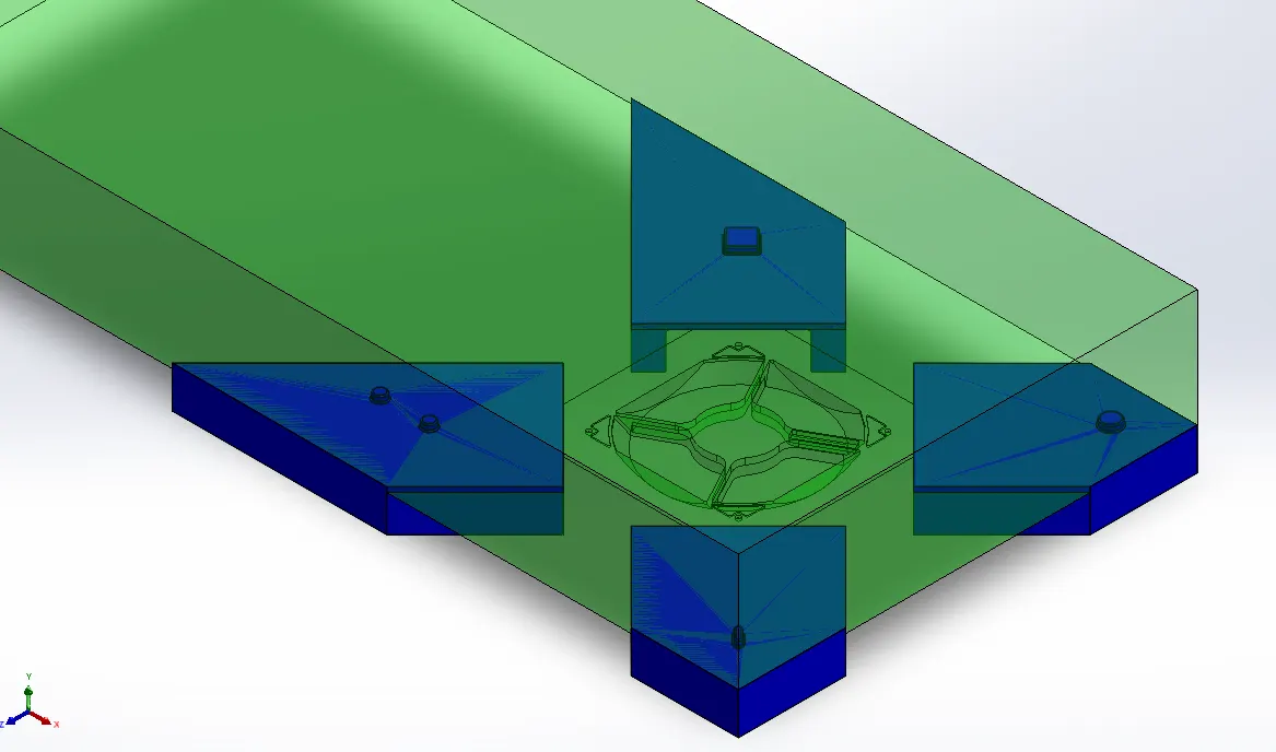
- Matching features formed on Cavity Steel.
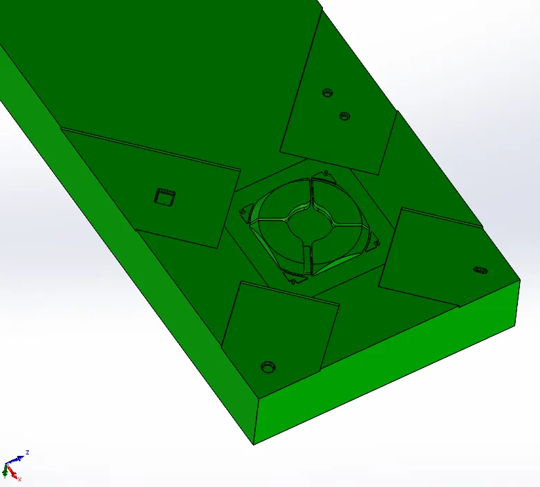
- M6 clearance hole (through) for fixing Inserts.
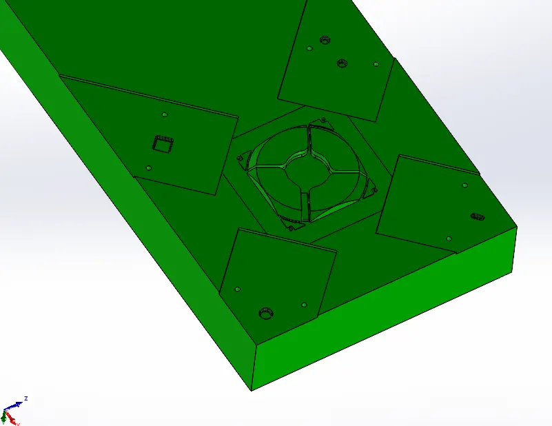
- Two M6 tap holes (blind) on each Insert.
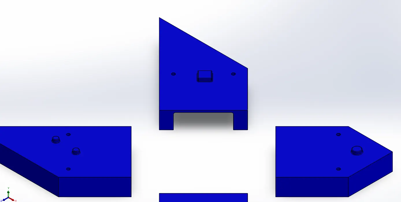
- Fillets for ease of machining on Cavity steel.
- Matching fillets on Inserts.
- Four Inserts (in white) for ease of machining Cavity steel.
- Features for eliminating positioning errors.
- Matching Features on Cavity steel
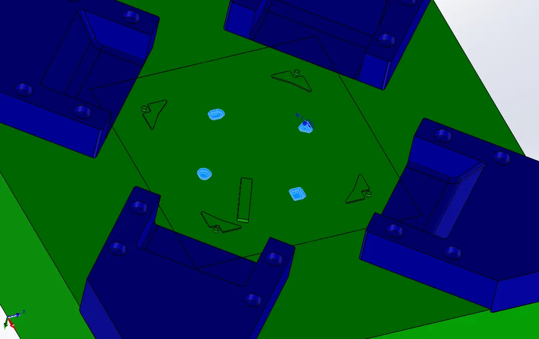
- Fixed by M6 bolts.
M6 clearance holes on Cavity.
M6 tap holes on Inserts.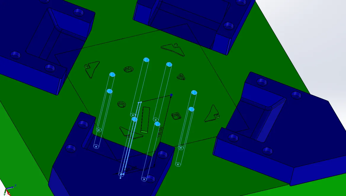
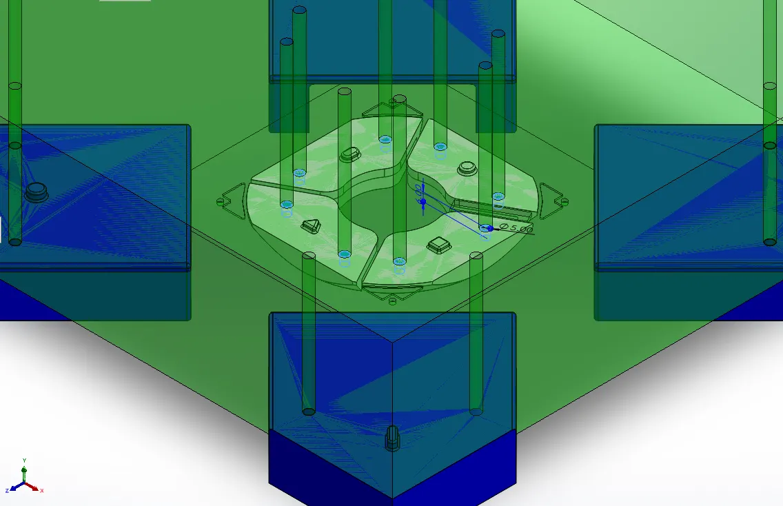
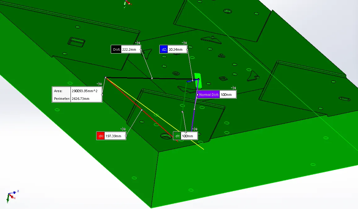
- Cavity steel Pre-Machined thickness adjusted to nominal value.
Normal Dist: 103.02mm >> 100mm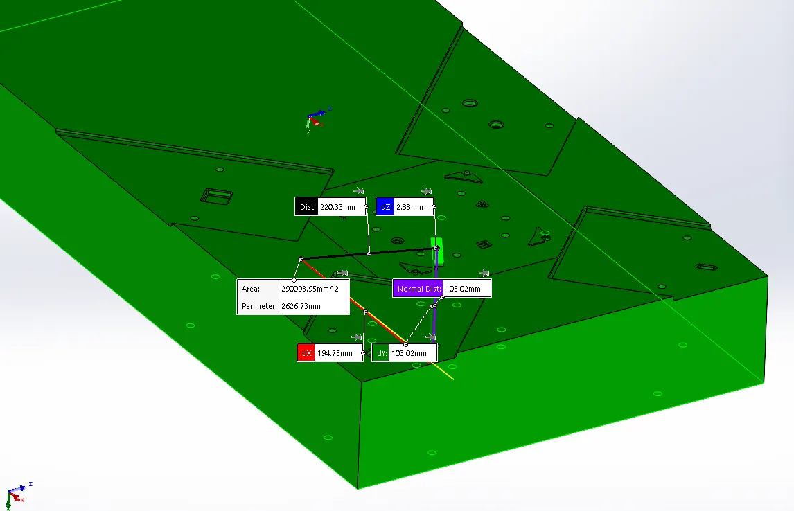
SPRUE, RUNNER and GATE SYSTEM:
In Cavity Steel,
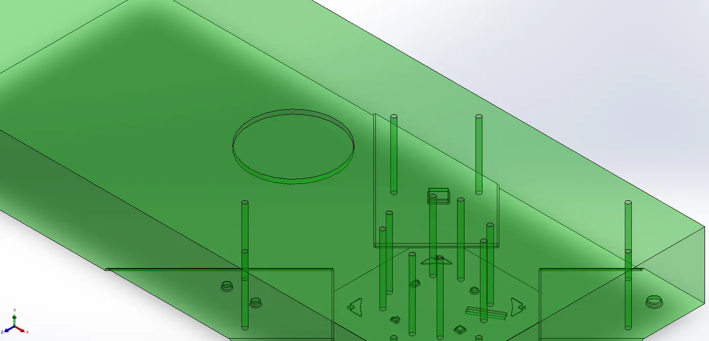
- Sprue:
Nozzle alignment cut.
120mm Dia
6mm Deep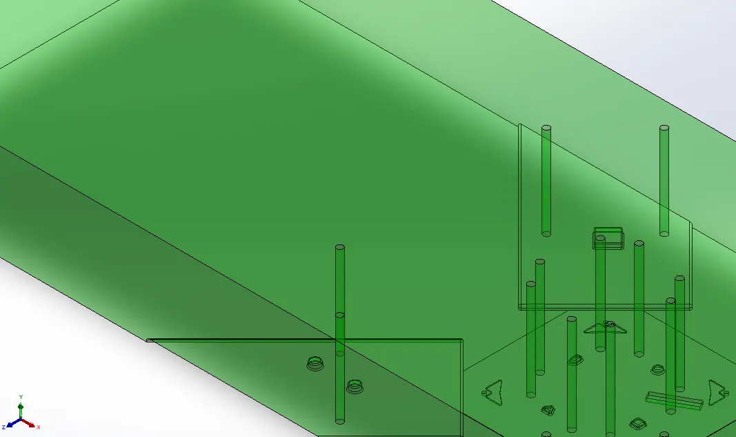
- Start Dia 5mm
3.5 Tapered though EXTRUDED CUT.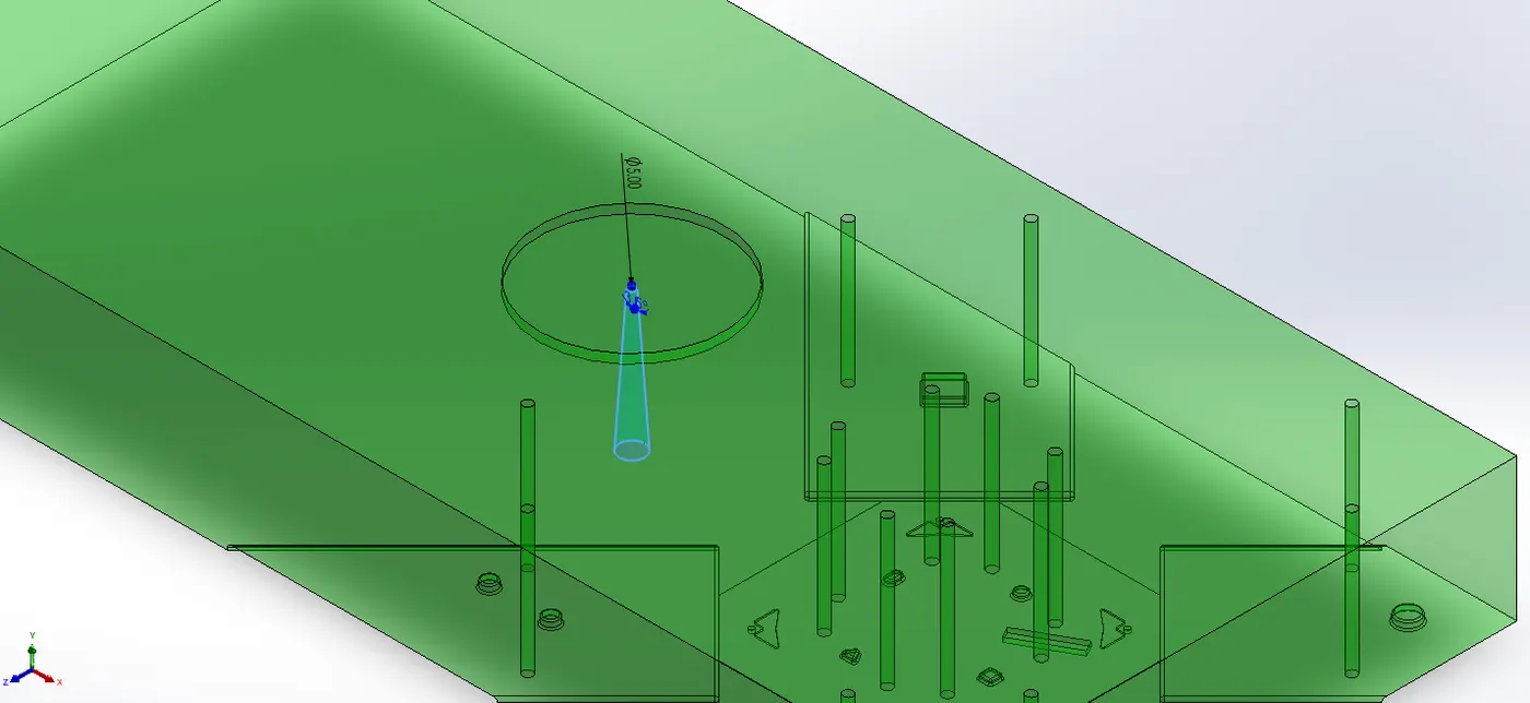
In Core Steel,
- Identical end dia hole (as cavity steel) of 5mm deep.
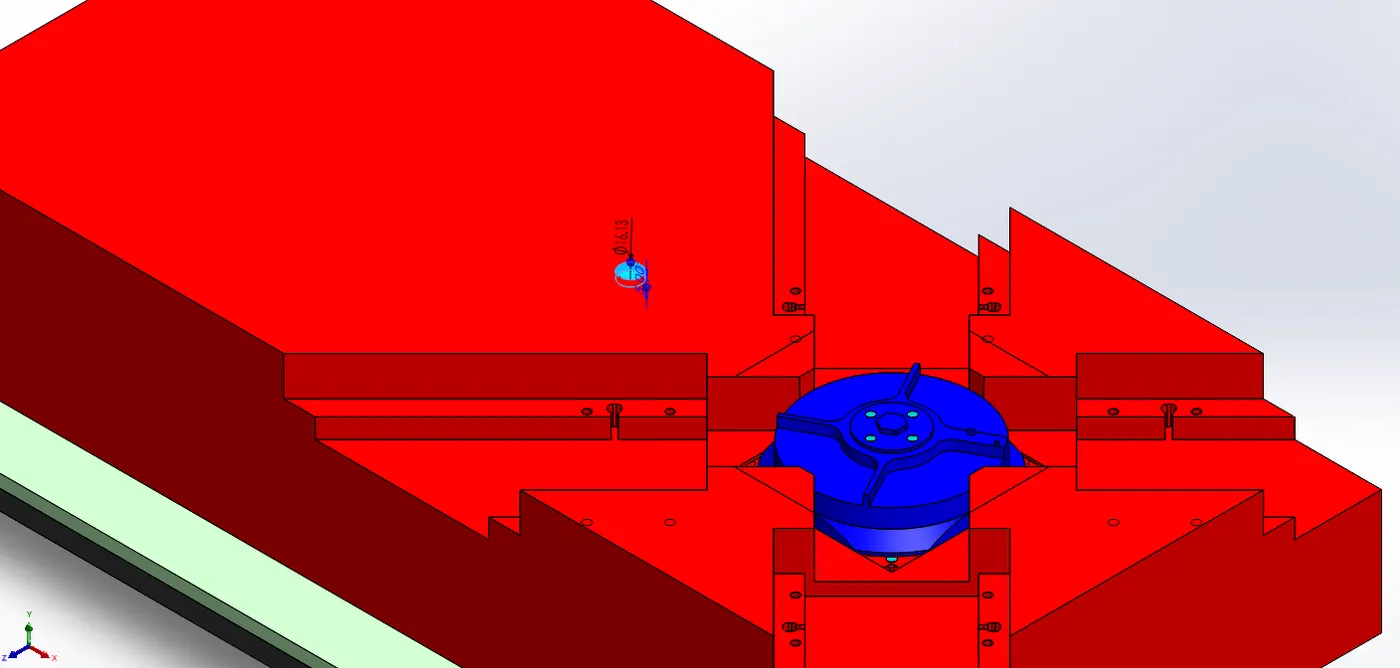
- Runner Body
4mm deep
9.5mm width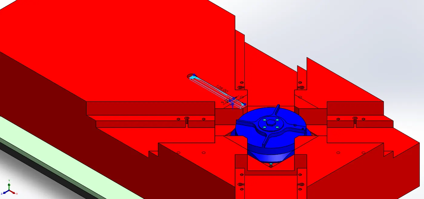
- Gate body
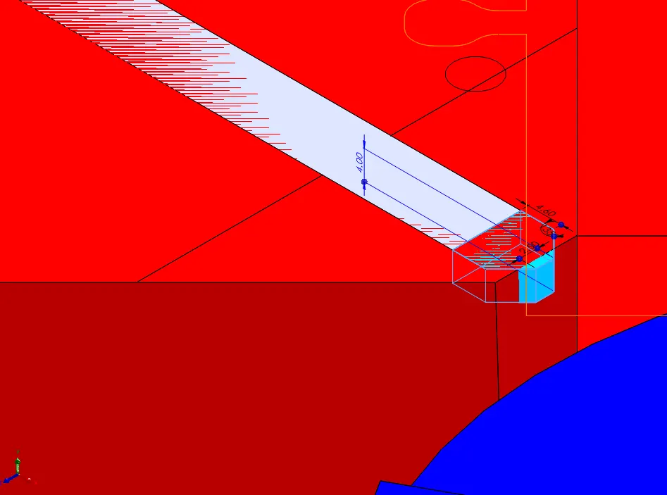
- 40deg Draft on Gate body.
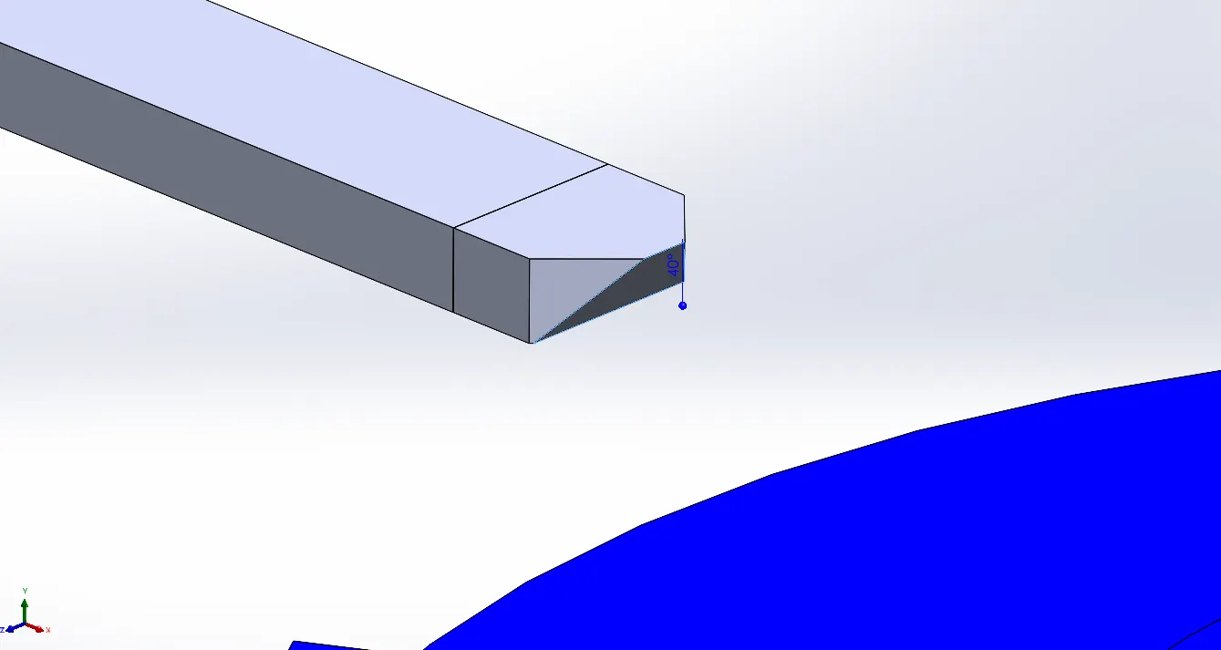
- Runner and Gate combined.
Appropriate fillets added.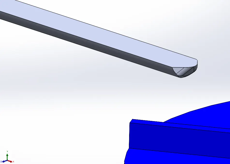
- Material added for proper removal.
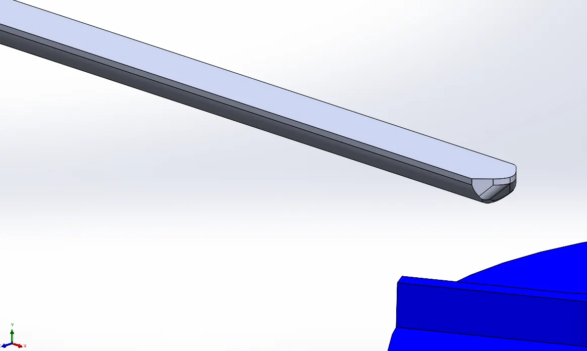
- Body subtracted from Cavity Steel.
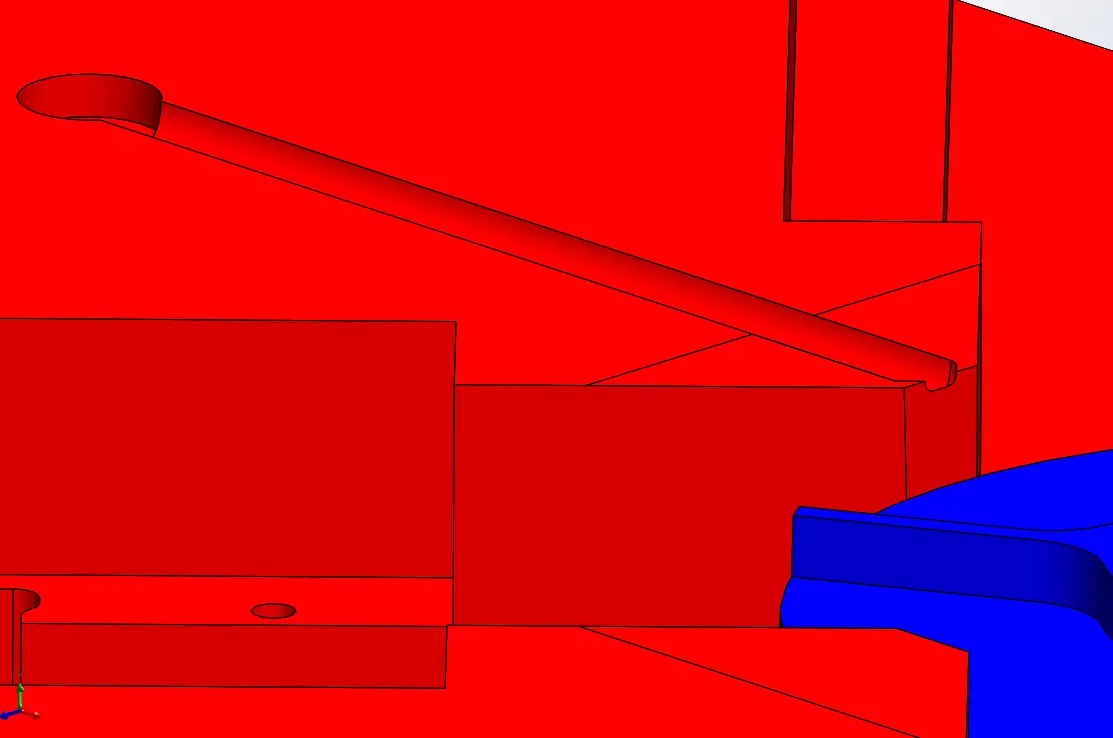
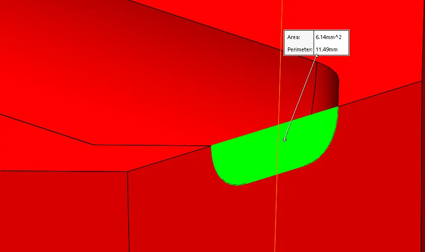
- Gate Area = 6.14mm^2
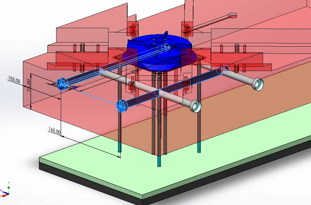
COOLING CHANNELS:
Inlet and Outlet channels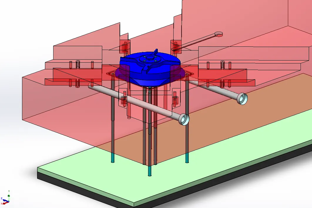
Circulating channels added.
Openings will be closed for circulation in series.
AIR VENTS:
- 1mm thick body is created.
Air to be passed thorugh relief gap between Core and Cavity.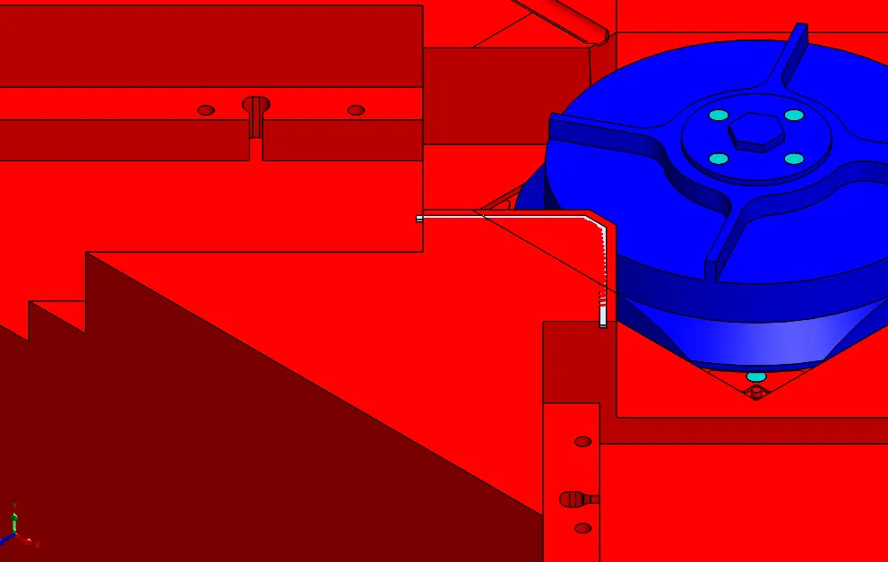
- 0.3mm deep gap for air to pass from Mold part to Air venting channel.
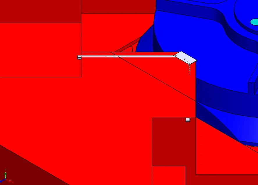
- Both bodies are combined.
Fillets are added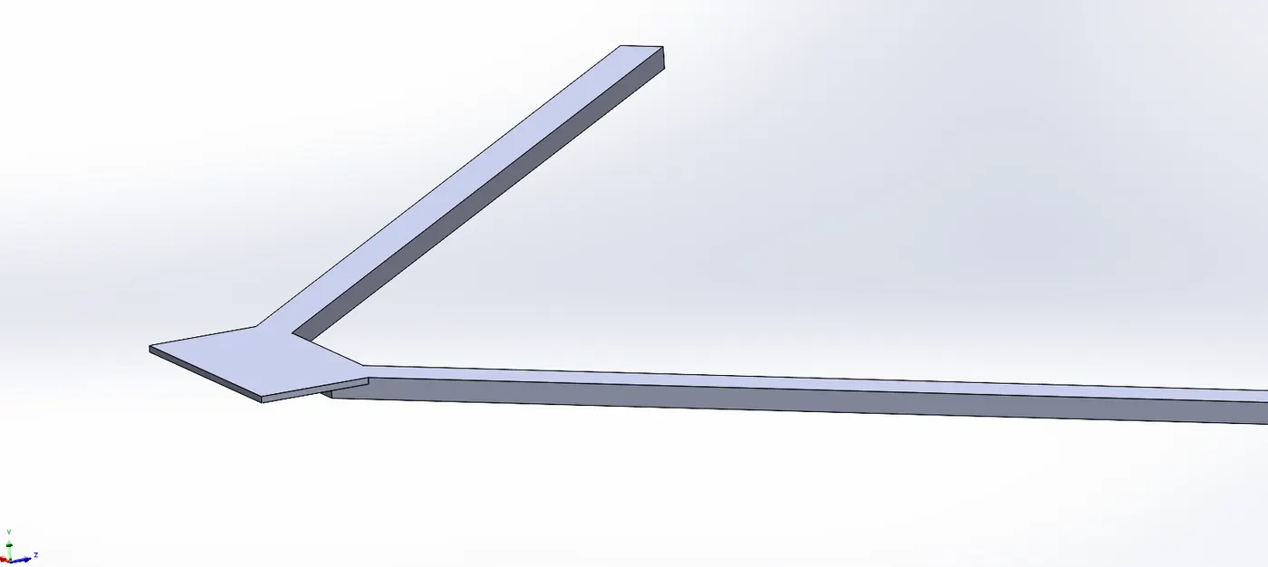
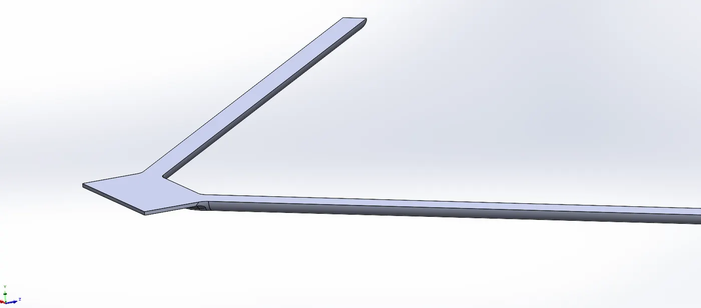
- Material added on top for proper subtraction from Core
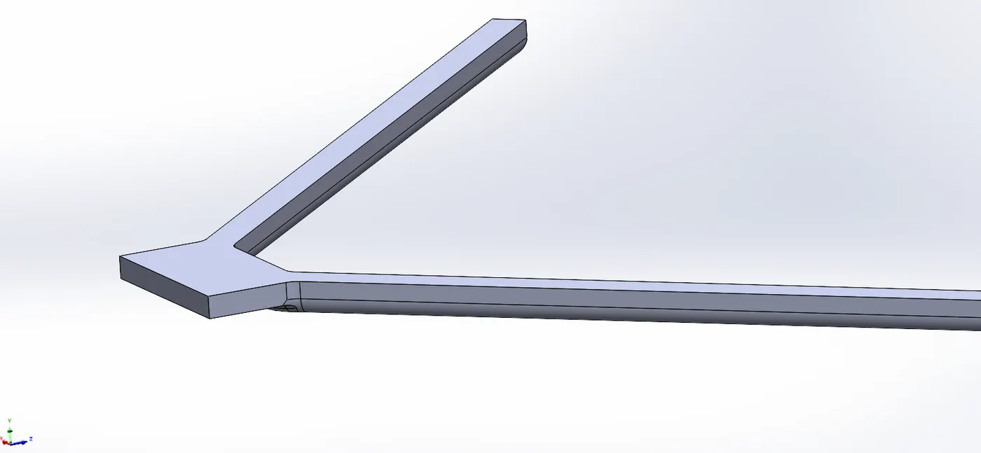
- Body is patterned
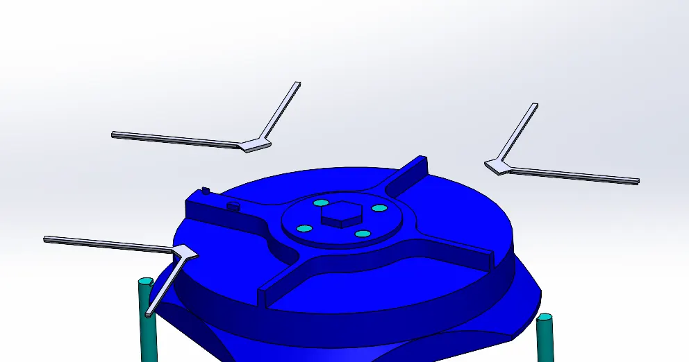
- Channel formed by Subtraction (Magenta colored)