Week 8 - Challenge 2 - Switch Bezel Design
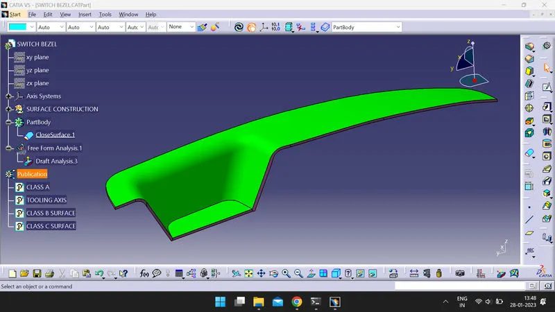
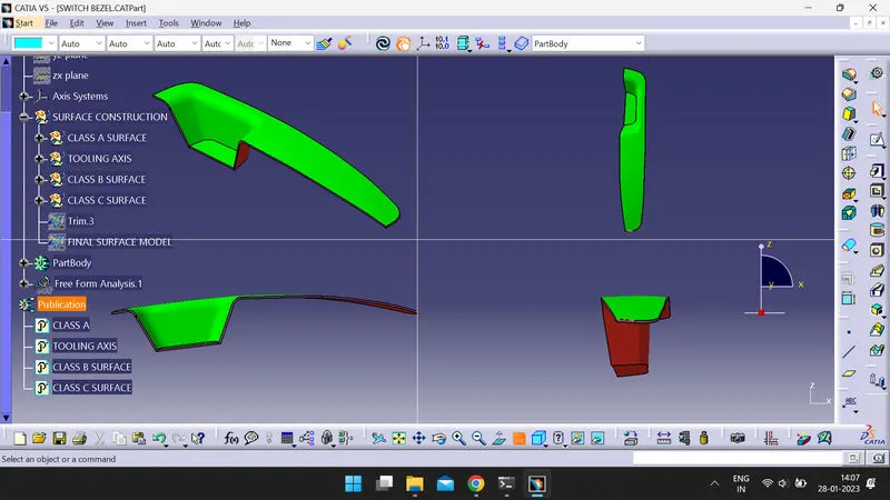
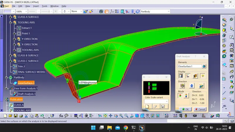
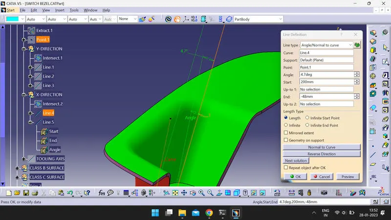
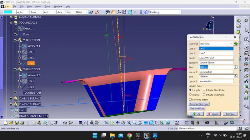
As shown above, the draft angle of 3deg (approx) on shown surface was achieved through adjusting angle of Line5 in Tree structure from 3deg (standard nominal draft angle) to 4.7deg as shown below.
Change from 3deg to 4.7deg while creating tooling axis was because for 3deg in draft analysis the surface shown above was having draft value of less than 3deg hence it would have effected that surface while mold removal.
TOOLING AXIS CREATION METHOD:
INPUT: CLASS A SURFACE
STEP 1. How to find direction of tooling axis(i.e. x,y or z): We opt for the direction from which no feature of required product get compromised while mold opening process. And we avoid side core feature as it increases tooling cost until unless no other option is available.
Hence, we choose the direction which will eliminate need of side core and at same will not deform the product produced.
STEP 2. Deciding from which surface and point be tooling axis passing from: Plane normal to the direction of tooling axis is chosen.
If there is any hole on surface then we choose the centre of circle as point otherwise we just choose the centroid of any surface parallel to the plane chosen.
Example shown below.
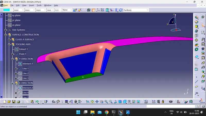
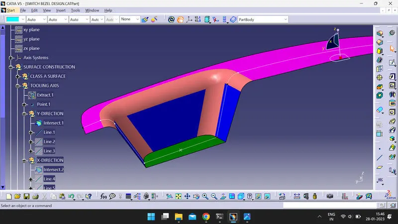
STEP 3. Creating Bisecting Line in other two directions: Bisecting line is created in one direction (any other than tooling axis direction) by using INTERSECT command which will give a line passing through tooling axis point in that particular direction.
For that view, either one surface or two surface (depending on the class A surface given) closest ones (in terms of draft angle) to the tooling axis is chosen and a parallel and coinciding line is created on each surface.
In case of two surfaces, Bisecting line is created. In case of single surface, a line created at an nominal draft angle of 3deg (subject to change if needed) passing through the point created for tooling axis.
Step 3 is repeated for other remaining direction.
As shown below.
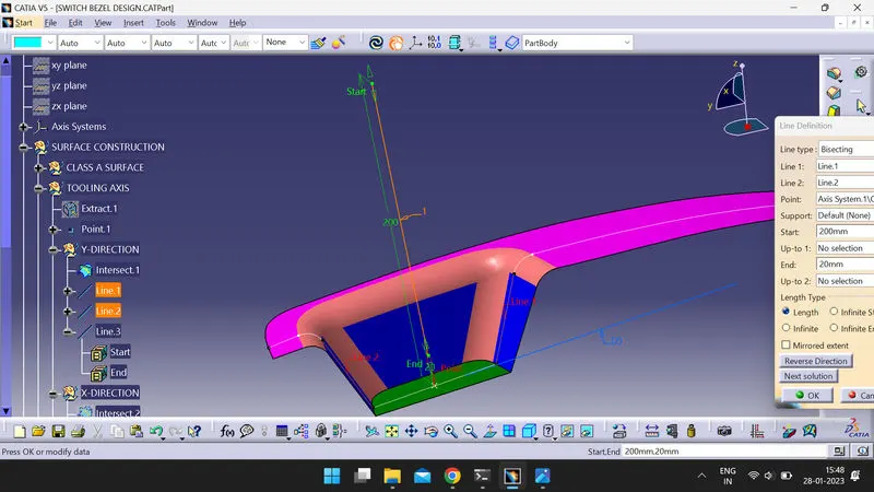
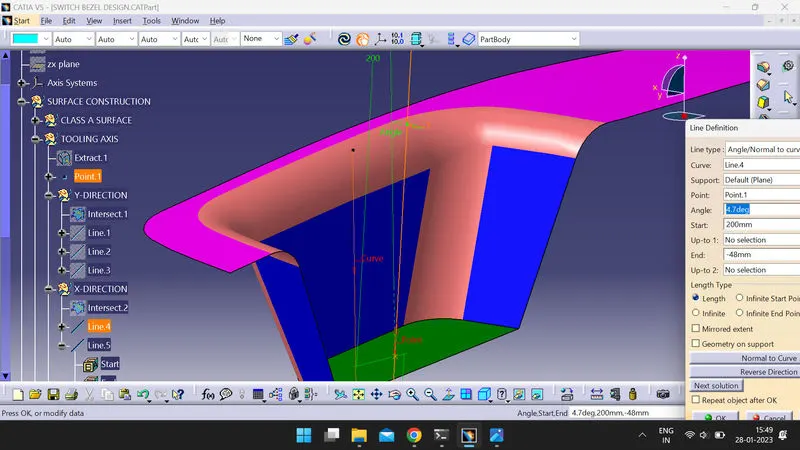
STEP 4. Creating Tooling Axis: Two intersecting lines obtained is then bisected to form TOOLING AXIS which will help in given draft for CLASS C Surface as well as in Draft Analysis. As shown below.
DRAFT ANALYSIS:
INPUT: CLASS A SURFACE or SOLID BODY, DRAFT TOOLING AXIS.
Draft Analysis is done on surface or body to check the ejectability of the component from the mold without compromising the surface form as well as finish.
Generally,
GREEN color symbolizes that a surface is passing the draft angle limit setted (usually 3deg).
RED color symbolizes that surface has negative draft angle.
CYAN color symbolize the draft angle on surface being positive but below the draft angle limit.