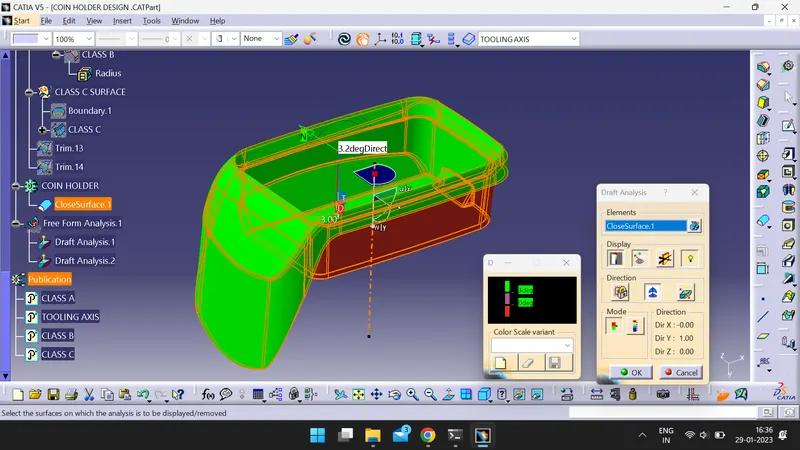
Week 8 - Challenge 3 - Coin Holder Design
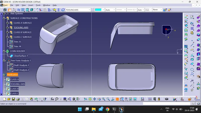
TOOLING AXIS CREATION:
INPUT: CLASS A SURFACE
BISECTING METHOD:
1. Extracting BIN FLOOR surface, then taking point in centroid for defining tooling axis origin and assigning axis system at that point.
2. Intersect 1 is formed in Z-direction and closest surface (in terms of least draft angle) to the Y-direction is taken on each side surface and lines is formed on both sides. A bisecting line is formed from those two line passing through the point defined in Step1.
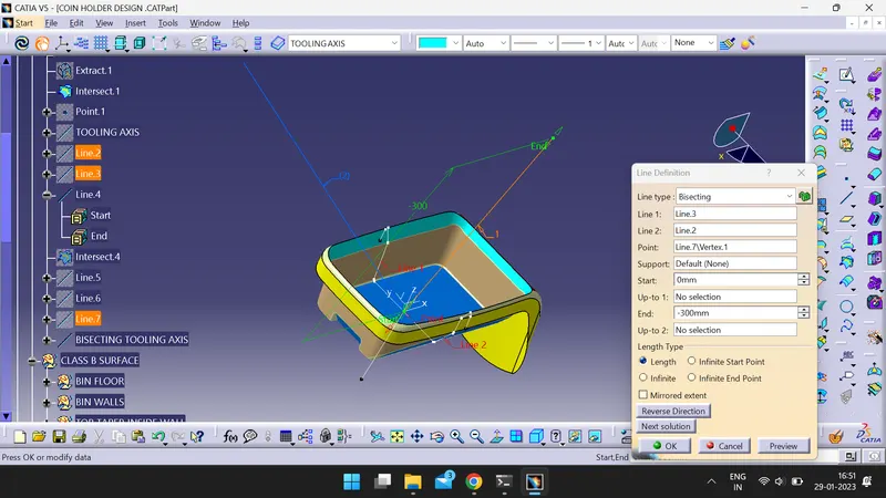
3. Step2 repeated in X-direction.
4. A bisecting line is formed from line obtained from Z and X direction.
5. Line formed is mentioned in Tree under TOOLING AXIS geometrical set by the name of BISECTING TOOLING AXIS.
After running Draft Analysis, The bisecting tooling axis is not feasible as mold removal direction.
Therefore, Since the ClassA surface have bin walls close to 90deg to the bin floor, the ClassA surface obtained may have been designed using a line normal to the bin floor surface.
By running draft analysis and taking tooling axis as line perpendicular to bin floor horizontal surface which is passing through its centroid, the above statement is confirmed and TOOLING AXIS is created.
DRAFT ANALYSIS:
1. Input: CLASS A SURFACE and TOOLING AXIS
As shown in figure below the steepest surface is clearing nominal draft value (3deg) by 0.2deg.
GREEN color shows when surface draft value is greater than 3deg.
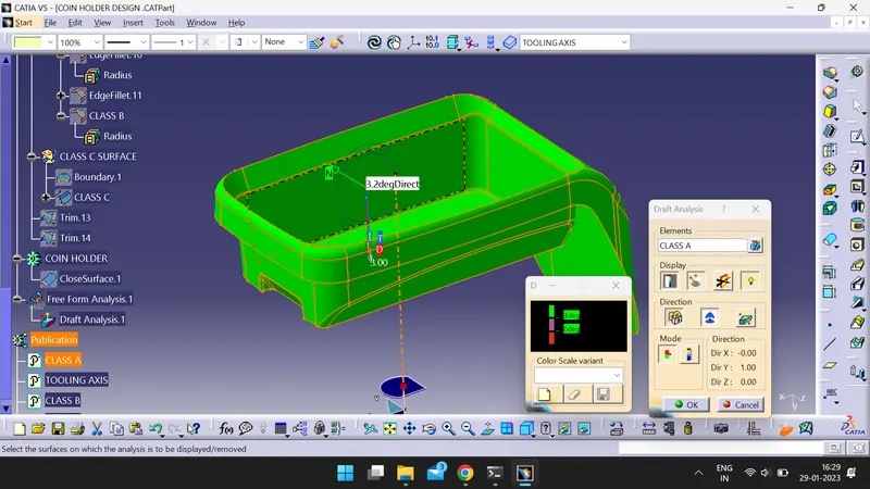
2. Input: SOLID BODY and TOOLING AXIS
The draft analysis for solid body is shown.
GREEN color on CLASS A SURFACE shows draft angle being greater than 3deg hence mold removal without any deformation to the surface of component can be achieved in direction of tooling axis. (i.e. in negative Y direction).
RED color on CLASS B SURFACE shows negatice draft angle throughout that surface. Therefore, mold removal without any deformation cannot be achieved in negative Y direction.