Project 2
AIM:
To route wiring harness bundle for the given car body.
OBJECTIVE:
- To create the wiring harness routing for the given Car body using necessary connectors, clips and clamps.
- To create flatten view drawing file.
- To apply the protection covering.
- To apply the industry best packaging rules and best practices studied in this course.
PACKAGING RULES:
- Avoid routing through small structural holes and opening. This avoids chaffing and handling of wiring harness during installation.
- Avoid harness routing and clipping in blind zone of operator which helps in easy acces during service and assembly.
- Provide additional slack to the harness corresponding to the surroundings and bending requirements. This ensures the routing meets the clearance to the surrounding parts.
- Avoid routing over bolts. It may damage the harness.
- Avoid routing near sharp edges, if not possible provide rubber beading for sharp edges.
- Minimum branch breakouts should be 50mm.
- Distance between two clamps on staright branch should be maximum of 200mm.
- Keep harness away from transmission, dynamic assemblies like propeller shaft.
- Usage of Guiding channel if required.
- Limit the no. of branches coming out from single branch to 4nos.
INPUT DATA:
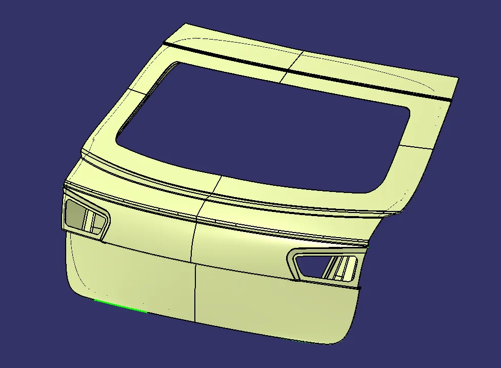
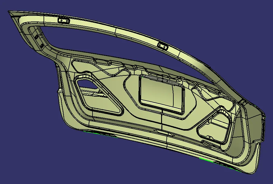
CONNECTORS AND CLIPS USED:
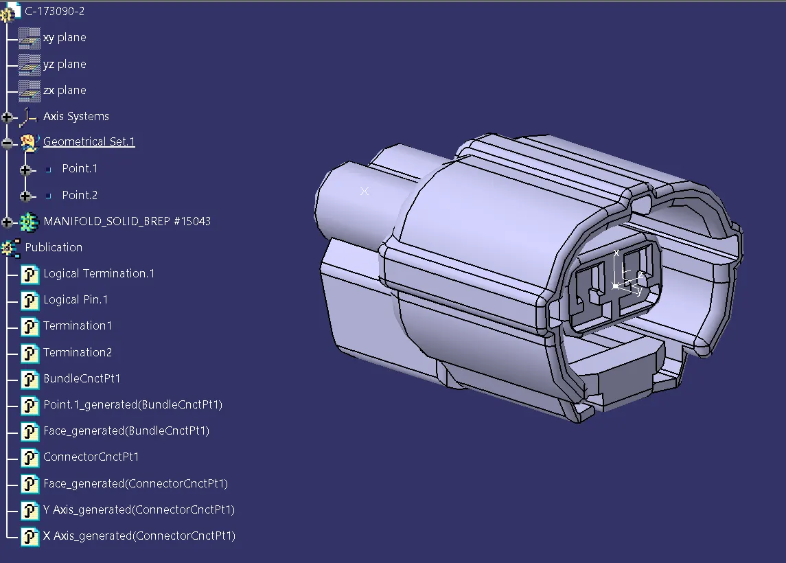
1. C-173090-2
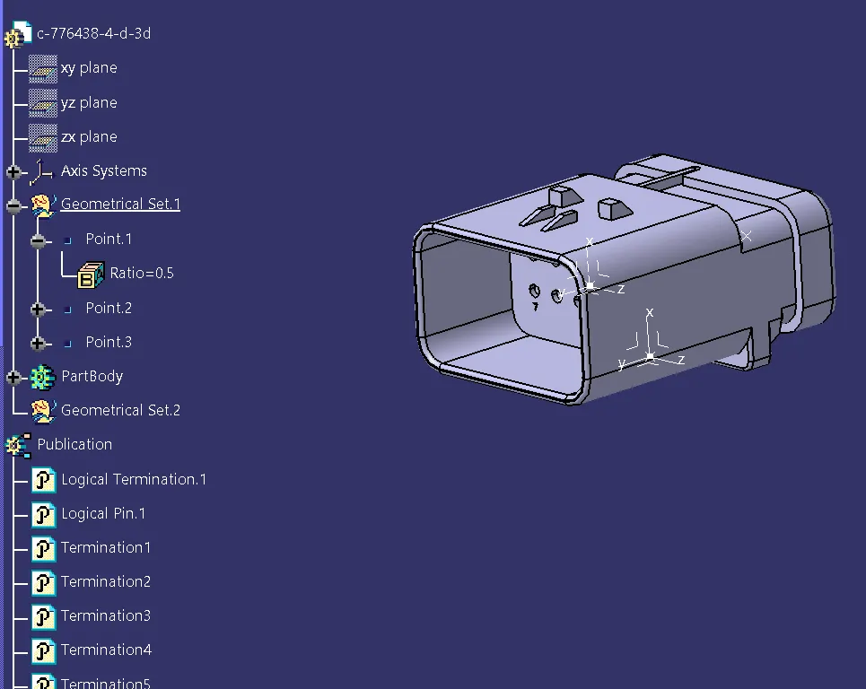
2. c-776438-4-d-3d
3. C-1563689-1
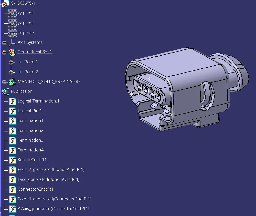
4. C-1924487-2
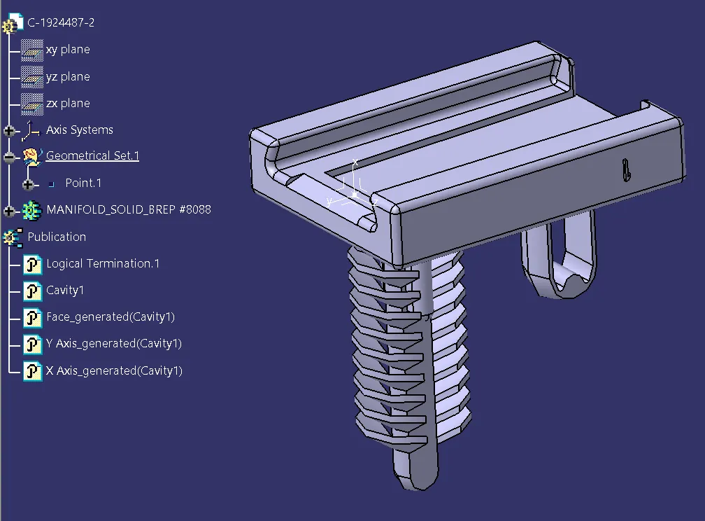
5. L-CLIP
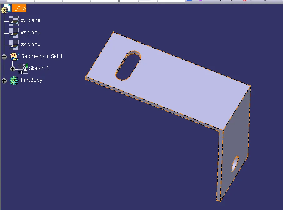
6. FIR TREE CLIP 5MM
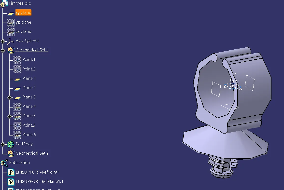
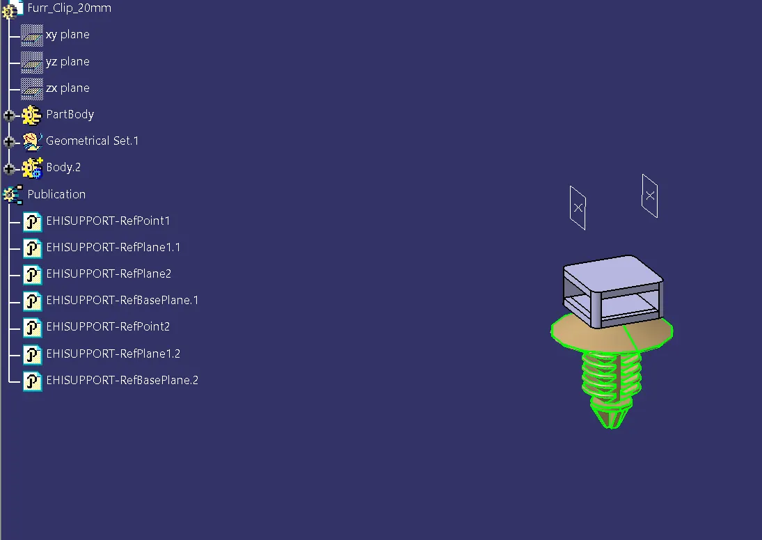
7. FIR TREE CLIP 20MM
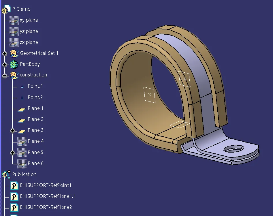
8. P-CLAMP
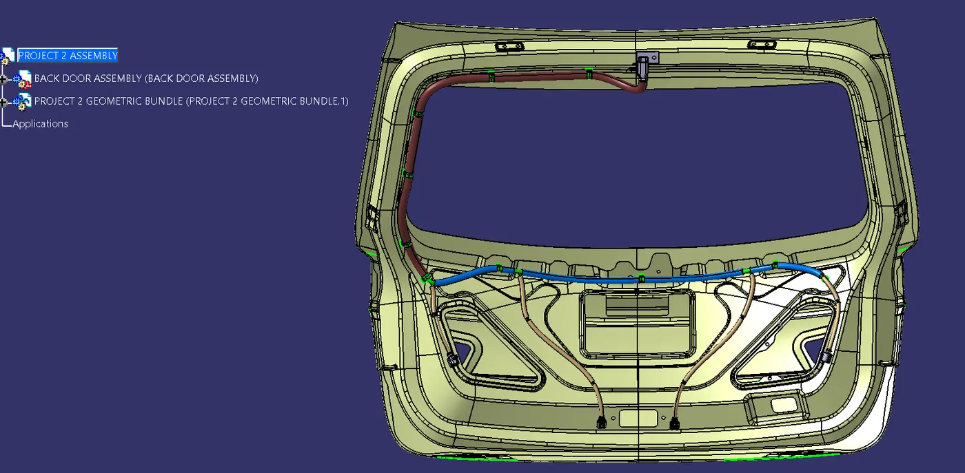
ASSEMBLY TREE STRUCTURE:
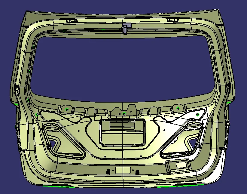
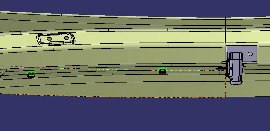
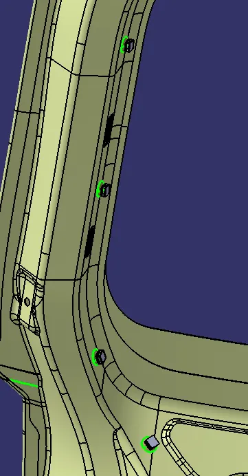
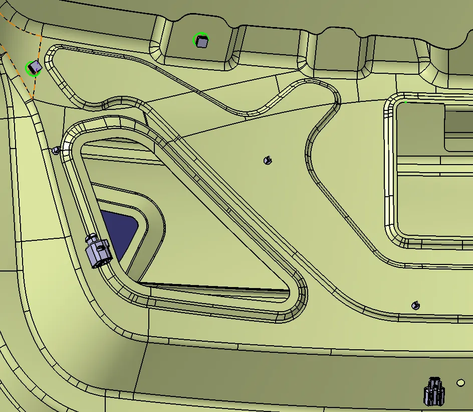
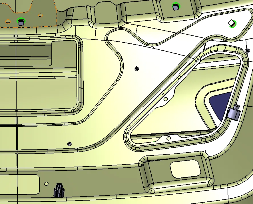
CLIPS AND CLAMPS ALIGNED IN BACK DOOR:
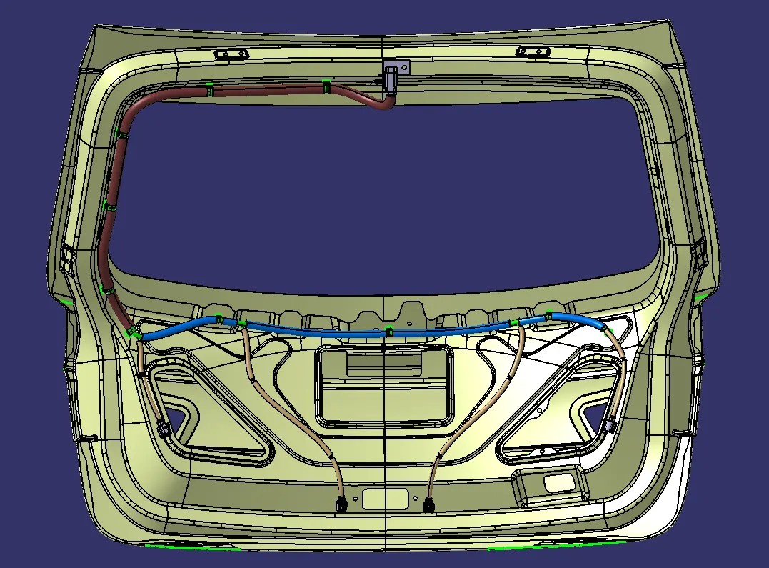
WIRING HARNESS ROUTED IMAGES:
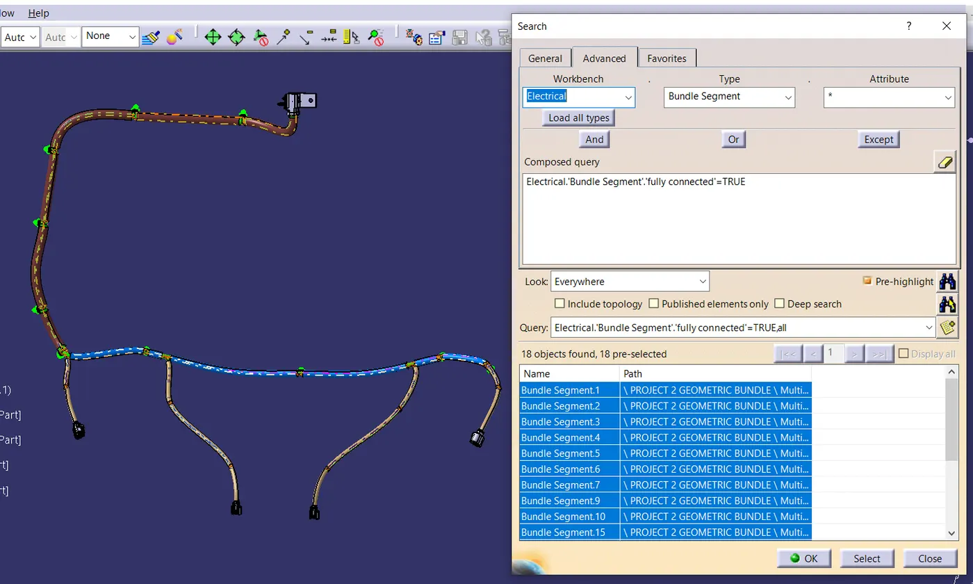
BUNDLE CONTINUITY CHECK:
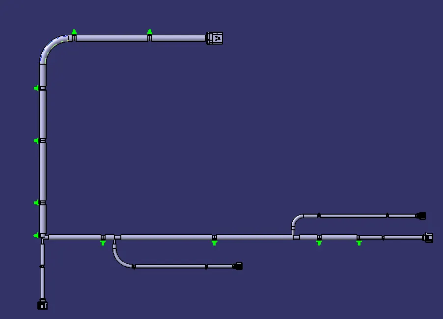
WIRING HARNESS FLATTENED FILE:
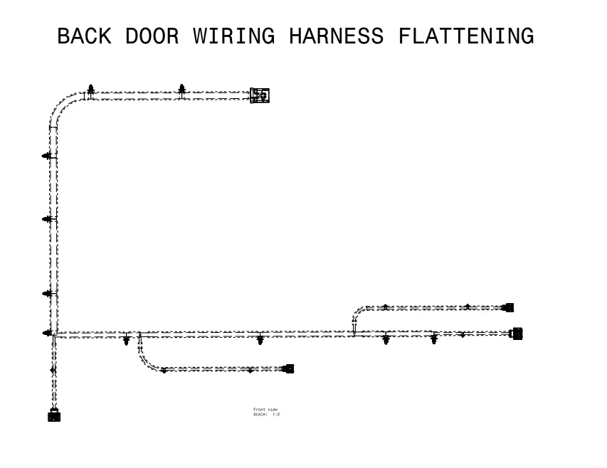
DRAWING:
OVERVIEW OF STEPS FOLLOWED IN THE ABOVE DONE ASSEMBLY:
STEP 1: Create a product file where the part and product file will be assembled.
STEP 2: Create another product file as Geometric Bundle where connector and final routing is saved.
STEP 3: Add the Engine , Geometic bundle in a single Product file.
STEP 4: All the connectors, clips, clamps and channel part are to be electrically defined and added to the catalogue.
Step-5:
Adding all the required file to the Geometric bundle and positioning them using "SMART MOVE" and " MANIPULATION TOOL"
PACKAGING RULES CONSIDERED DURING WIRING HARNESS ROUTING:
- P-clamp, fir tree clips and cavity are added to the Geometric bundle as they are electrically defined and are part of wiring harness routing and should be provided with the wire bundle package.
- Minimum bundle length of 50mm to be maintained.
- Slack should be provided enough so the wiring harness doesnt get damaged due to engine rocking or idle conditions.
- Wiring harness should be done by considering easy manufacturing and serviceability.
- Additional slack can be provided depending upon the surrounding and bending requirements.
- avoid excess slack by minimising the slack or by giving zero slack wherever possible.
- Every connector should be given with a slack so that there will be no tension on wire bundle.
STEP 7:
Once routing is finished. check for routing connectivity
STEP 8:
WIRING HARNESS FLATTENING:
To create the wire harness flattening we need to create another product file and navigate to Electrical Harness Flattening workbench.
In the workbench define the Harness Flattenig parameters anad extract the geometrical bundle from the wiring harness product file.
Select the branches and flattend the entire geometrical bundle.
The bundle can be rotated and rolled with a proper radius in or to fit the drawing sheet.
STEP 9:
After the Harness if flattened in the respective product file and workbench is flattened and represented in drawing sheet..
CONCLUSION:
Thus the objectives of the project are achieved. Required images are provided. Zipped folder of the files are attached.