Project 2
AIM:
To route the wiring harness on given car body of back door and prepare flatten view drawing in CATIA V5. Application of all packaging rules, industry best practices studied in this course shall be demonstrated in design. Apply protection coverings as required.
OBJECTIVES:
- Selection of connectors and support equipments
- Packaging rules and industry best practices
- Define connectors and clips/clamps as an electrical component
- Placing connectors and clips/clamps for required position
- Creating wiring harness context assembly
- Harness installation
- Check harness continuity
- Wiring harness flattening
- Flatten view drawing
Selection of connectors and support equipments:
- Evaluate the given back door cad data and select the required connector per desired working specification.
- In first we need to check how many connectors are needed and consider the harness installation ways and select the clip and clamps.
- For the back door we can easily route the wire harness because it is free from water and dust.
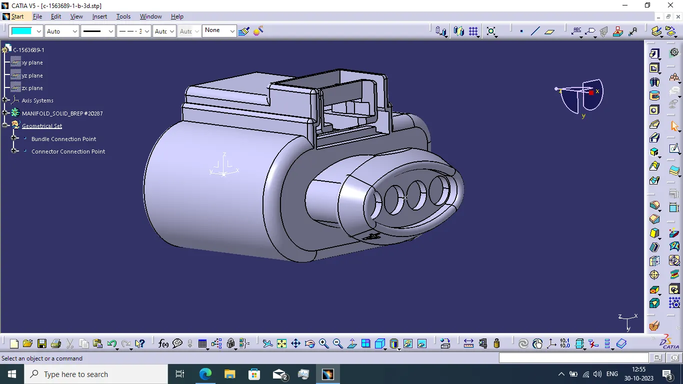
- As per the given back door of car body we want 2 connector for tail light, 1 interconnection connector for connect back door wiring harness to the main harness, 1 connector for wiper motor and 1 connector for number plate light.
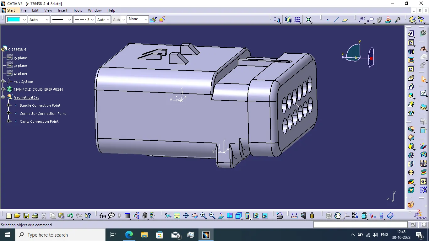
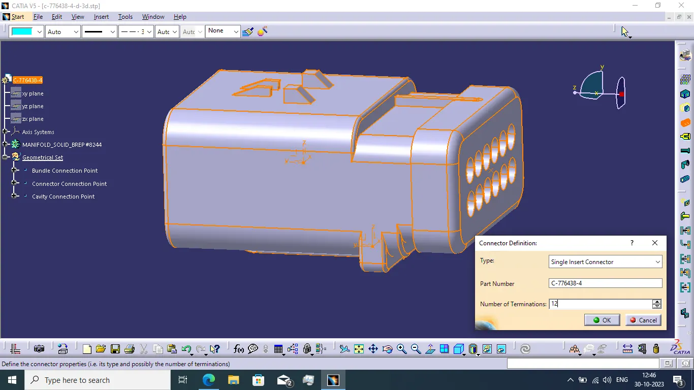
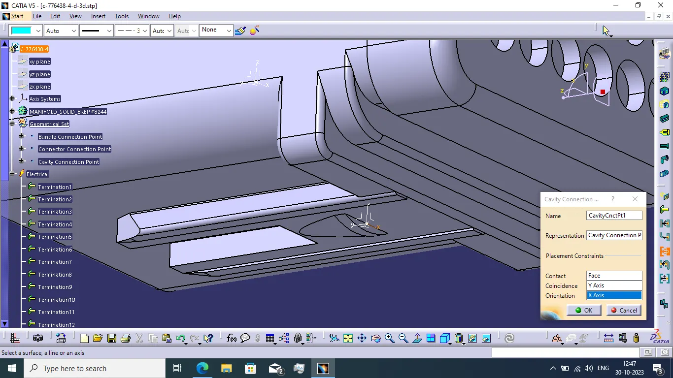
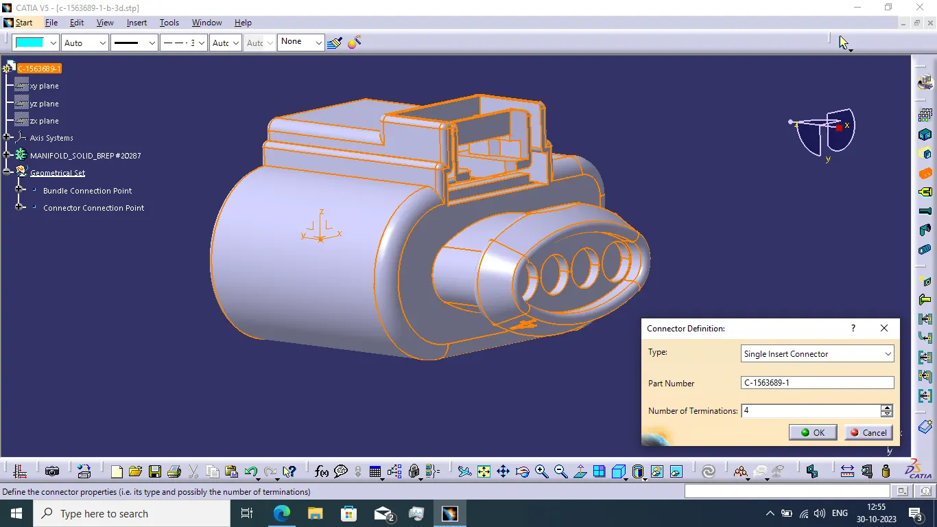
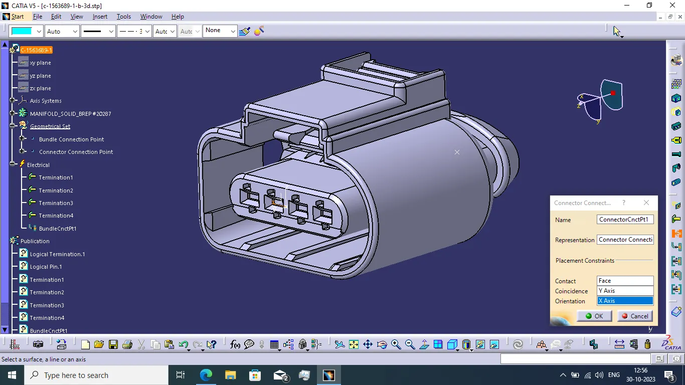
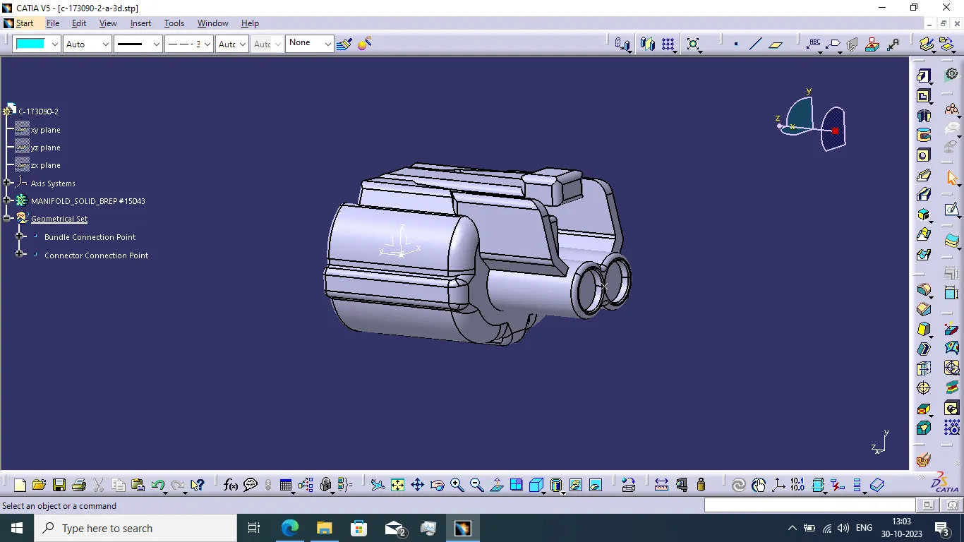
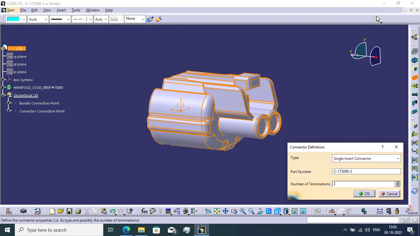
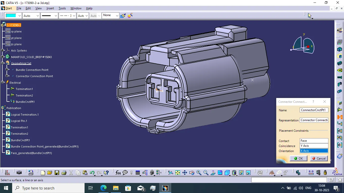
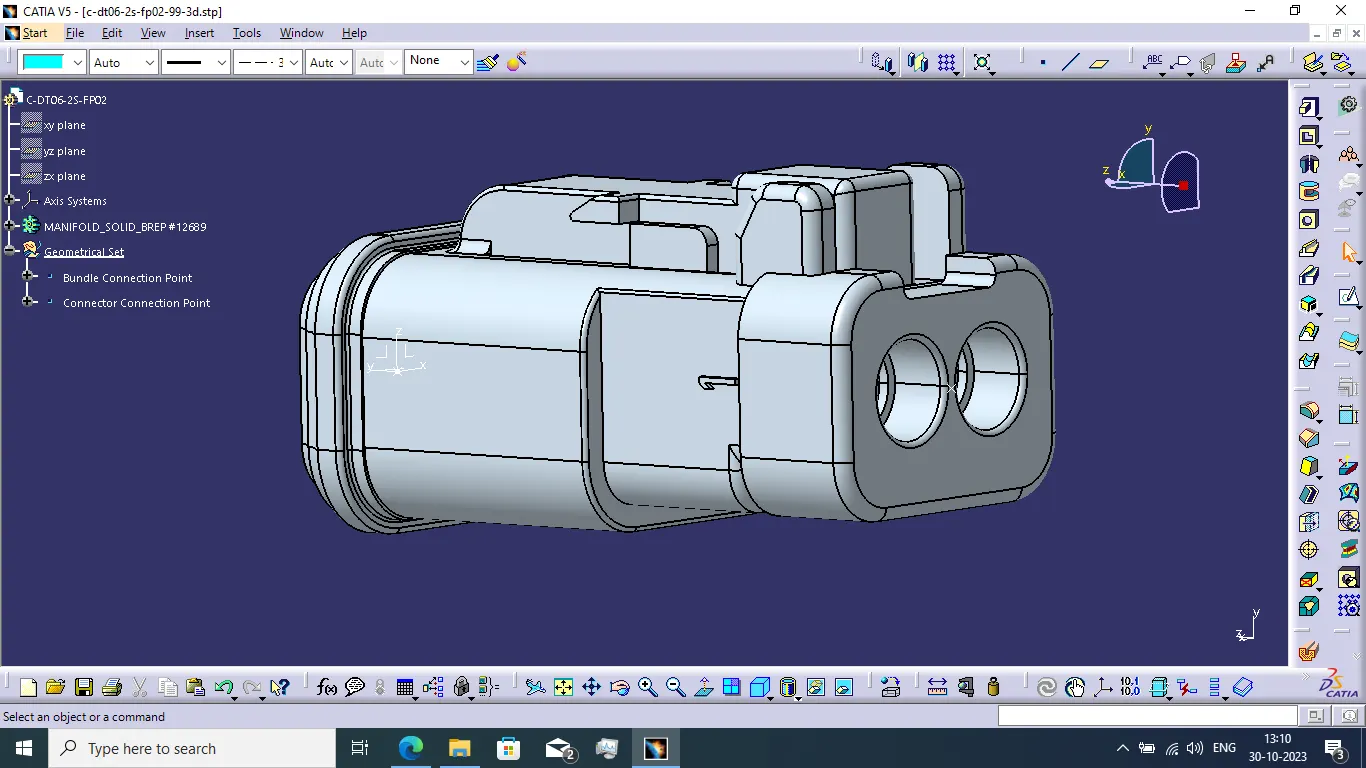
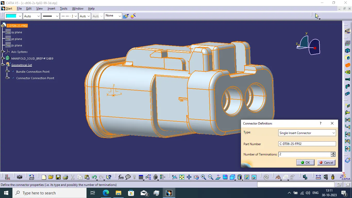
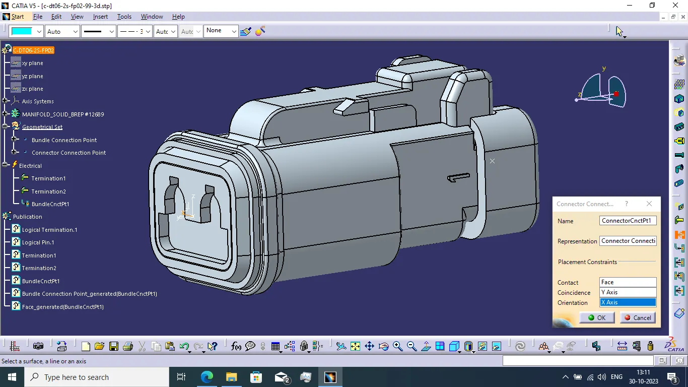
- I have selected 4 different connector as per the required specified connectors. We use 12 pole c-776438-4-d connector as interconnection connector, 4 pole connector c-1563689-1-b as tail light connector, 2 pole connector c-173090-2-a as wiper motor connector and 2 pole connector DT06-2S-FP02 as number plate connector.
- I used furr tree clip as a supporting equipement is used to guide the harness.
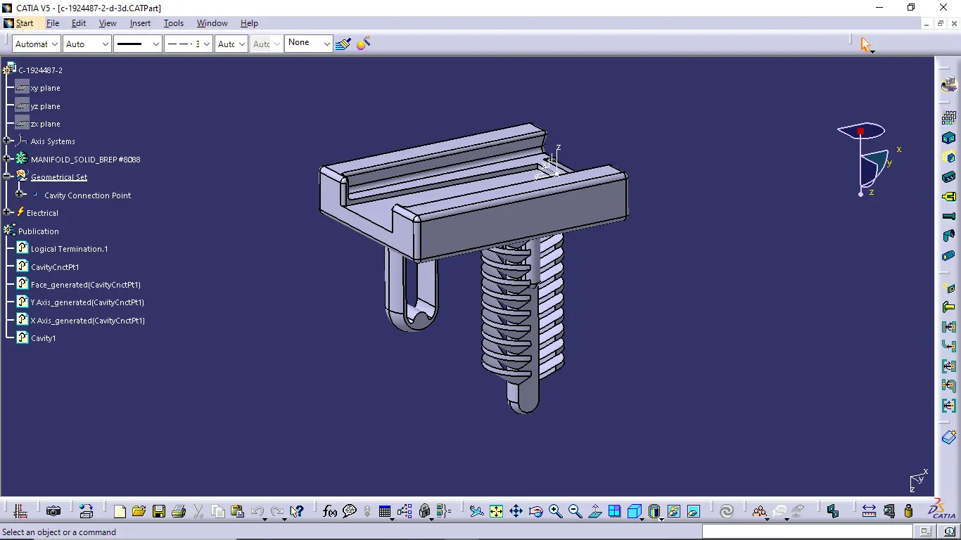
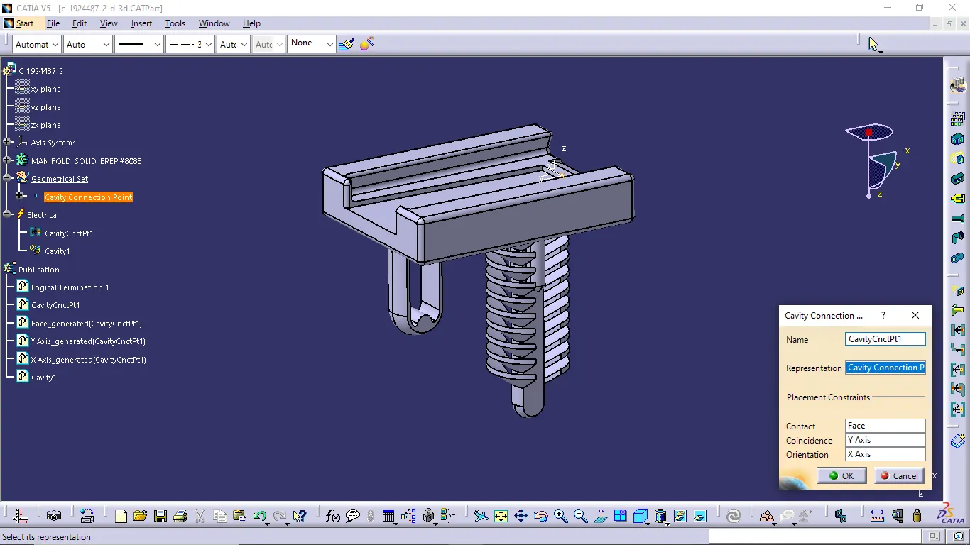
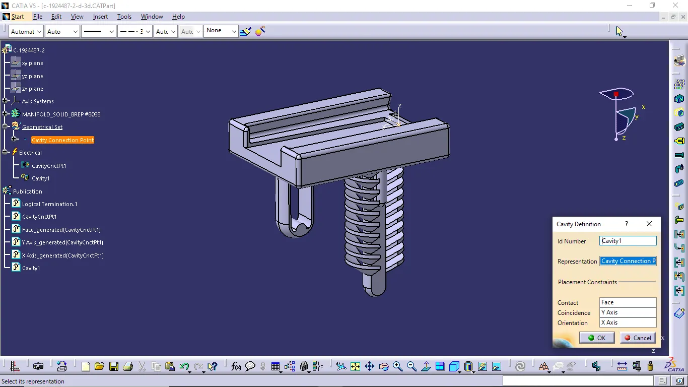
- We want to give the support for interconnection connector for avoid vibrations and movement of the connector. So i use c-1924487-2-d as a cavity part.
DESIGN CRITERIA FOR WIRING HARNESS:
- Wiring harness should be routed in such a way that it is easy to assembly and easy to access in case of service or failure analysis.
- Wiring harness should be secured properly so that it will not get damaged by surrounding component interaction.
- Wiring harness should be kept away from sharp environment like sheet metal bracket edges, corners, panel edges and etc.
- Dynamic conditions of vehicle components should not damage wiring harness. ensure that enough slack is provided to avoid the damage.
- Keep harness away from the components which are subjected to movements during their normal operation like door hinges and door latch.
- Ensure that harness is not visible or exposed in vehicle.
PACKAGING RULES AND INDUSTRY BEST PRACTICES:
- Wiring harness routing shall provide ease in manufacturing, accessibility, easy removal and easy maintenance of attached equipment and wiring harness.
- Avoid the harness routing and clipping in blind zone of operator during harness assembly or service.
- Provide additional slack to the harness according to the surrounding and harness bending requirements.
- Keep the harnesa away from the panel mounting screws or bolt. And avoid harness routing near the sharp edges or over the sharp edges.
- Ensure that branch length should be minimum 50mm.
- Ensure that minimum distance between clip and nearest branching point should be 25mm.
- Ensure that minimum distance between two breakouts should be 50mm
- Limit the number of branches from single branching point to 4.
- Follow the clearance distances and avoid routing near the short gaps and sharp edges.
HARNESS ROUTING PROCESS OF BACK DOOR:
- In first we want do define all connectors and clips as an electrical component.
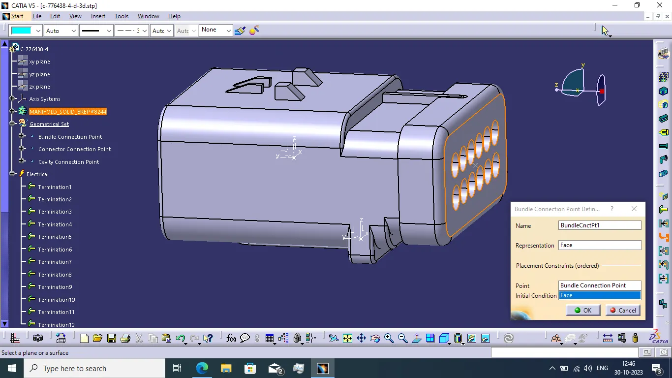
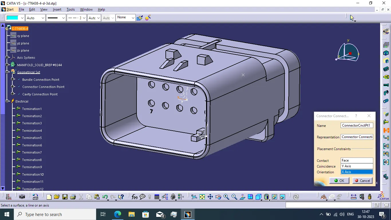
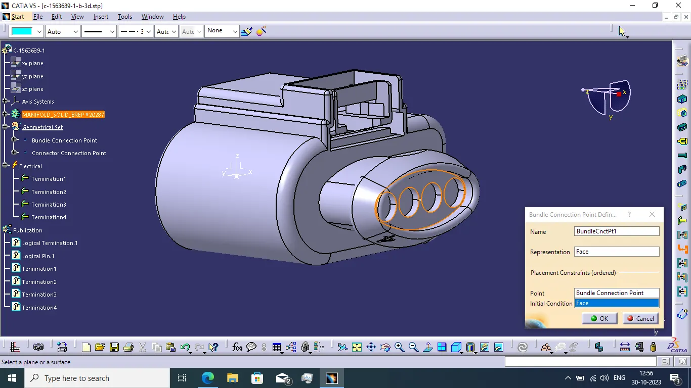
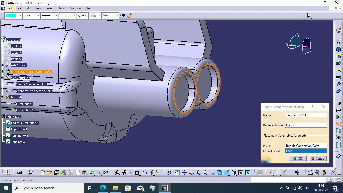
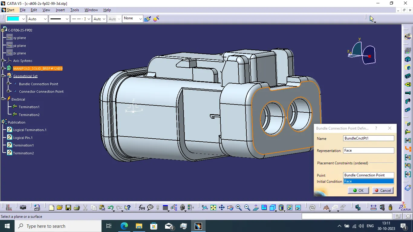
- We create the bundle connection point, connection connector point and axis system of all connectors.
- Now define bundle connection point and connector connection point. And add connectors to the catalogue file.
- And also define clips as a support part and define the entry and exit point of the clip.
C-776438-4-d:
C-1563689-1-b:
C-173090-2-a:
DT06-2S-FP02:
C-1924487-2-d:
FURR TREE CLIP:
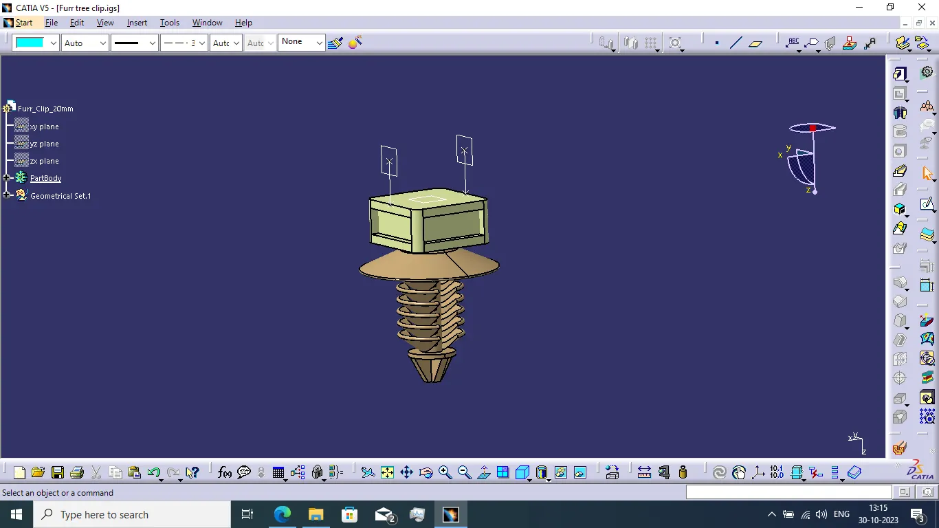
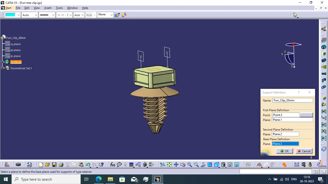
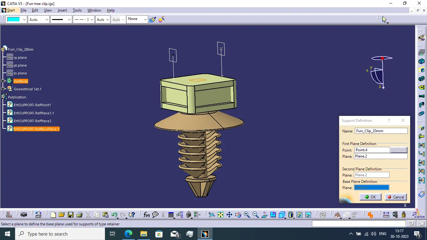
- When completed to define all required component electrically then we create the wiring harness context assembly and add the given back door as below the context assembly.
- Next we want to create geometrical bundle assembly under the context assembly.
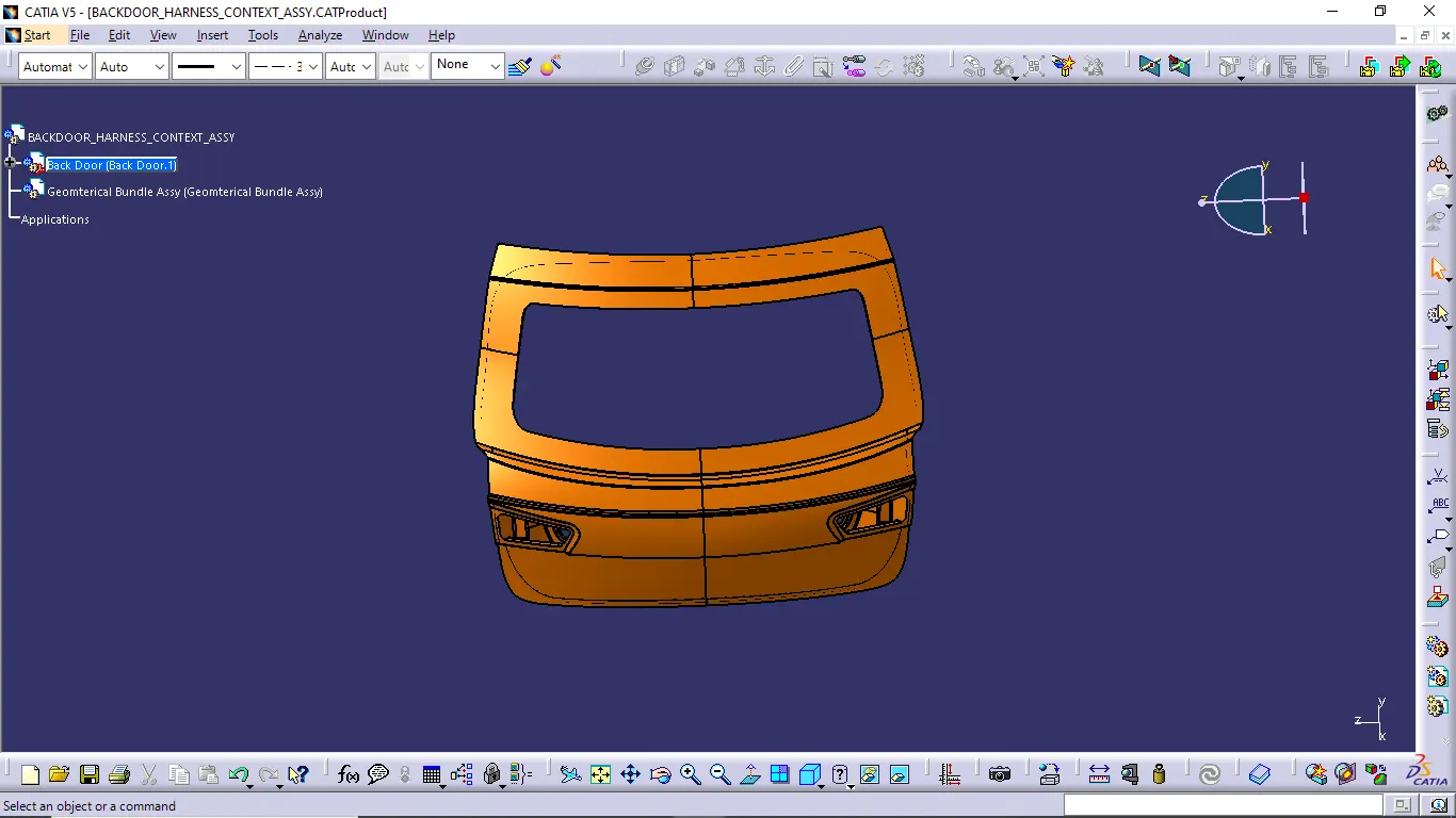
- Now we want to add all connectors and support parts below the geometrical bundle assembly file and placed it to the desired positions.
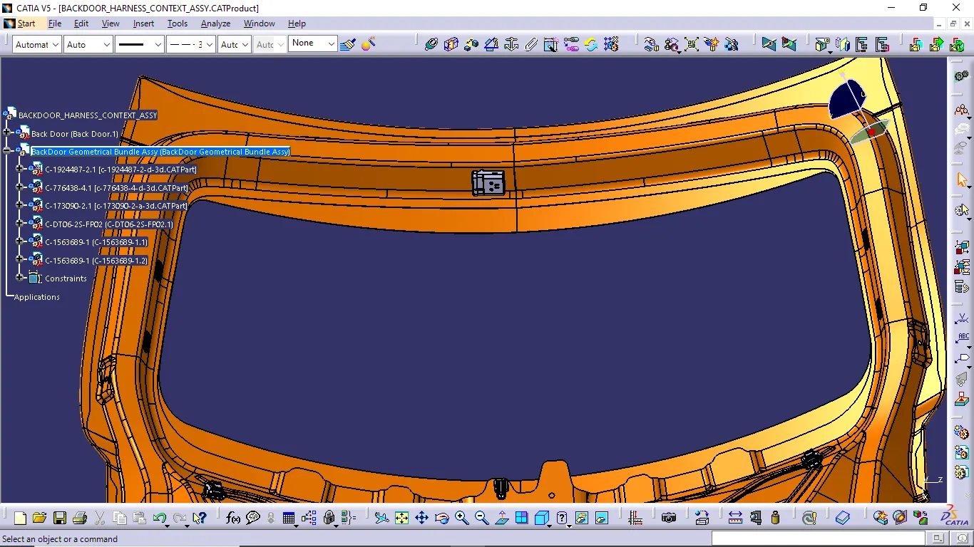
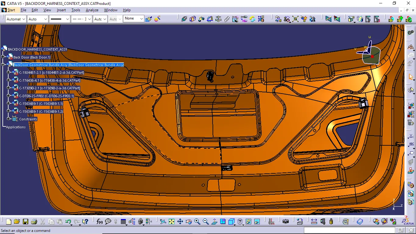
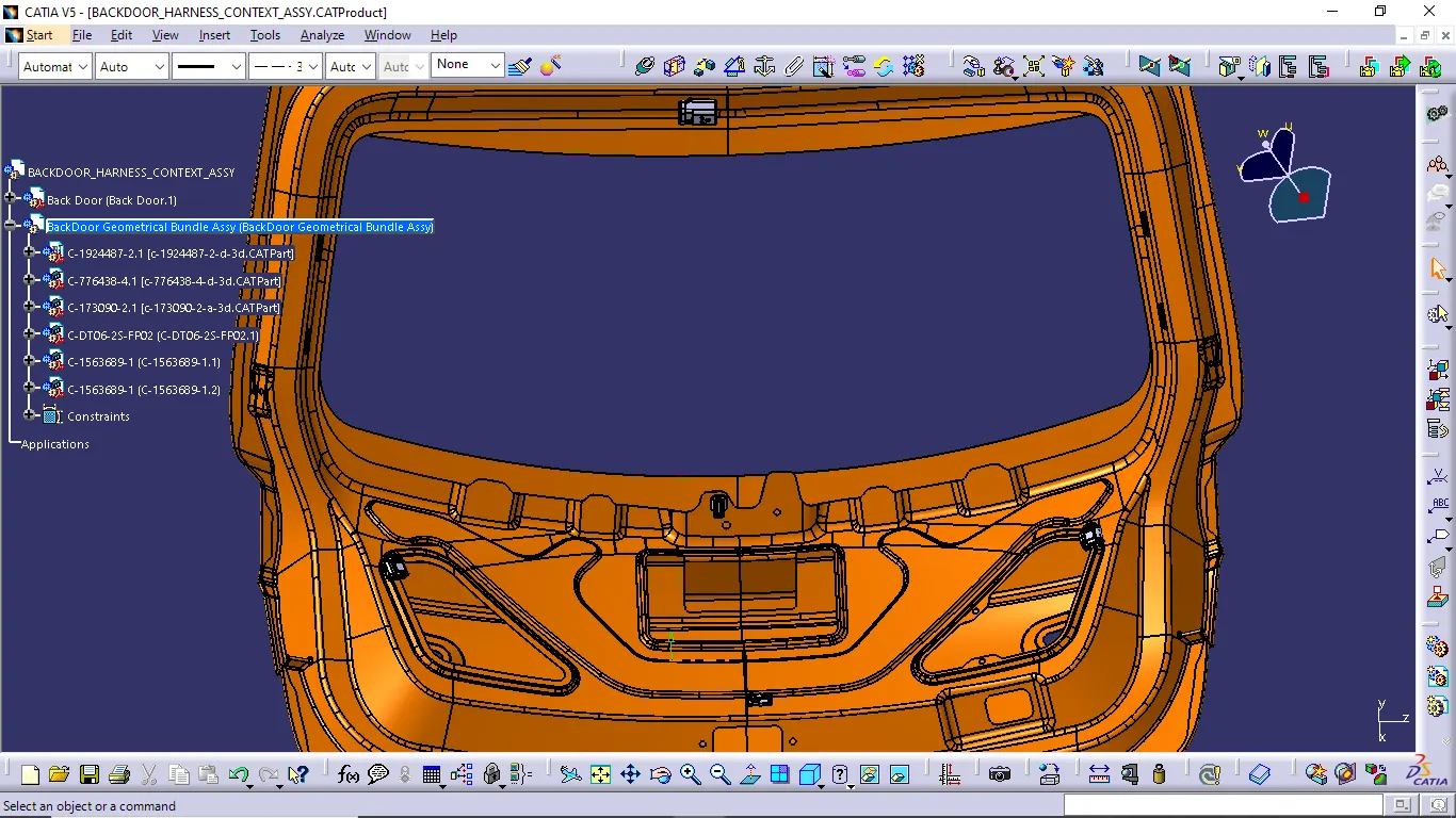
- Now add furr tree clip desired places for the use of creating wiring harness comfortability and route the bundle segment without any fouling of back door panel edges and other components.
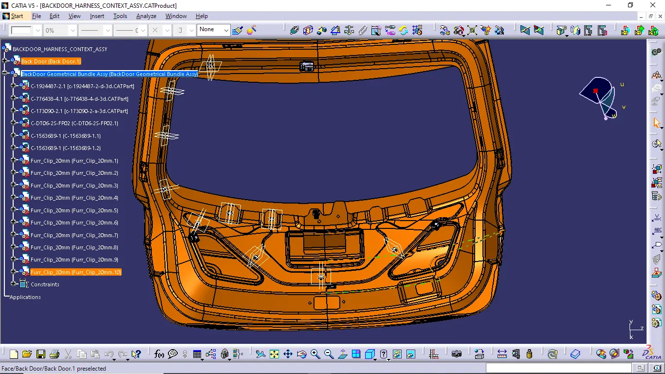
- When completed to place all required components as its desired positions next we want create the harness.
- Go to electrical harness assembly workbench and use the command geometrical bundle and select backdoor geometrical bundle assy product file to change it to the harness routing available file.
- Now we able to create the bundle segment and route the back door using multi-branchable document command.
- When selecting multi-branchable document command branch definition dialog box is opened and give the bundle diameter and select two component to create the branch.
- Follow the above steps to create the branches to connect all connectors and clips. And give slacks when it requires.
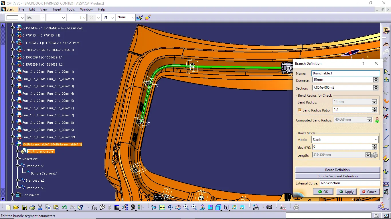
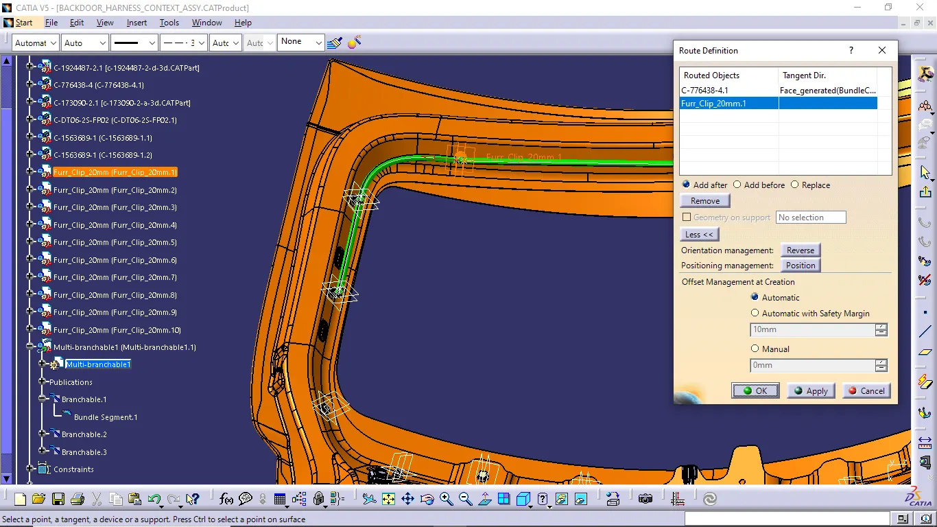
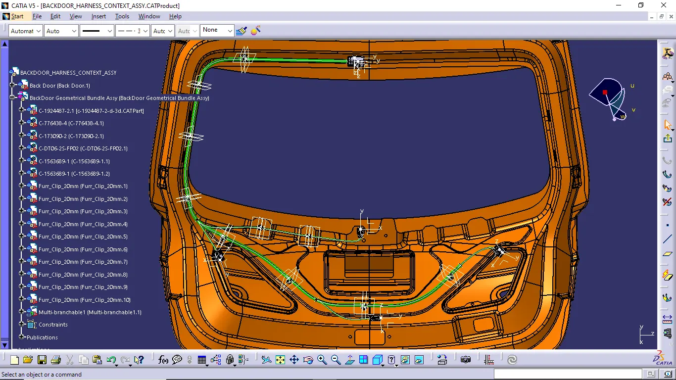
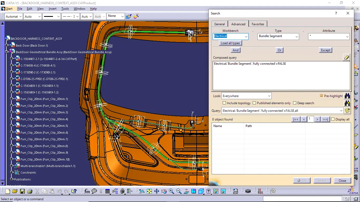
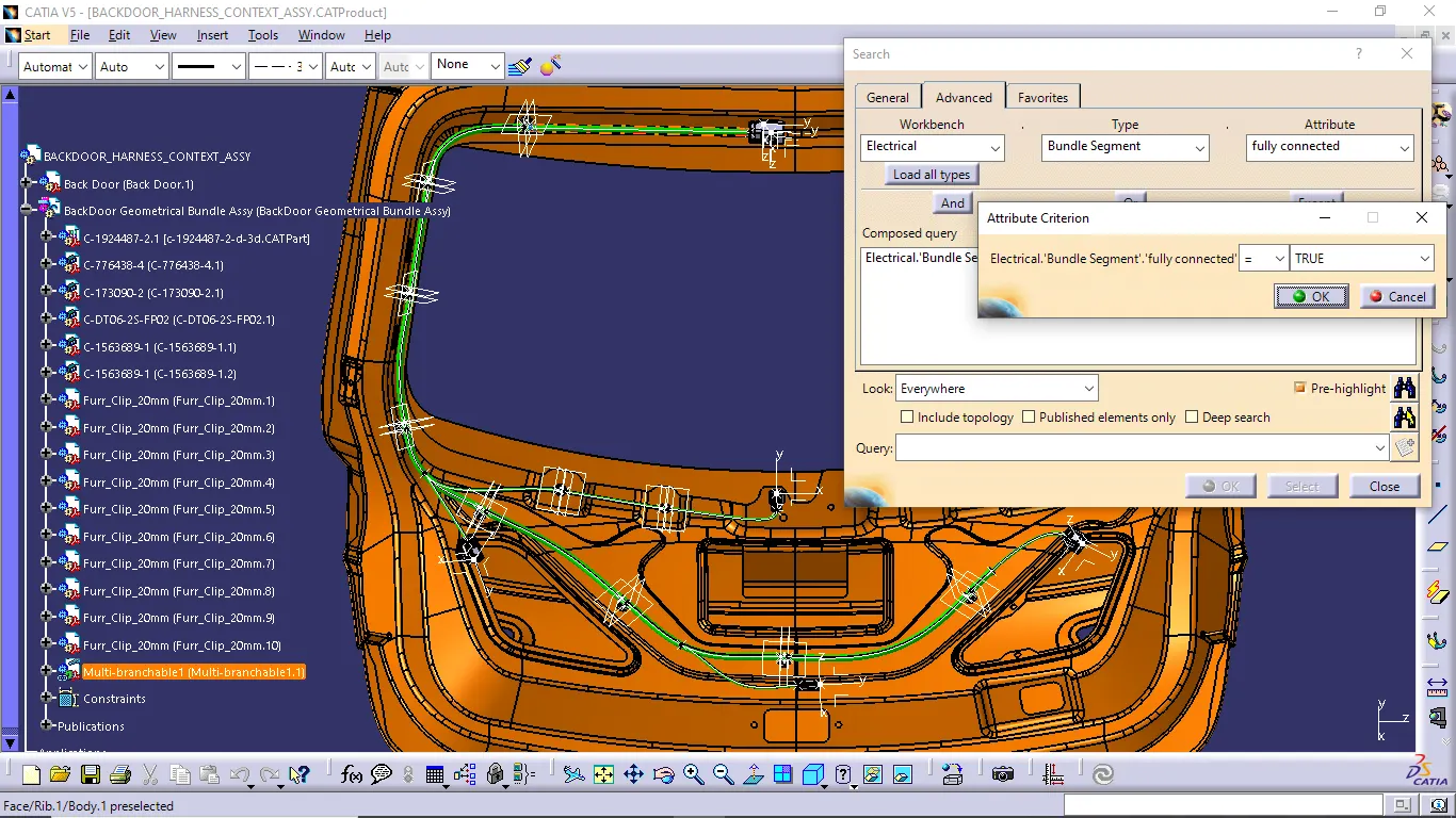
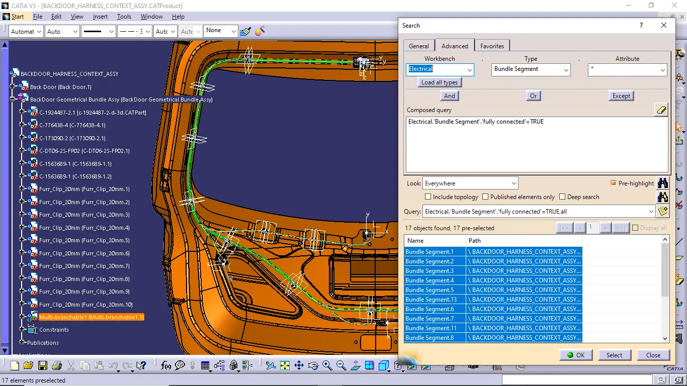
- When we completed to creating wiring harness bundle segment, next we want to check the harness continuity. So we follow the below steps to check the harness bundle continuity.
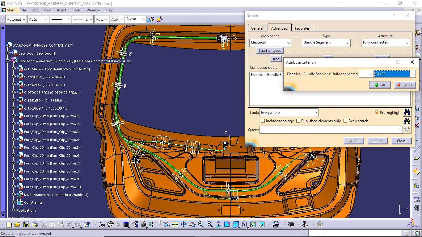
- Go to edit and select search option. Now search box is opened and go to advance option and select workbench as an electrical, type as a bundle segment and attribute as fully connected then give true or false condition and select search now we get a result highlighted. If any discontinuity in bundle segment is presented to indicate in flase condition. so we solve the discontinuity of the branch.
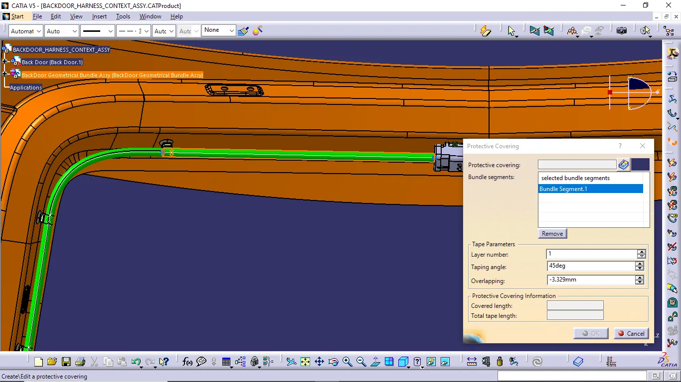
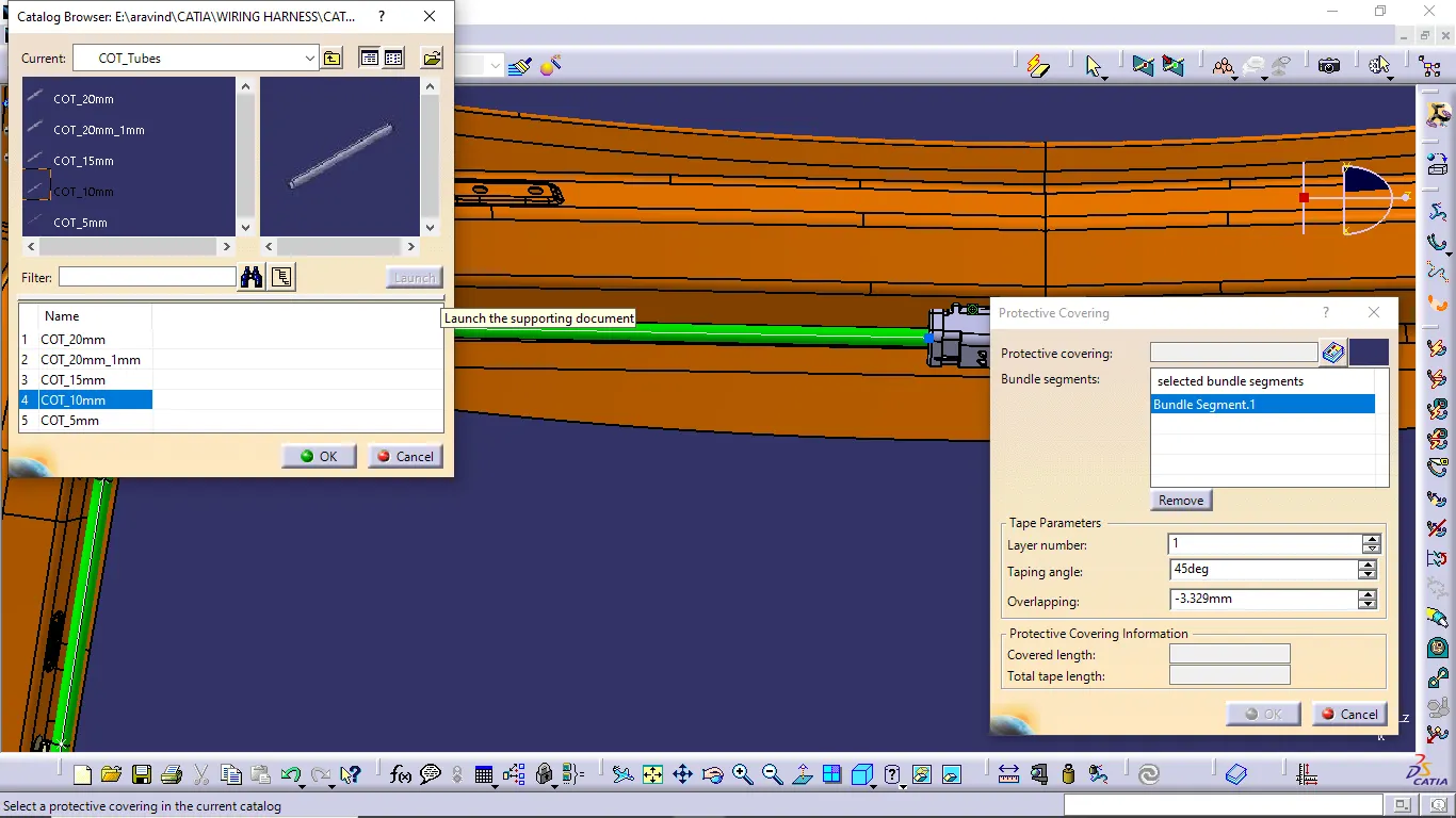
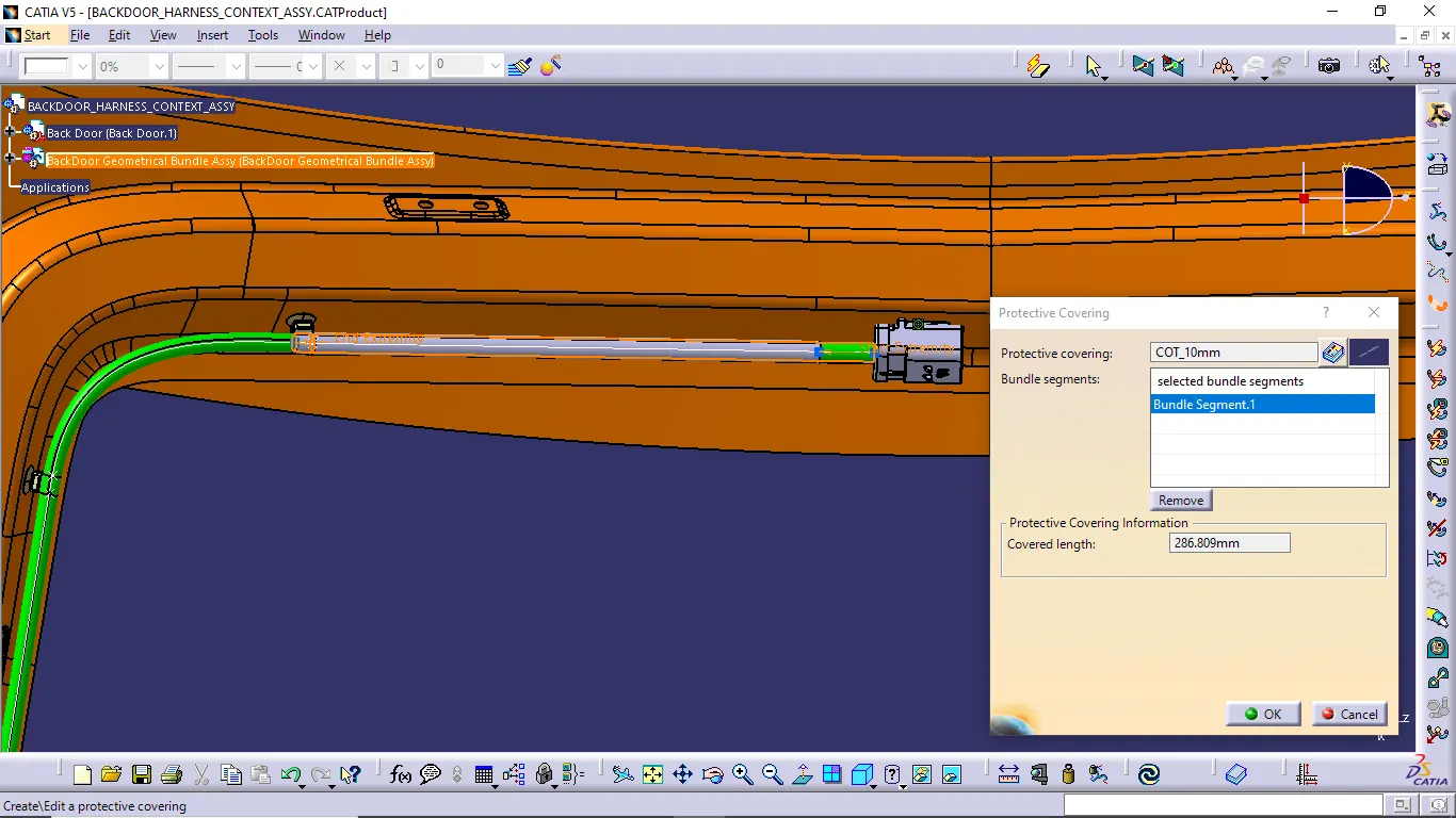
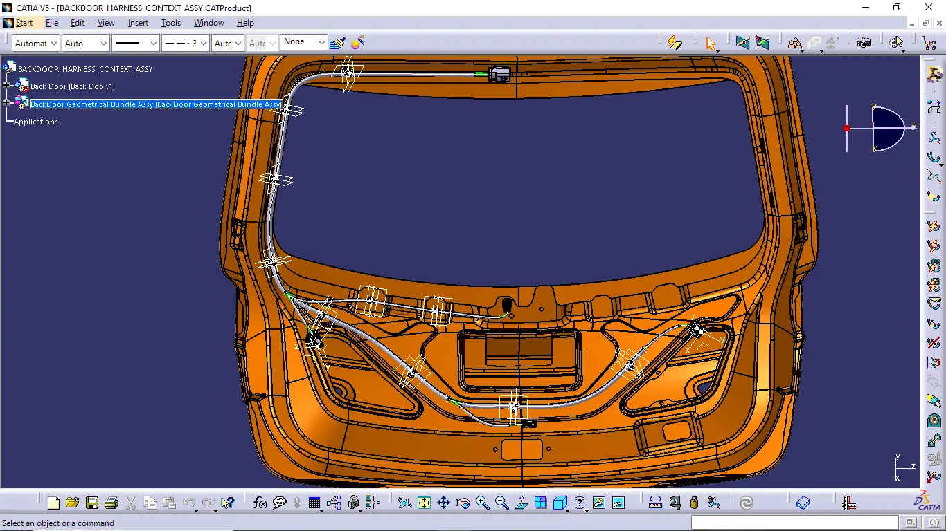
- Next we give the protection covering for required branches with COT tubes or other protection covering to the basis of protection reasons. In this back door harness wiring we need COT tube covering for protection is enough.
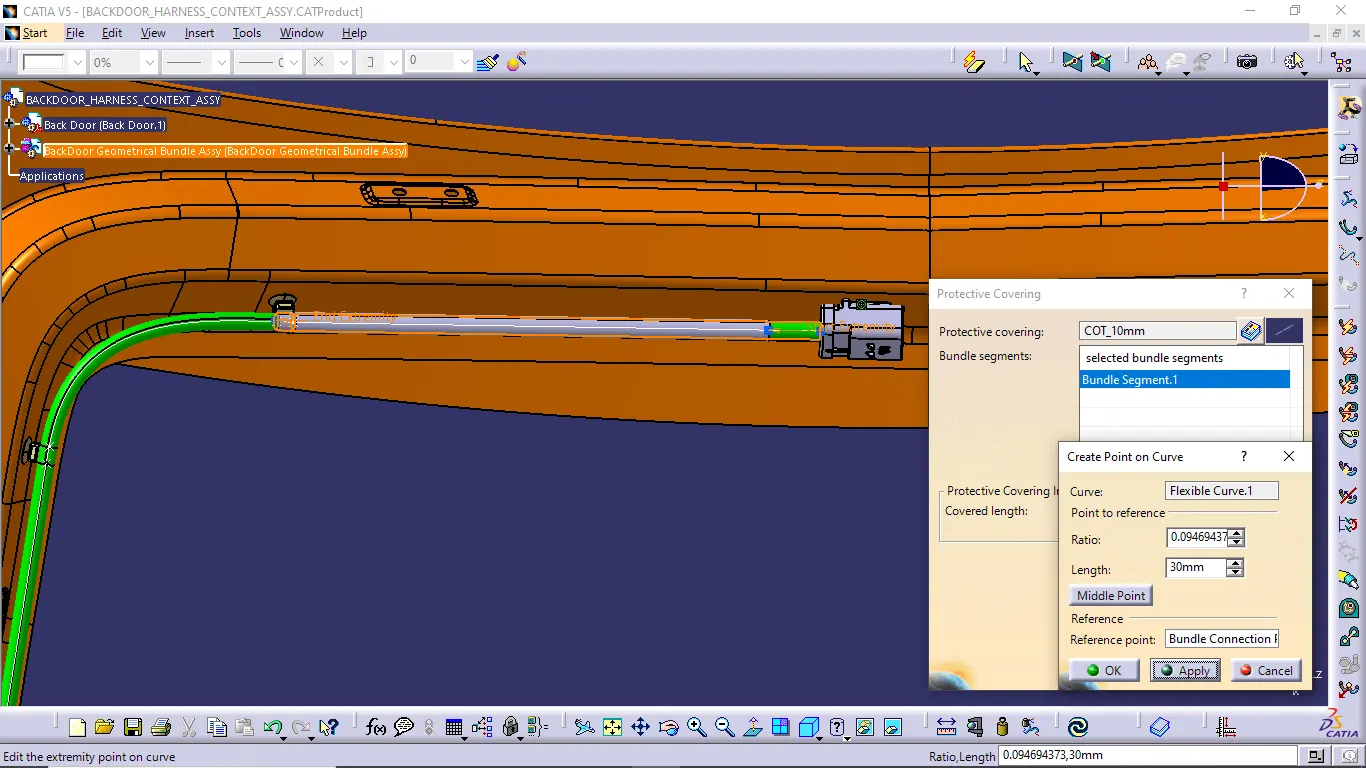
- For doing the protection covering process follow the below steps. And give the extremity value near the connector is 30, in other places give extremity limit if needed.
HARNESS FLATTENING:
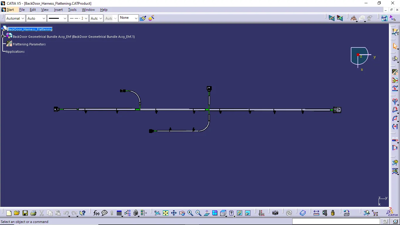
- Finally we complete the routing process. Now we go to the electrical harness flattening workbench and do the flattening of the harness.
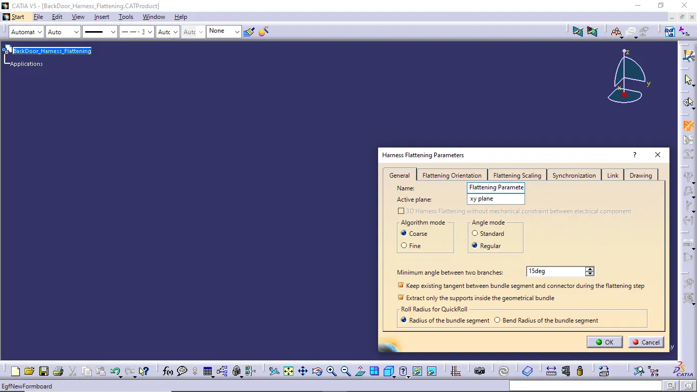
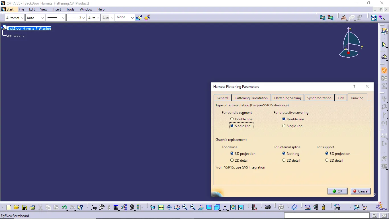
- In first we want to create new product file and use the harness flattening paramenters command and give and edit the option from the opened dialog box for our requiredment.
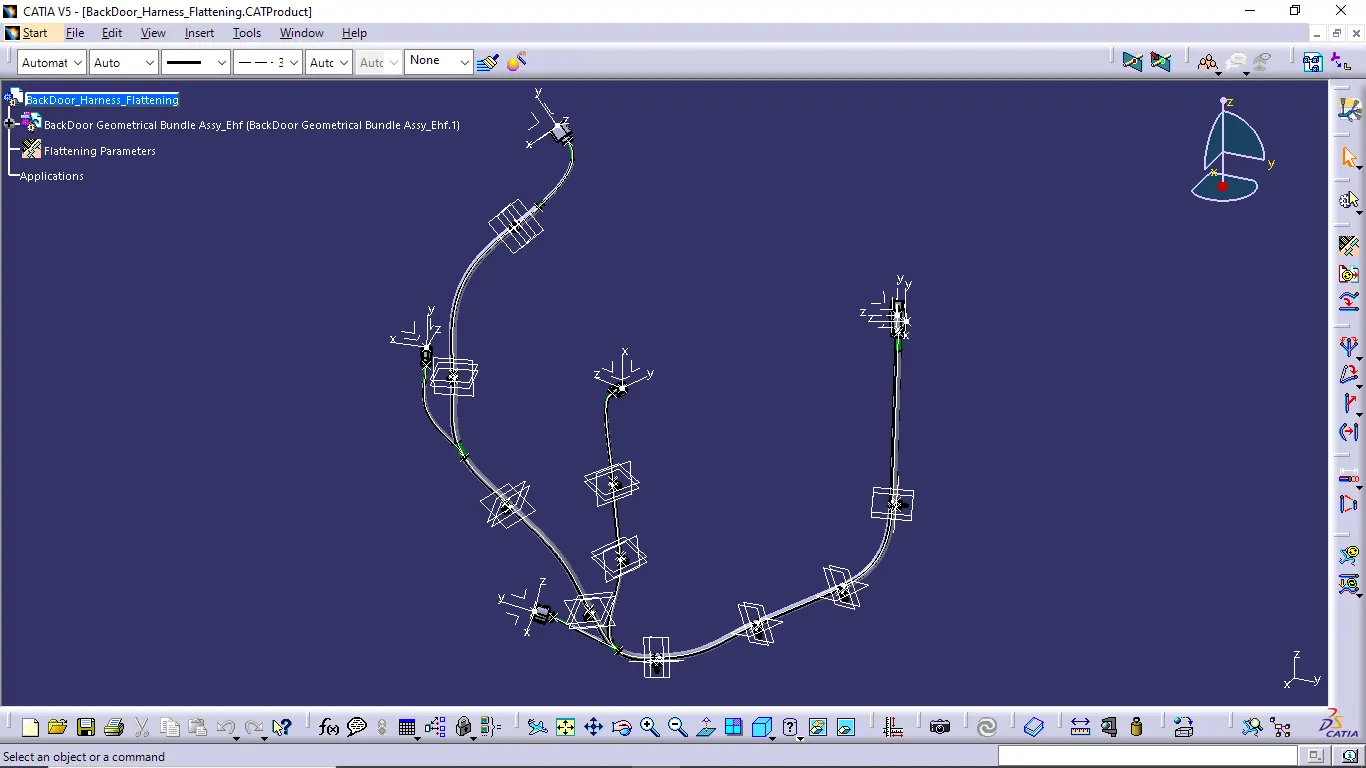
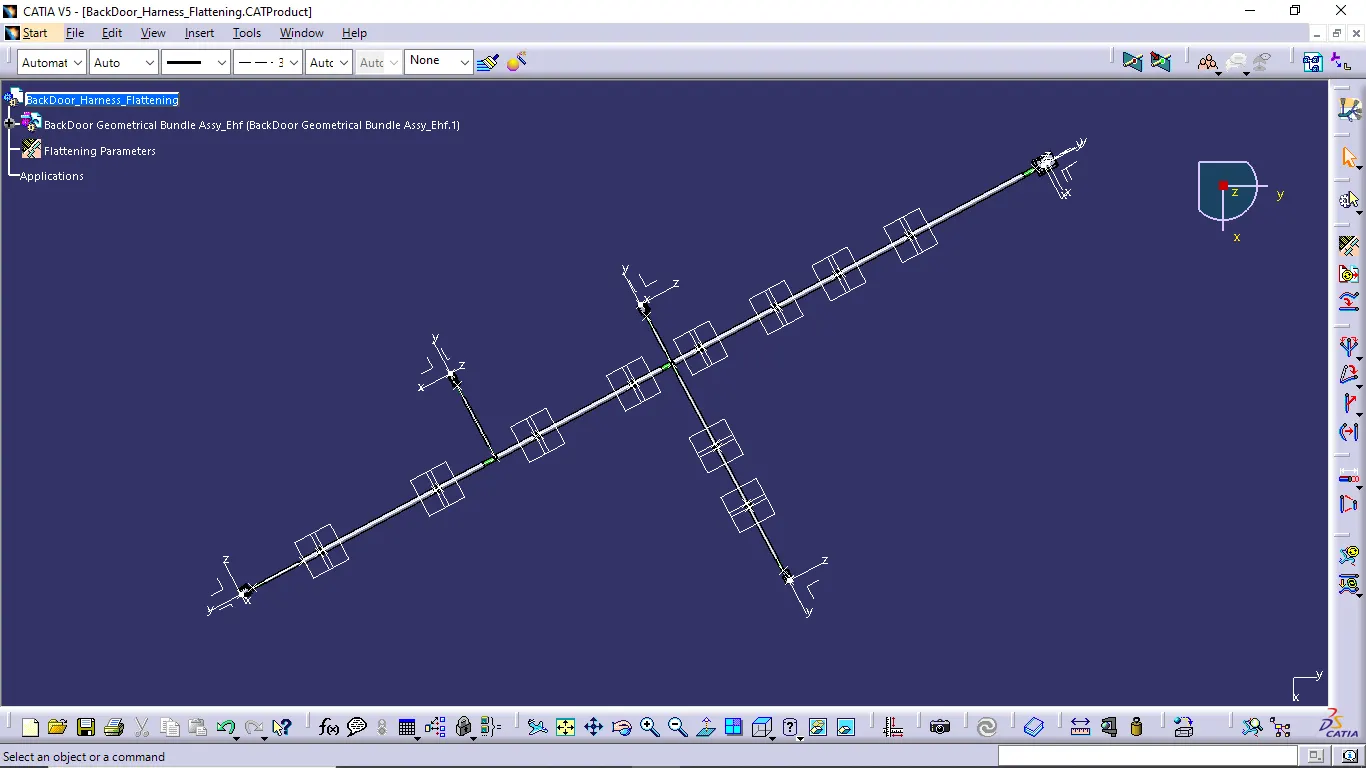
- Now select the extract command and select backdoor geometrical bundle assembly and do the flatten of the extracted harness routing file.
- Then use other commands to simplify the flatten view. Other feature commands like bend, rotate, roll and etc.
FLATTEN VIEW DRAWING:
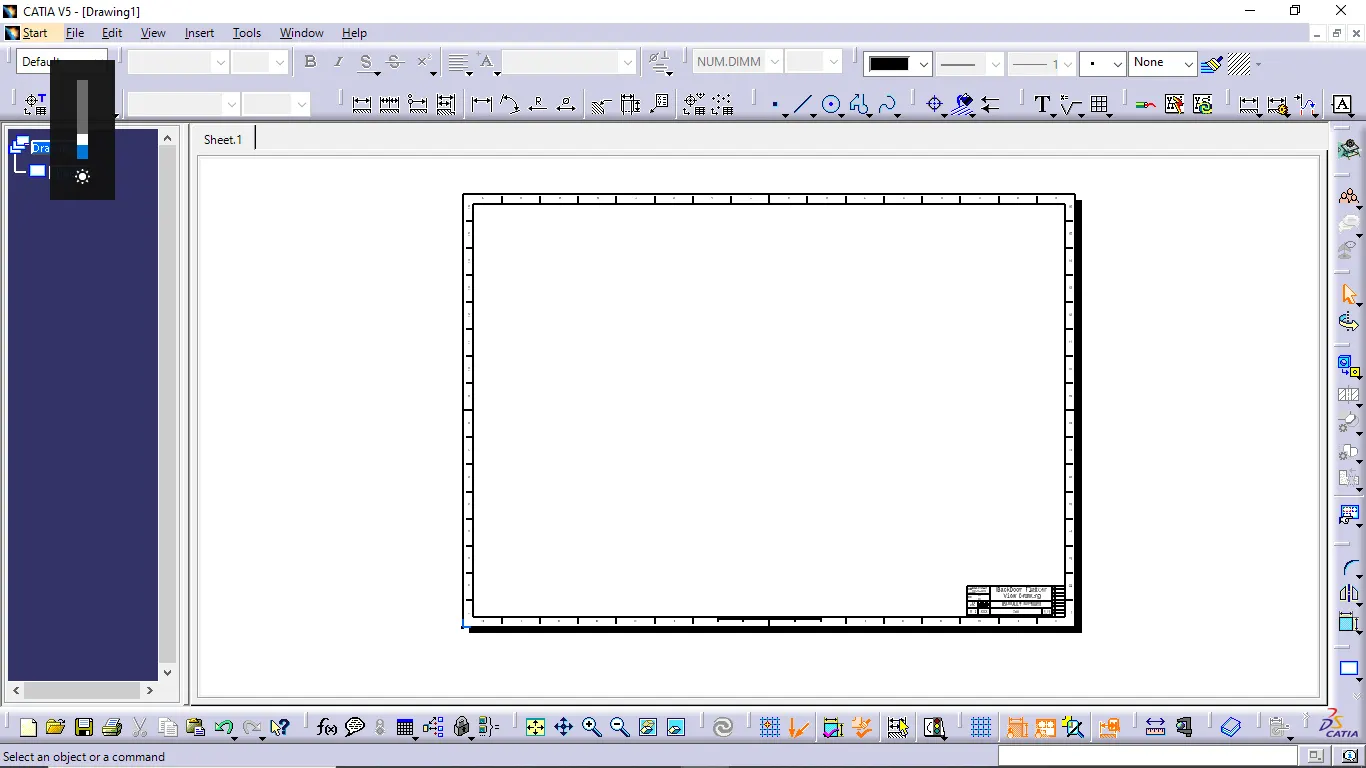
- We are creating new drawing file and define and edit all required drawing parameters.
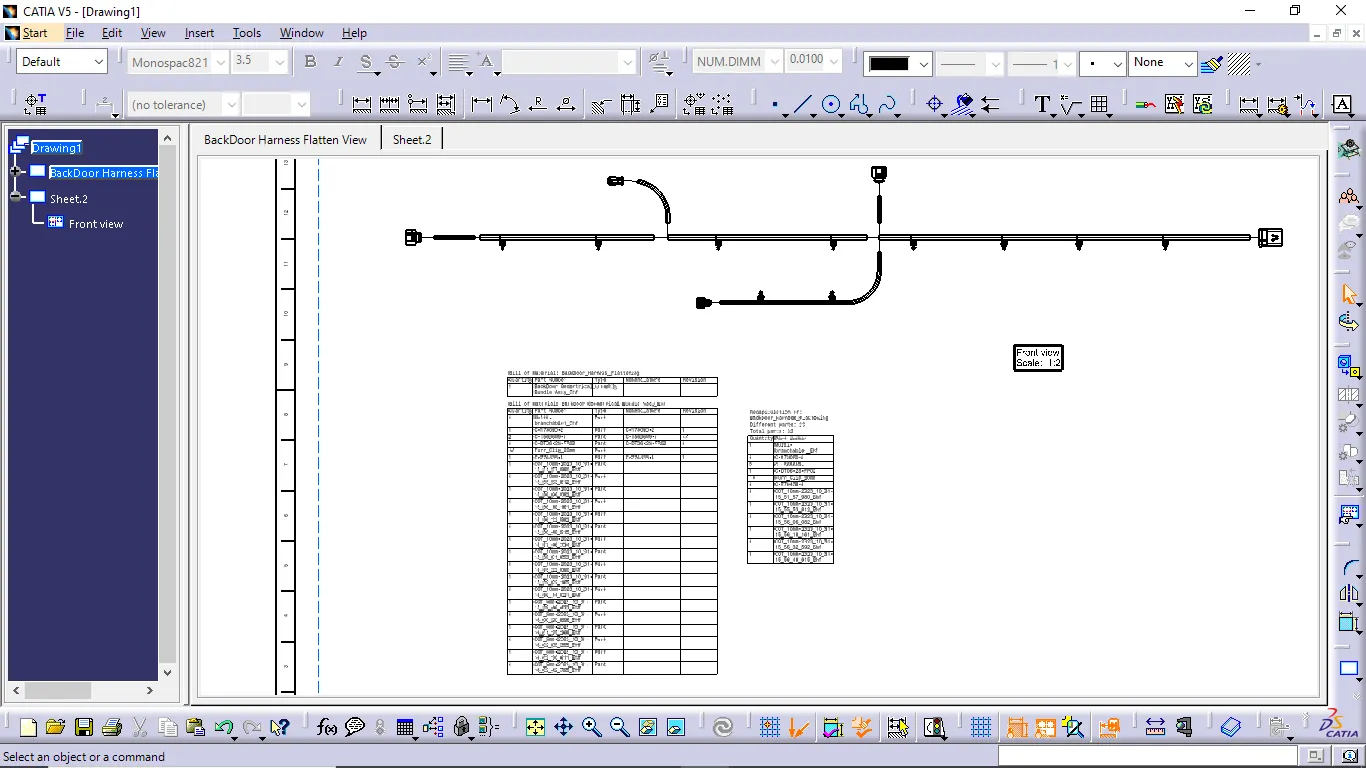
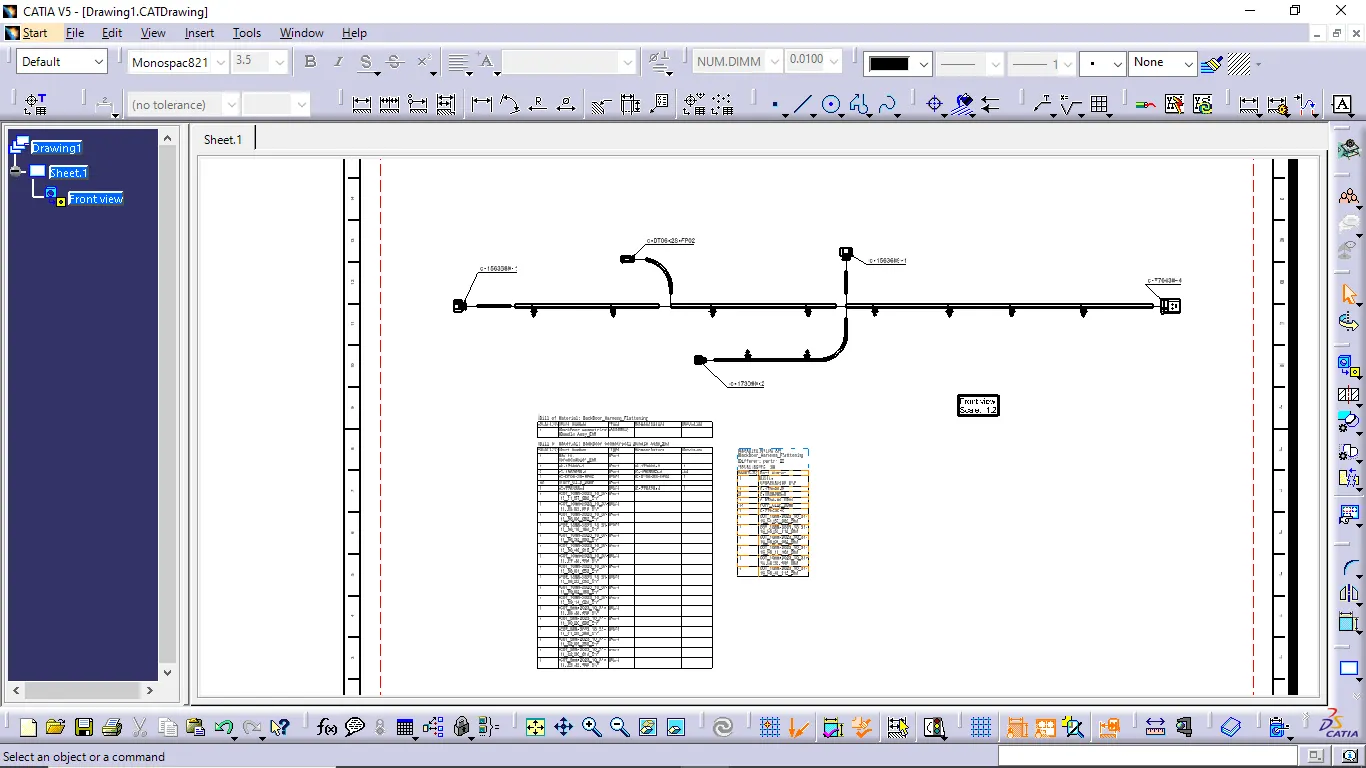
- Now we insert the required harness flatten view using front view command. In drawing properties 3D wireframe option is always ON in the Dress up settings.
- Then we define required parts in the drawing.
CONCLUSION:
Finally, i completed the routing the wiring harness of given car back door part and prepare the flattten view drawing in CATIA V5. And also apply the all packaging rules and industry best practices.