Project 2
1} AIM :- ROUTE THE WIRING HARNESS ON THE GIVEN CAR BACKDOOR AND PREPARE FLATTEN VIEW DRAWING IN CAD MODELING SOFTWARE CATIA-V5.
2} OBJECTIVE :- The objective of this project is to route the wiring harness and prepare flatten view drawing for the backdoor of the car. All types of packaging rules have to be considered while routing the harness and industry based practices shall be demonstrated in harness design. All necessary details like clearance, clipping/clamping selection, harness fixing requirements, harness continuity should be provided in order to design the wiring harness.
3} ASSUMPTIONS:-
- Wiring harness should be routed in such way that it is easy to assemble and access.
- Easy manufacturing, installation, removal and maintenance have to be considered while designing the wire harness.
- Wiring Harness should be kept away from sharp environment like edges, corners etc.
- Avoid harness routing and clipping in the blind zones or hard to reach areas during harness assembly or service.
- Provide additional slack if needed according to the surrounding and harness bending requirement. If harness is passing through the closures/doors or tail gates then envelope dimensions during opening and closing of doors shall be considered to provide the slack. Check the harness slack requirements with open and close conditions to avoid excess slack.
- Routing through small structural holes and openings shall be avoided. To minimize chaffing and handling of the wiring harness during installation.
- It should be make sure that there is no case of fouling while designing the wiring harness in the CAD environment. Additional mounting equipments like clips/clamps may be used to avoid fouling.
- Use of rubber grommet is recommanded if harness is passing through sheet metal panels. Example- firewall, passing to door, tail gate etc.
- The branch length should be greater than 50mm.
- The minimum distance between the clip and branch point should be at least 25mm.
- The minimum distance between the two branch points should be at least 50mm.
- Clips/clamps used for the wiring harness should be easily available in the market to avoid extra cost for custom mounting solutions.
4} DESIGN METHODOLOGY :-
1. DOWNLOAD THE 3D CAD DATA OF ALL THE REQUIRED CONNECTORS AND MOUNTINGS FROM THE SITE www.te.com .
2. DEFINE ALL THE CONNECTORS AND MOUNTINGS CLIPS ELECTRICALLY BY DEFINING ALL OF ITS PROPERTIES.
3. ADDING ALL THE CONNECTORS TO CATLOGUE DOCUMENT.
4. CREATE NEW PRODUCT FILE IN THE ASSEMBLY WORKBENCH NAMED AS BACKDOOR CONTEXT ASSEMBLY , USING TOP DOWN APPROACH THIS WILL BE TOP LEVEL OF PRODUCT FILE INSIDE THIS PRODUCT FILE CREATE GEOMETRICAL BUNDLE FOR ALL THE CONNECTORS , CLIPS , CLAMPS AND WIRE HARNESS ELECTRICAL BUNDLE AND ADD CAR BACKDOOR ASSEMBLY , L SHAPE BRACKET TO THE CONTEXT ASSEMBLY.
5. ORIENTATION OF ALL THE CONNECTORS , CLIPS , P-CLAMP , L SHAPE BRACKET AT APPROPRIATE LOCATIONS.
6. ROUTING THE HARNESS THROUGH BACKDOOR , BUNDLE CONNECTIVITY CHECK .
7. USE OF COT-TUBES FOR BEST INSULATION AND PACKAGING , FLATTENING AND DRAWING CREATION.
NOW, HERE WE HAVE TO ROUTE WIRING HARNESS FOR TWO TAIL LIGHT LEFT AND RIGHT, ONE FOR NUMBER PLATE AND ONE FOR BOOT OPENER. HERE, WE ARE USING TWO 8 POLE CONNECTOR AND TWO 2 POLE CONNECTORS.
A CAR BODY ALSO HAVE AN INTERCONNECTION CONNECTOR WHICH WILL CONNECT THE WIRING HARNESS OF BACKDOOR OF THE CAR BODY TO MAIN HARNESS OF THE VEHICLE.
HERE, WE ARE USING 12-POLE ELECTRICAL CONNECTOR WITH A MOUNTING CLIP AS AN INTERCONNECTION CONNECTOR.
THE BEND RATIO FOR ALL THE BUNDLE SEGMENT IS CONSIDERD TO BE 1.4 .
- 5} PROCEDURE :-
- STEP 1 :-
- We have created context assembly for the backdoor of the car as main assembly as shown in above figure.
- This context assembly contains the 3D cad data for the backdoor of the car and car backdoor harness geometrical bundle.
- DEFINING THE CONNECTORS , CLIPS , CLAMPS ELECTRICALLY :-
-
Here we have inter connection connector it require mounting clip for mounting the connector .so cavity connection point should be defined for this connector. .
(A) CREATE MID POINT IN BETWEEN THE TWO POINTS OF CONTACT FACE WHICH WILL BE NORMAL TO THE WIRE BUNDLE INSERTION :-
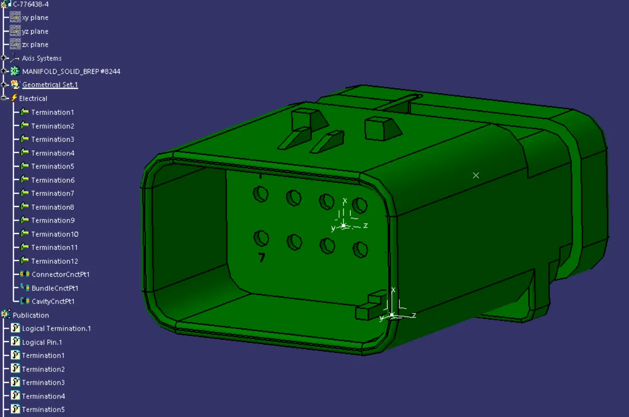
(B) CREATE AXIS SYSTEM WITH RESPECT TO THE POINT CREATED AND DEFINE THE Y AXIS OF AXIS SYSTEM POINTING TOWARDS THE FRONT FACE OF THE CONNECTOR , Z AXIS SHOULD BE POINTING ACROSS THE CONNECTOR FROM LEFT TO RIGHT , X AXIS SHOULD BE POINTING IN THE DIRECTION TOWARDS THE LOCKING MECHANISM OF THE CLIP.
(C) BUNDLE CONNECTION POINT :-
CREATE MID POINT ON THE BACK FACE USING THE MIDDLE CIRCLE OF THE CONNECTOR WHICH WILL BE NORMAL TO THE BUNDLE INSERTION.
(D) CREATE CAVITY CONNECTION POINT ON THE MIDDLE POINT OF THE CURVE OR LINE LAYING ON THE CONTACT FACE OF THE CONNECTOR TO THE CAVITY.
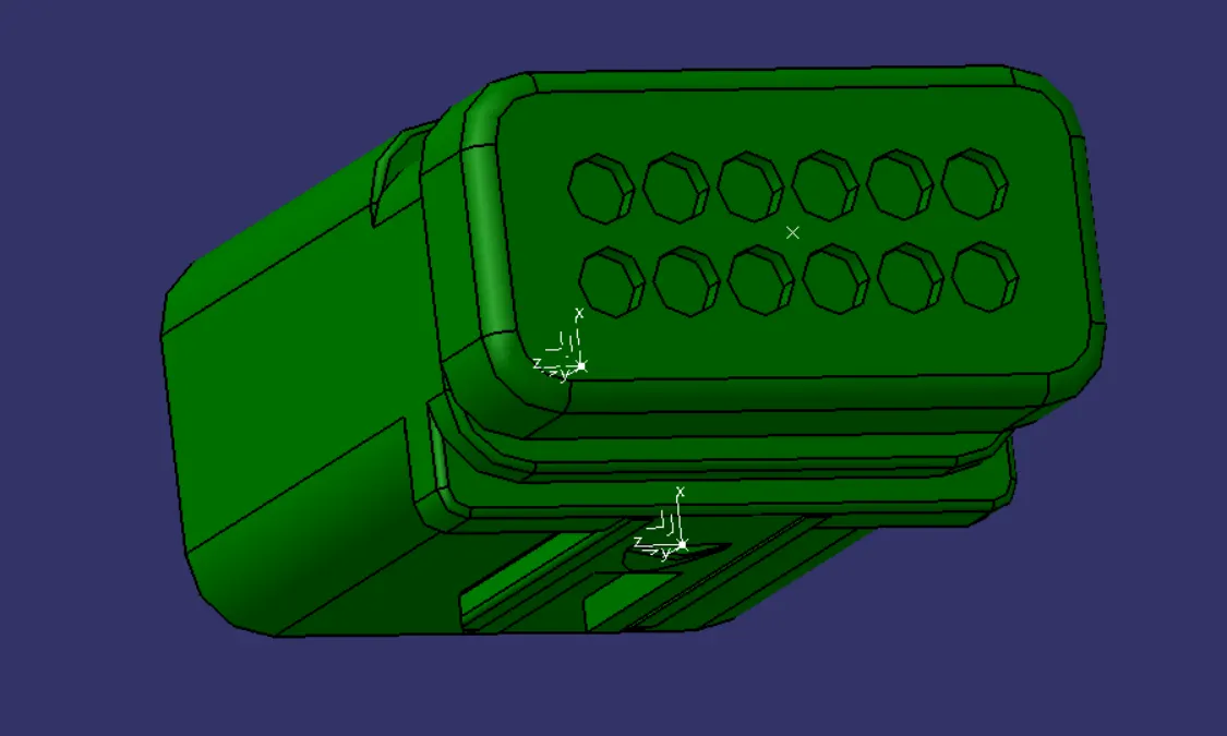
(E) CREATE CAVITY CONNECTION AXIS SYSTEM.
(F) SWITCH TO ELECTRICAL PART DESIGN.
DEFINE THE PART AS A CONNECTOR IN CATIA , THEN PROVIDE NO. OF TERMINATIONS AS 12 , BECAUSE THIS CONNECTOR CONSIST OF 12 ENTRY POINTS FOR WIRE.
(G) DEFINE BUNDLE CONNECTION POINT.
(H) DEFINE CONNECTOR CONNECTION POINT.
(I) DEFINE CAVITY CONNECTION POINT.
MOUNTING CLIP :-
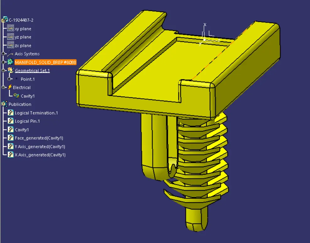
- Define the mounting clip electrically by defining all the properties .
Define the clip as mounting equipment using mounting equipment command. Select cavity command and define the parameters.
- A) CREATE MID POINT USING THE UPPER LINE LAYING ON THE CONTACT SURFACE OF THE CAVITY.
- B) CREATE CAVITY CONNECTION POINT.
- C) CREATE CAVITY CONNECTION AXIS SYSTEM AND ORIENT THE CAVITY CLIP AS THE SAME WAY AS CONNECTOR.
- D) SWITCH TO ELECTRIC PART DESIGN AND DEFINE THE PART AS MOUNTING EQUIPMENT.
- E) DEFINE CAVITY CONNECTION POINT.
ELECTRICAL ASSEMBLY DESIGN :-
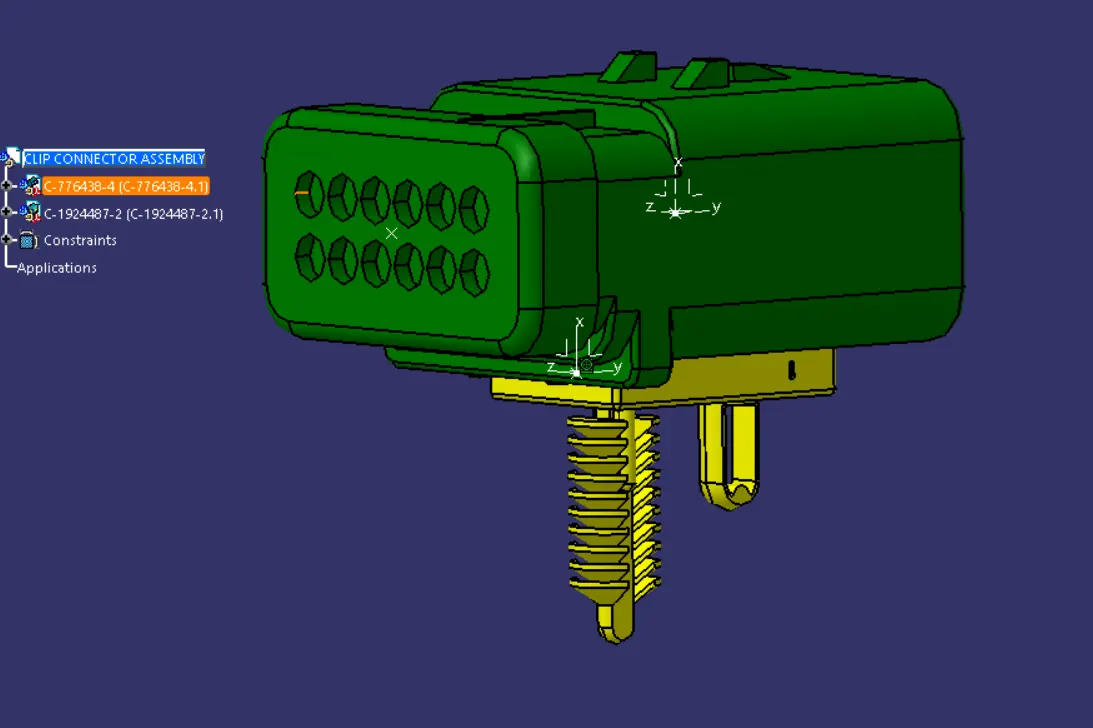
(A) CREATE ASSEMBLY IN ELECTRICAL ASSEMBLY DESIGN COPY BOTH THE CONNECTOR AND THE CAVITY CLIP PASTE IT TO THE ELECTRICAL ASSEMBLY.
(B) SELECT DEFINING ELECTRIC CONNECTION, USE CONNECT ELECTRICAL DEVICES COMMAND.
(C) SELECT CAVITY AND CONNECTOR.
STEP 2 :-
DEFINING 2-POLE AND 8-POLE CONNECTORS ELECTRICALLY :-
- Here, we will use 2-Pole and 8-Pole connectors for this assembly and for that we have downloaded these connectors from TE.Com
- We should have to define it electrically that is to define geometrical parameters, bundle connection point and connector connection point same as defined earlier for inter connection connector.
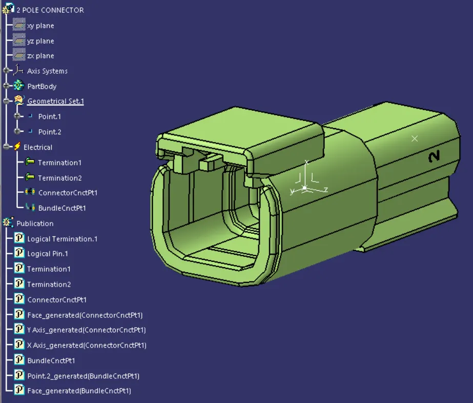
- Here, we have defined two 2-Pole connector electrically for number plate lights and boot opener of the car.
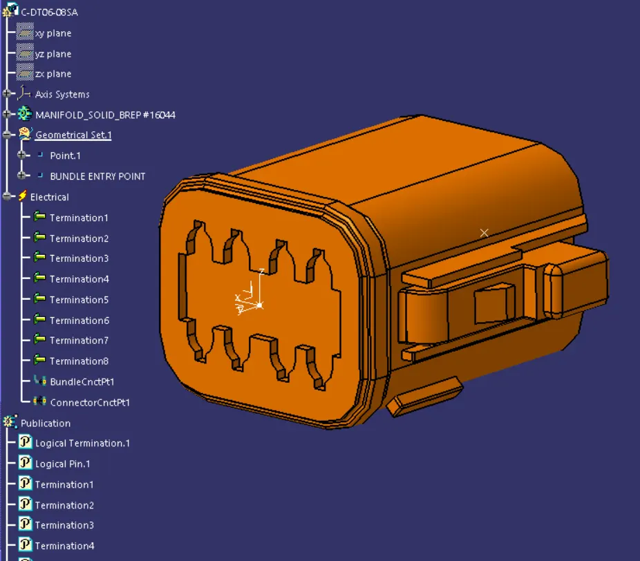
Here, we have defined two 8-Pole connectors electrically for two (LEFT,RIGHT) tail lights of the car.
STEP 3 :-
DEFINING THE CLIPS AND CLAMPS FOR BUNDLE SUPPORT AND ROUTING :-
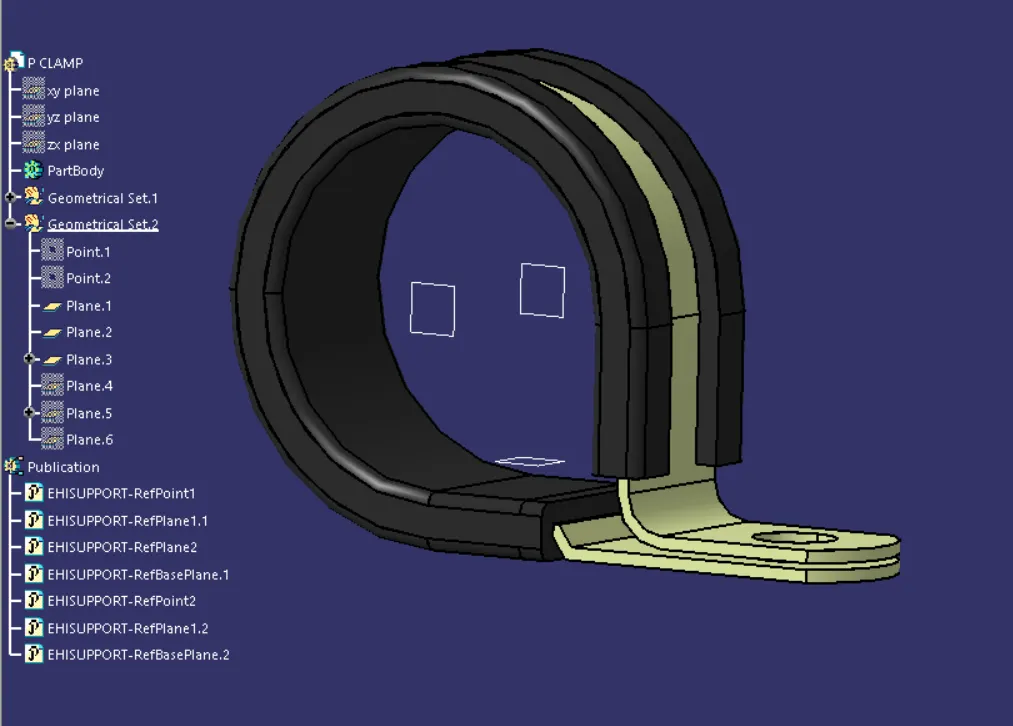
P-CLAMP:-
A) CREATE TWO POINTS AT THE CENTRE OF THE ENTRY AND EXIT OF THE CLIP BY SELECTING POINT TYPE AS RADIUS OF CIRCLE.
B) CREATE PLANES AT THE ENTRY AND EXIT POINTS OF THE CLIP AND ANOTHER PLANE AT THE BASE FOR RESTING OF THE BUNDLE WHICH IS OFFSETED AT DISTANCE OF 2 MM FROM THE BASE .
C) SWITCH TO ELECTRIC PART DESIGN.
D) CLICK ON SUPPORT DEFINATION SELECT THE P CLAMP PART THEN , SELECT THE ENTRY POINT AND PLANE THEN, SELECT THE EXIT PLANE AND BASE PLANE.
E) AGAIN CLIK ON SUPPORT DEFINATION THEN, SELECT THE P CLAMP PART , THEN SELECT EXIT POINT,PLANE AND THE BASE PLANE AS SECONDAY PLANE IS TAKEN BY DEFAULT.
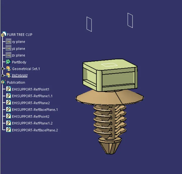
FURR TREE CLIP:-
A) First define geometrical parameters such as entry point, entry plane, exit point, exit plane and base plane .
B) Then switch to electrical part design workbench and define the fur-tree clip as support using support command and define the parameters.
SHEETMETAL BRACKET :-
Add sheet metal bracket in order to provide parking for the interconnection connector. Also, we have to make sure that the bracket is placed inside the context assembly and outside of backdoor and geometrical bundle assembly.
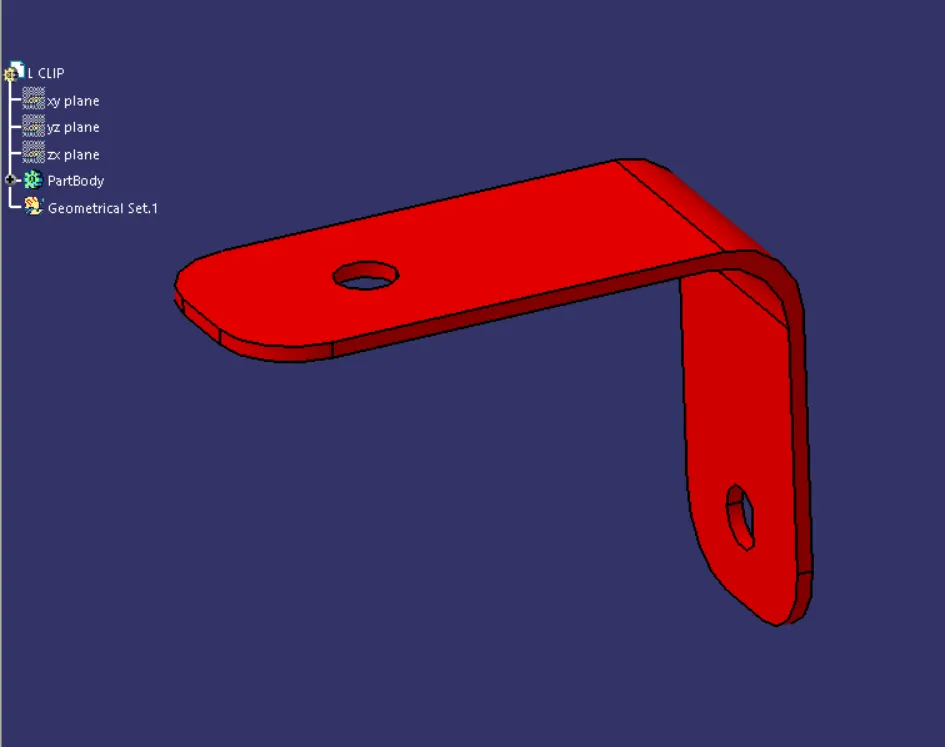
Add all the electrically defined components to the geometrical bundle.place the components at proper location for routing the harness
- Then switch into the electrical harness assembly workbench and Geometrical bundle product file should be electrically defined using the Define Geometrical bundle option .
STEP 4 :-
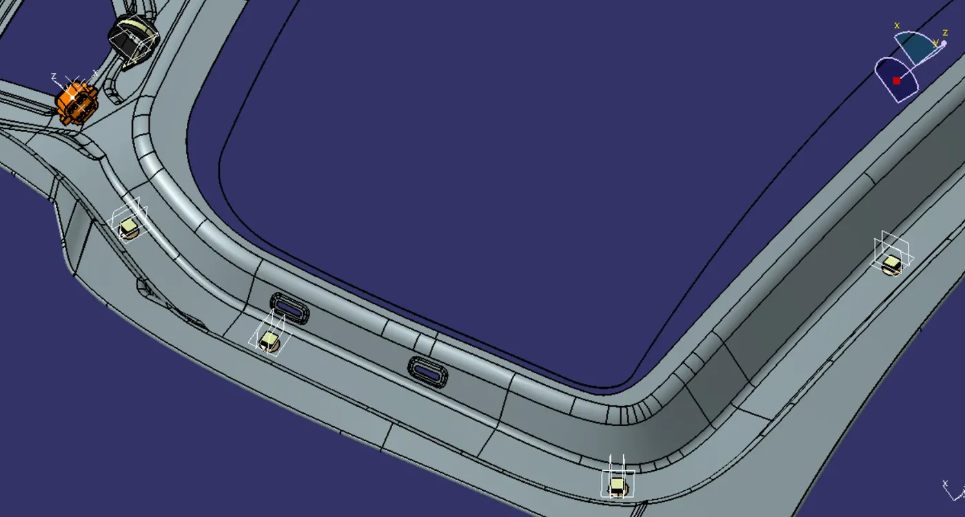
ADDING CONNECTORS TO THE LEFT, RIGHT TAIL-LIGHTS AND ANOTHER FOR THE BOOT OPENER, NUMBER PLATES LIGHT :-
- We have added both 2-pole connectors and 8-pole connectors inside the backdoor harness geometrical bundle assembly.
- We have used commands like manipulation, compass, snap and smart move to place all the 4 connectors to their desired location.
- We have placed all the connectors at their desired position as shown in below figures.
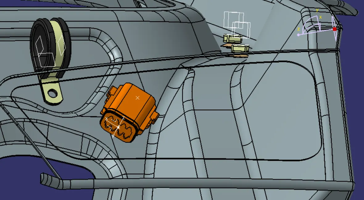
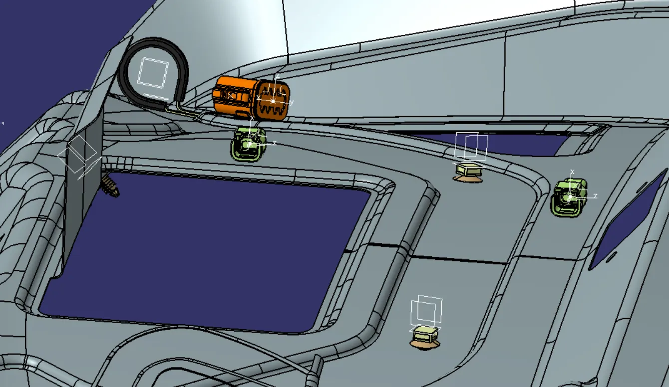
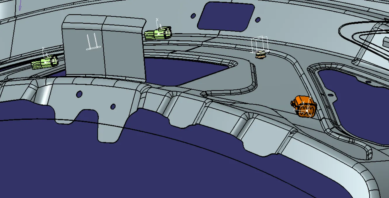
STEP 5 :-
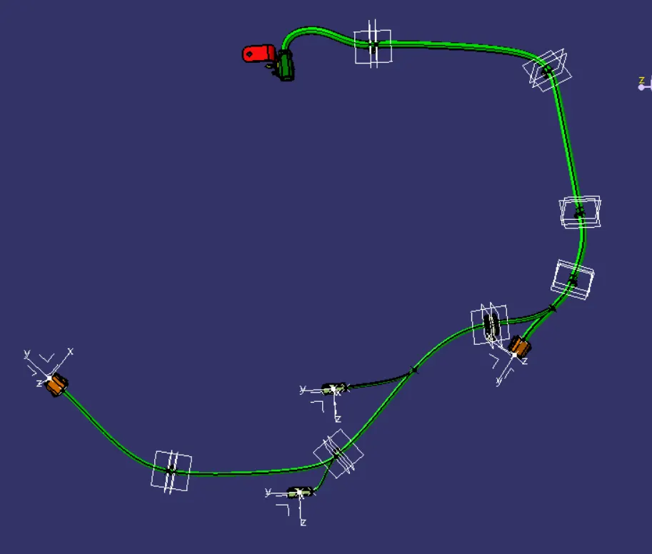
BUNDLE ROUTING :-
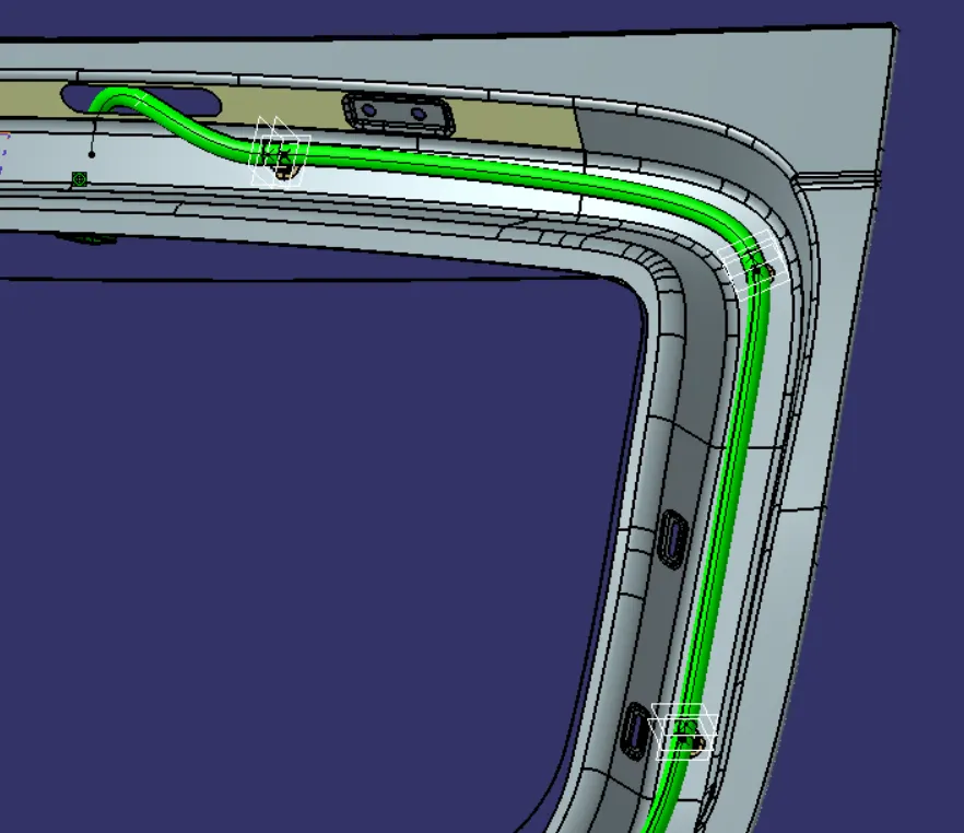
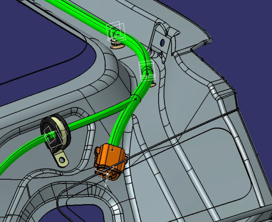
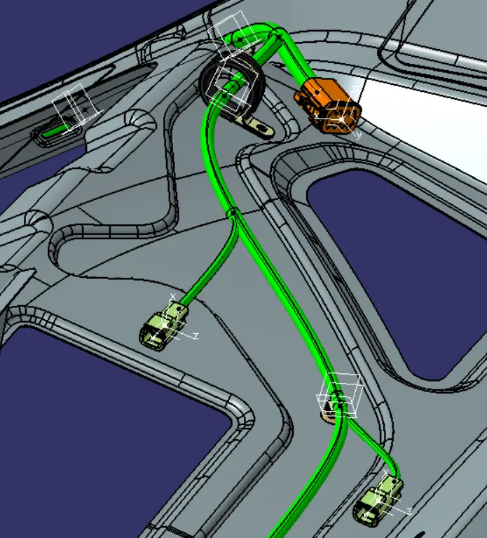
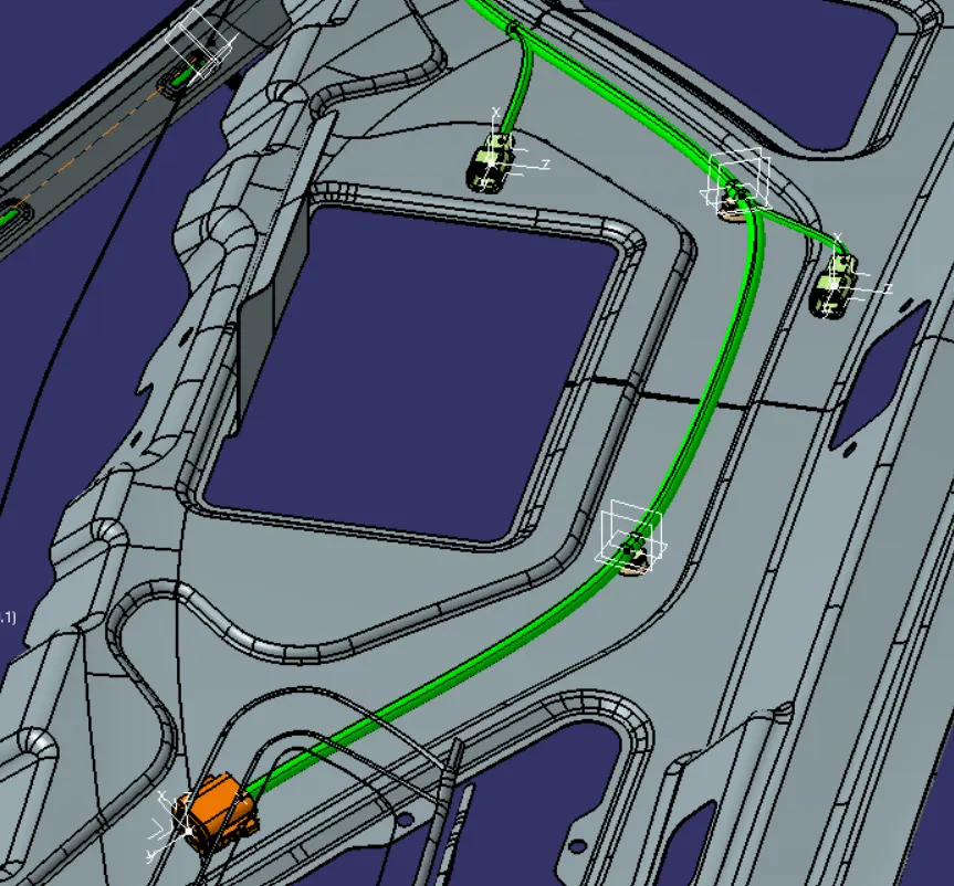
Before, bundle routing we have to make a hole through the upper side of the inner panel of the backdoor for the bundle passing from interconnection connector and also create a mid point in between for bundle support and its flexibility to avoid fouling of the harness.
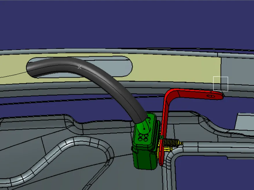
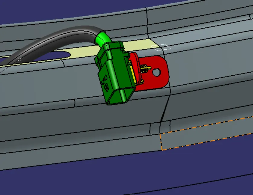
- Now, the car backdoor assembly is ready for the bundle routing as shown in below image.
- Also, we have activated harness assembly as geometrical bundle.
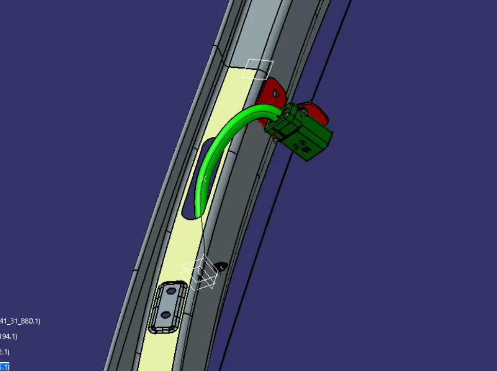
- Let, we have started bundle routing from interconnection connector and assumed diameter of main trunk is 12mm.
- The diameter of bundle leading to tail lights and number plate lights, boot opener is 8mm and 5mm respectively.
- The bend ratio is assumed to be 1.4 and appropriate slack between 1-10% is given wherever needed.
STEP 6 :-
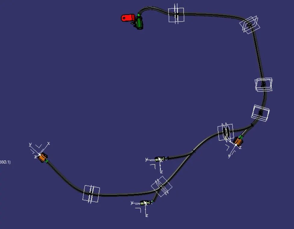
ADDING PROTECTIVE COVERINGS TO THE HARNESS BUNDLE :-
- After bundle routing, we have to add protective covering to the harness bundle so that it will get protected from the damage.
- Here, we have used COT-TUBES for the current harness assembly.
- We have given start and end extremity wherever needed for the COT-TUBES as shown in below image.
STEP 7 :-
CHECKING BUNDLE CONTINUITY :-
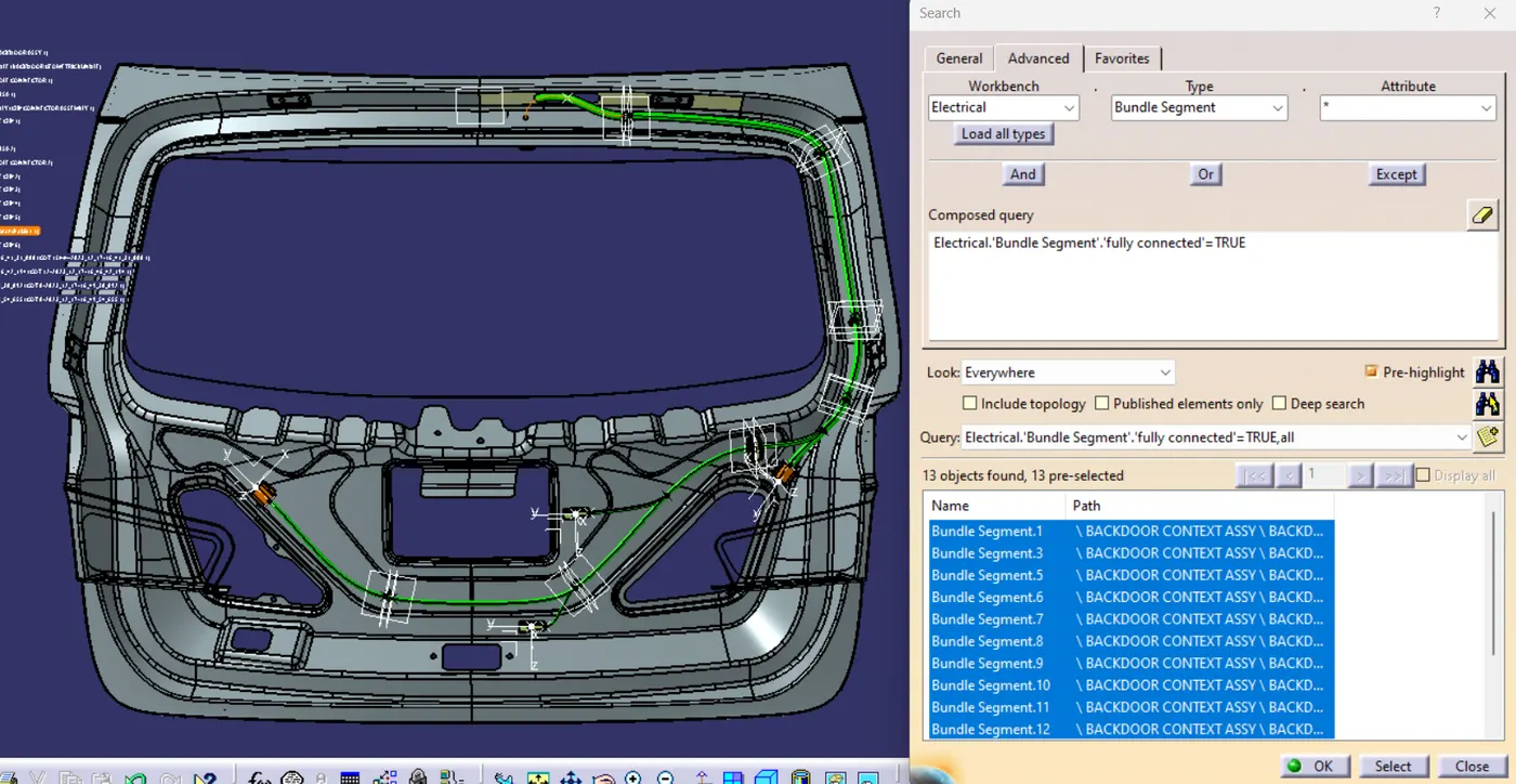
- First, we have to select multi-branchable and go through the sequence as Edit>Search>Advanced>Workbench-Electrical>Type-Bundle Segment>Attribute-Fully Connected.
- After selecting 'True' condition will show all the connected bundle segments while selecting 'False' condition will show all the non-connected bundle segments.
- Here, we have selected 'True' condition and search for the results. All the bundle segments are highlighted and showing that all the bundle segments are connected electrically as shown in below image.
STEP 8 :-
CREATE FLATTEN VIEW OF THE WIRING HARNESS BUNDLE :-
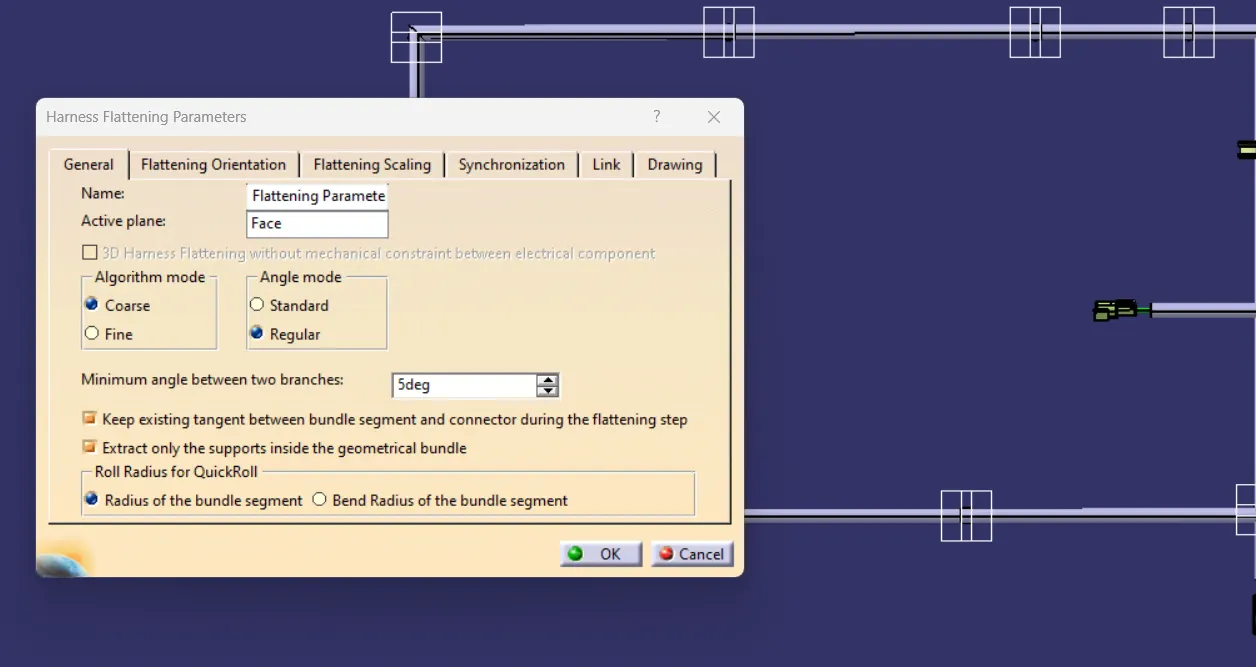
- To create a flatten view of the harness assembly, we have to work in Electrical Harness Flattening workbench in Catia V5.
- Also, we have to make sure that the flattening file is saved into the same folder where we have all the parts of the harness assembly.
- As shown in below image, while defining the wiring harness flattening parameters make sure to select Single line for bundle segment and Double line for protective covering.
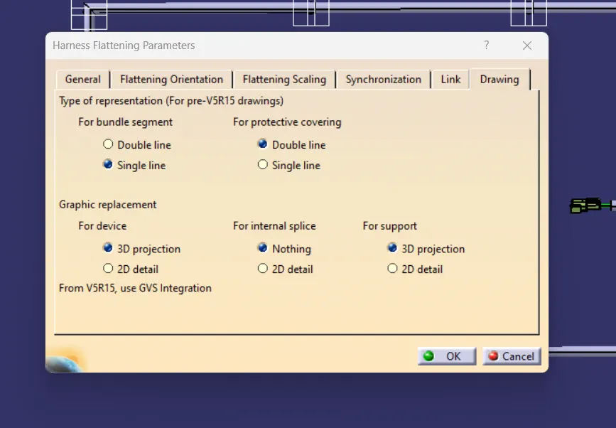
- After that, we have to extract and bring the bundle assembly into the car backdoor flattening product file.
- To flatten the harness assembly, we have selected Face as an active plane and selected all the branches.
- Now, we have a flatten view of the wiring harness geometrical bundle assembly.
- After creating flatten view, we have to rotate the connectors and clips in right direction along the selected plane using manipulation .
- We have designed the fatten view by using feature like rotate for better representation of the harness as shown in below image.
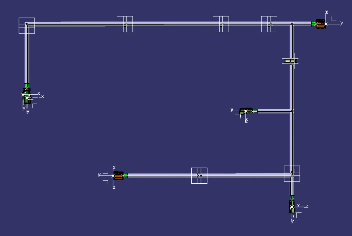
STEP 8 :-
CREATING FLATTEN VIEW DRAWING FOR THE WIRING HARNESS ASSEMBLY :-
- Now, we have to make new drawing file and define all the necessary drawing parameters.
- As shown in below image, we have to insert front view of the harness assembly into drawing file and define drawing properties.
- It should be noted that for the Dress-up feature 3D wireframe is always ON. If this setting is not selected then the bundle segments will not be visible on the drawing view.
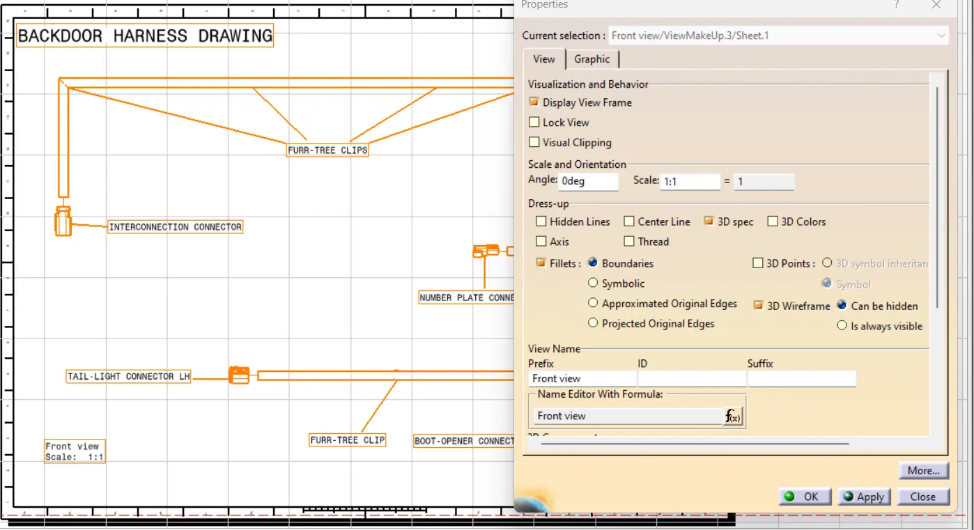
FINAL DRAWING OF THE FLATTEN VIEW FOR THE CAR BACKDOOR WIRING HARNESS ASSEMBLY WITH ALL OF ITS COMPONENTS :-
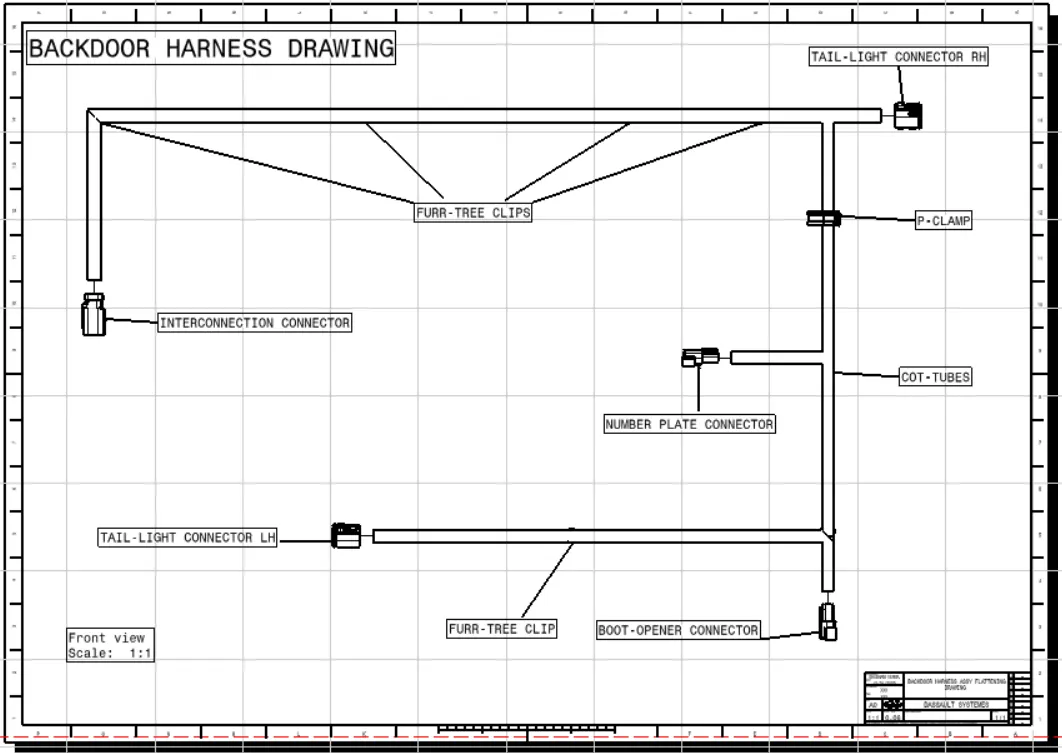
- 6} CONCLUSION :-
Routing of the wiring harness for the car backdoor assembly has done and prepared flatten-view drawing in Catia V5. Applied all the packaging rules while routing the wiring harness, implemented industry best practices in the harness design. Also, provided details like clearance, clipping selection, harness fixing requirements, harness continuity in order to design the harness.