Project 2
-
Designing Wiring Harness Route on Backdoor in CATIA V5
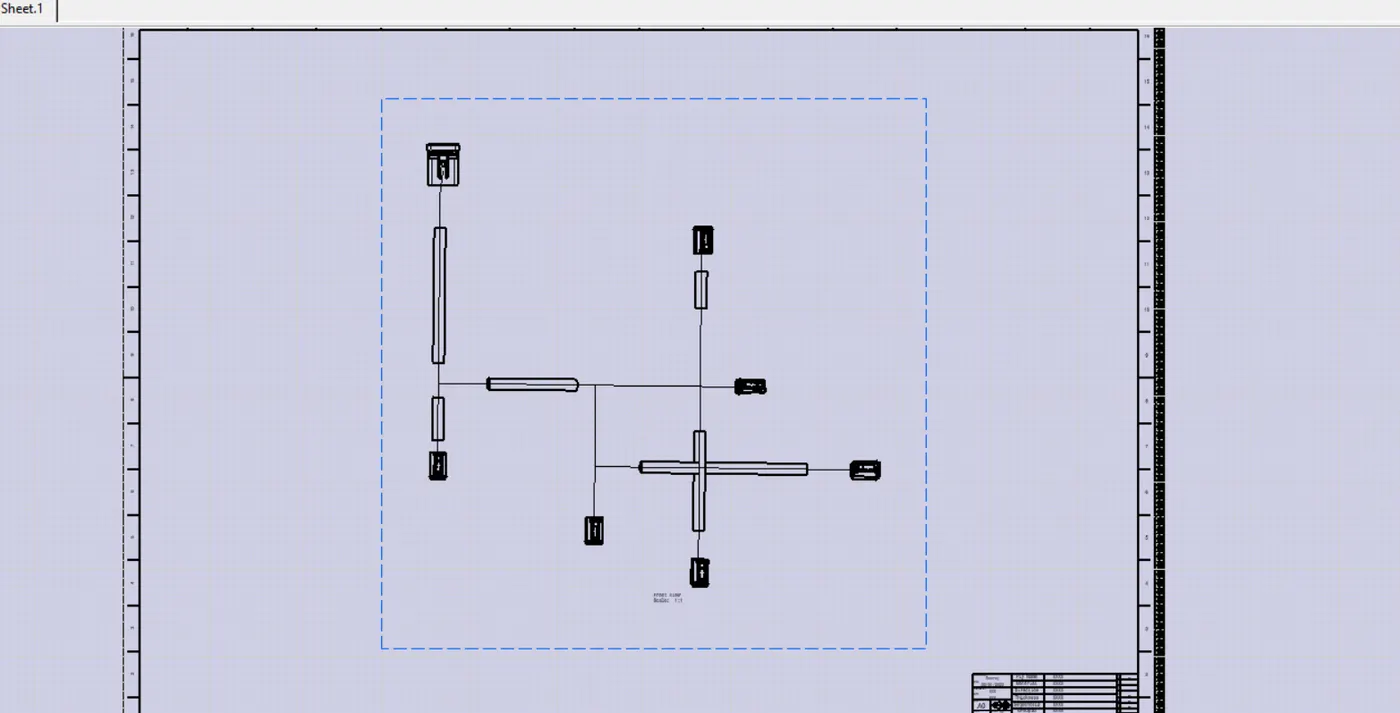
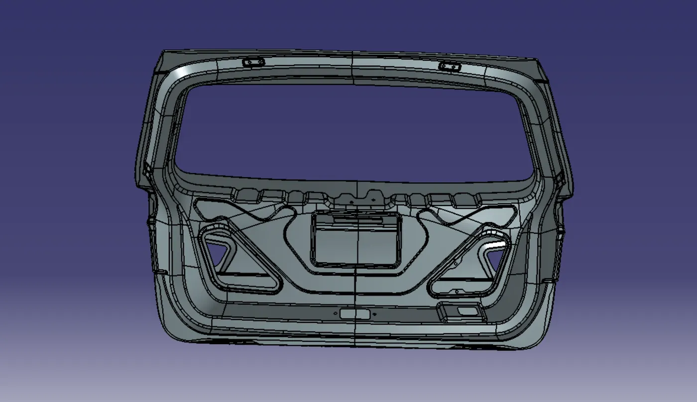
AIM: To design a route for the wiring harness on the given backdoor and prepare a flattened view drawing in CATIA V5.
Objective:
-
Analysis of Electrical Connections:
- Identify the electrical connection components required.
- Determine the number of connectors and mounting equipment needed.
-
Creating Context Assembly:
- Open a new product file in CATIA V5.
-
Importing Backdoor CAT File:
- Import the CAT file of the backdoor into the new product file.
- This will serve as the basis for routing the wiring harness.
Procedure:
-
Open New Product File:
- Open CATIA V5 and create a new product file.
-
Import Backdoor CAT File:
- Use the "Import" or "Insert" command to bring in the CAT file of the backdoor.
- This file will serve as the main component for the wiring harness routing.
-
Identify Electrical Components:
- Analyze the backdoor and identify the locations for the 6 connectors and mounting equipment.
-
Create Context Assembly:
- Assemble the backdoor CAT file into the new product file.
- This assembly will provide the context for routing the wiring harness.
Next Steps: The following steps would involve the actual routing of the wiring harness, creating a flattened view, and generating a drawing. This would include defining the path, selecting appropriate connectors, and ensuring adherence to design guidelines.
-
Defining Electrical Components in CATIA V5
Connector Connection Point:
-
Switch to Part Design:
- Open the backdoor part in the Part Design workbench.
-
Create Midpoint on Contact Face:
- Identify the contact face where the plug and connector mating surfaces will be connected.
- Create a midpoint on this face, ensuring it is normal to the wire bundle insertion.
-
Create Axis System:
- Still in Part Design, create an Axis System using the midpoint.
- Define the axis direction as needed for the connector connection point.
-
Switch to Electric Part Design:
- Now switch to the Electric Part Design workbench.
-
Define Part as Connector:
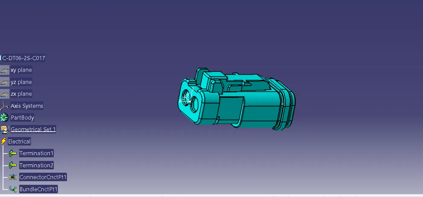
- Define the part as a connector in CATIA V5 by specifying the number of terminations required.
-
Define Connector Connection Point:
- Within the Electric Part Design workbench, define the connector connection point.
- This involves associating the created Axis System with the connector, specifying the position and direction.
Bundle Connection Point:
-
Switch to Part Design:
- Switch back to the Part Design workbench.
-
Create Midpoint on Contact Face:
- Create a midpoint on the same contact face identified earlier, ensuring it is normal to the wire bundle insertion.
-
Switch to Electric Part Design:
- Return to the Electric Part Design workbench.
-
Define Bundle Connection Point:
- Since the component is already defined as a connector, proceed to define the Bundle Connection Point.
- This step involves specifying the position and direction of the bundle segment connected to the connector or equipment.
By following these steps, you can effectively define the electrical components, including the connector connection point and bundle connection point, ensuring accurate positioning and alignment for the subsequent wiring harness routing on the backdoor.
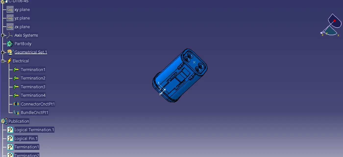
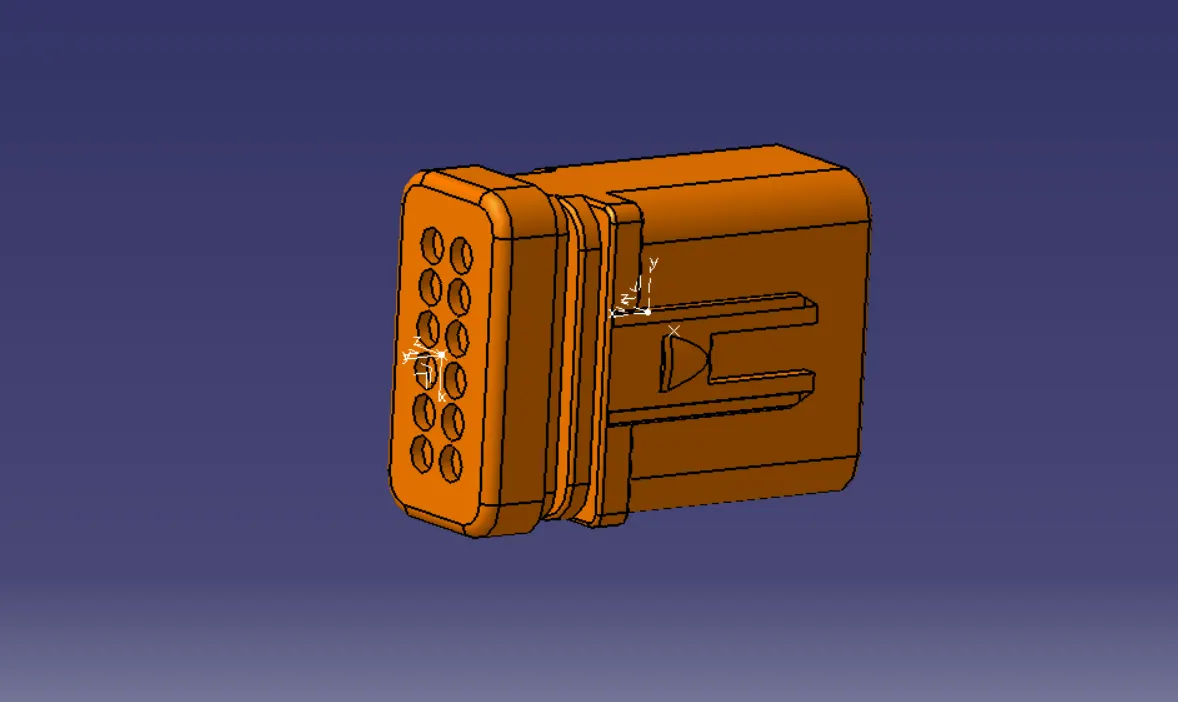
- C-1563689-1:
Defining the four-pole terminal connector electrically.
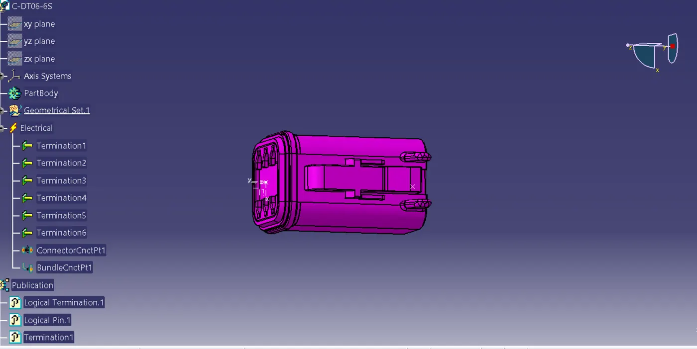
3. Placement of Connector, Clamp, Channel, and Route of the Bundle:
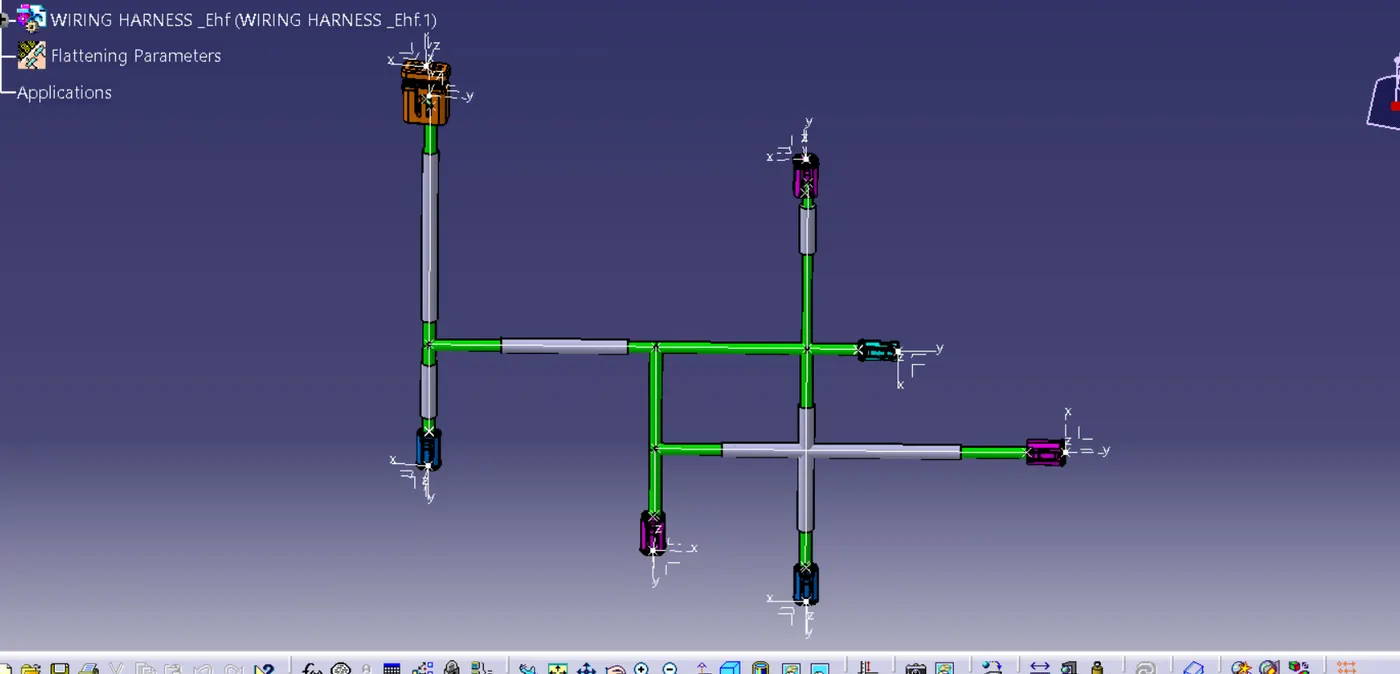
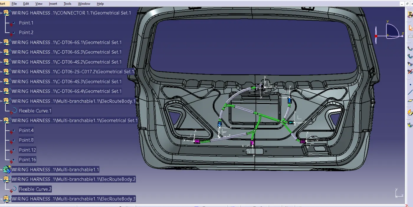
- After Defining the component as electrical, let's place those electric components as per the location provided in the backdoor.
- To place those components we can use,
- Manipulation tool
- Snap Tool
- Smart Move Tool
- Compass
- others Tool
- Now after placing the electric component at the location.
- Let's Start Bundle Routing.
- After Routing the bundle, provide the Cot-Tubes over the Bundle.
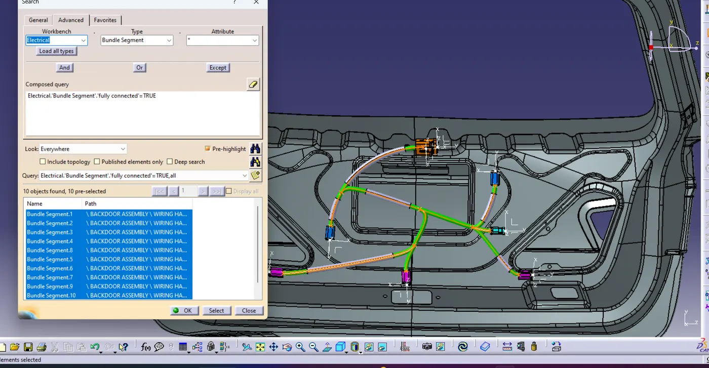
4. Checking the bundle Continuity. Adding the snap of results in the submission:
- Go to edit menu
- Select the Search option and in that select the advance option
- set the following option
- electrical
- bundle segment
- fully connected
- provide condition (true/false)
- After providing a constraint select the highlight option.
5. Flattening and 2-D drawing:
- After completing Routing and providing the Cot tube to it.
- Let's flatten the bundle.
- STEPS FOR FLATTENING THE ASSEMBLY:
- open the existing assembly which should be flattened.
- After opening the file create the new product file.
- Rename it first and save the file in the exact location where the existing assembly was saved.
- Switch to electrical flattening assembly.
- Set the flattening parameters.
- After setting the parameters, select the extract tool to extract the existing assembly.
- Once it's extracted, go to flatten tools.
- select the plane in which respect we have to flatten the assembly.
- With the Rotate tool's help, arrange the assembly representation.
- Hence the assembly gets flattened.
- CREATING 2D DRAWING:
- After flattening the assembly, create a new drawing.
- select the front view tool and select the view from the flattening assembly
- As there might be some mismatched will be there.
- Check the parameters of the flattening workbench,
2. right click on the 2d drawing and enable the 3d wireframe and make it always visible.
- After applying the setting, we got our desired drawing on the sheet.