Project 2
AIM
To Route the Wiring harness on Given car body and Prepare flatten view drawing in CATIA V5. Application of all Packaging rules, Industry best practices studied in this course shall be demonstrated in design. Apply Protection coverings as required.
ELECTRICAL DISTRIBUTION SYSYTEM
Electrical Distribution System deals with the physical and logical Architectures,Schematic development,Power Distribution,wiring harness design,wiring harness componenet design of given electrical system.
E&E ARCHITECTURE
E&E Architecture is high level connectivity diagram represent the number of system,subsystem and logical connectivity between them.It is also extended to show the Control Area Network (CAN) between different Electronic Controllers.
LOGICAL SCHEMATICS
It is a detailed design of E&E Architecture which is extended to show the logical connectivity between the different components and controls of the given system,subsystem.
ELECTRICAL SHCHEMATICS
Electrical S chematics is a detailed design of logical schematics which describes the pin to pin connectivity,Properties,Fusing Distribution,Grounding Distribution,Inter connects, wire properties,Circuit properties,Specification of component etc.., This is the end result of Electrical core design of system and used as an primary input for harness design.
WIRING HARNESS TOPOLOGY
Wiring Harness Topology is Strategy to divide or split the harness between different pieces to achieve the best manufacturability,Serviceability, Cost Effective design.
WIRING HARNESS ROUTING
Wiring Harness Routing deals wioth desired path of wiring harness into given vehicle environment by applying set of design roles and industry best practices.
WIRING HARNESS PACKAGING
Wiring harness packaging deals with fixing of wiring harness routing to ensure the safe,Reliable,and Durability of wiring harness by applying set of design rules and industry best practices.
WIRING HARNESS INTRODUCTION
It refers to the Assembly of
- Wires
- Connectors
- Terminals
- Protection Covering
- Insulation
- Clip & Clamping
- Fuse & Relay Box
- Retension Devices Guiding Channels Electronic Components
DESIGN FLOW OF EDS SYSYTEM
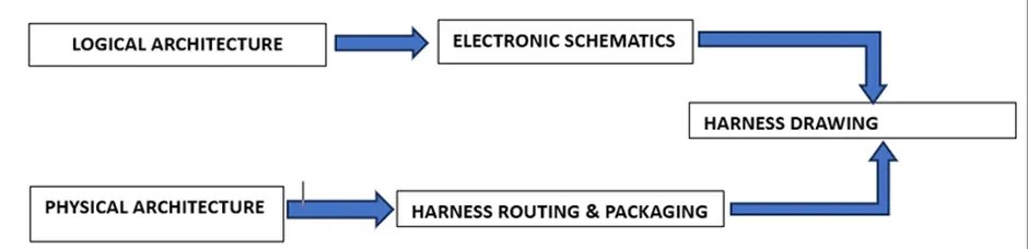
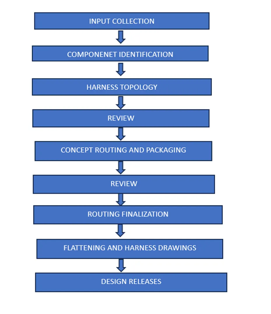
CONNECTOR
Connector is an electro mechanical device used to join the electrical circuits. Electrical connectors consists of Housing,Terminals,wedge,Locks,Seals,Cavity,Mounting Cam etc..,
PROCEDURE
- Download the File and Save the folder as cad part
- Create Catalog
- Catalog creation
File -> New -> Catalogue document -> Add Family -> Save
WORKING PROCEDURE
- Create Product name it as Wiring harness assembly
- Create new product name it as geometrical bundle
- Open Mechanical Assembly design workbench
- Download connectors
- Create Electrical design with Bundle connection point and connectoe connection point
- Copy And Paste the respective connectors in Geometrical bundle product
- Use Manipulation command and move to respective place
- After that click Geometrical bundle workbench .it changes electrical part
- Open Wiring harness assembly
- click multiple branch document
- create routing diameter 10mm from connector
- After that ADD BRANCH Point in required area for branches
- Again click Multible branch document
- create a sub branches in Connectors
- Click Protective covering and select the catalogue for cot tubes 15mm
- Start extrimity point and end extrimity point 30mm
- Click Protective covering and select the catalogue for cot tubes 10mm
- Start extrimity point and end extrimity point 30mm for connectors
- Click Harness Flattening workbench and Click the Flattening command
- Select the bundle and click all
- Next click the scale option and give the respective dimensions
- Finally Creating a Drawing
BUNDLE CONNECTIVITY STATUS
- Open the Mechanical Assembly workbench
- Go to Edit option click Search
- Click Advanced and select the Electrical and Bundle segment
- Click fully connected
SAVE AS CAT.PART
- Open the Mechanical Assembly workbench
- Open Tool option and Click the Generate CAT PART From product
- Select the Assembly click ok
- Save as IGS file.
HARNESS FLATTENING
- Click flattening parameters
- go to general settings
- pick the algorithm mode coarse and angle mode regular and angle 20 degree
- Tich the exact ,keep exist and radius of bundle
- Next go to drawing option
- click bundle segment single line and protective covering double line
PROCEDURE
- Open the Harness Assembly Flattening workbench
- click the Extract option and Go to the assembly and click the product
- Click the Flatten option and select all branches
- Rotate the respective place
- Click scale option and Dimension to be taken as per drawing
DRAWING CREATION
- Click the File and create new Drawing file
- Click front view and click the datum or face
- Go to properties click view
- tick thre fillets,boundaries,display view frame and 3d spec
- Tick the 3d wire frame and always visible and click ok
- Select the Ballon options and click the connectors
- Open the Edit option Select Background sheet
- Click the title box
- Click the Bill Of Material option
- Save the Drawing
RESULT
Thus, the Route the Wiring harness on Given Engine and Prepare flattened view drawing in CATIA V5. Application of all Packaging rules, Industry best practices studied in this course shall be demonstrated in design. Apply Protection coverings as required to be Completed.