Project 2
PROJECT 2
Purpose-
1)Initiate a concept of Fixture design.
2) Perform 3D finish on the Assembly design
3) Perform 2D finish with output documentation
4) Write a Detailed Report describing the process (what changes are made to the design) and attach relevant images.
Answer -
1) Fixture concept design-
A fixture is a work-holding or support device used in the manufacturing industry. Fixtures are used to securely locate (position in a specific location or orientation) and support the work, ensuring that all parts produced using the fixture will maintain conformity and interchangeability. Using a fixture improves the economy of production by allowing smooth operation and quick transition from position to part.
The following part is given for the fixture design, which includes 5 parts shown in different colors as well.
Following5 data is required to design the BIW fixture.
'- First to understand the scope of the work. This means what is expected by the customer. Every customer has its specific requirements and it may have its own raw material, electric, pneumatic, cad, and design standards. Every customer also gives different inputs and expects output e.g. 2d drawing, process sheet in xls, pdf, CAD format of design, layout format, and OLP.
A functional requirement is a basic requirement that defines the function of the fixture whether it is being used for welding, Hemming, Checking fixtures, or storage racks. Depending on this the design considerations are going to change while designing the fixture.
Bill of material (BOM) of the components to be welded- spot welding
CAD panel data or at least a 2D drawing of assembly and individual panel data
Sheet metal panel thickness.Plays a major role to decide on 2 metal or 3 metal welds.
Spot Detail information like the total no of spots and spacing between the spots.
Weld information clarity from drawing like 2-metal or 3-metal welding
PLP (Principle location scheme) of the individual panel and total assembly.
Cycle time - is calculated or can be found out as per manual or robotic welding process.
Process sheet if Process engineering is done - where loading sequence, no of clamp data, and gun data are mentioned.
All clamping cylinder and fixtures standards.
CAD -Software Guidelines
Raw material standards
Design guidelines
Bought out item(Purchased parts) standards like pneumatic items, toggle clamp, bearing, screw, dowel, etc company information
The fixture will be the spot welding fixture where a robotic gun will be used for spot welding hence the institution should have ample space that the spot gun should come in to do its work should go out without striking any of the parts of the fixture. The green spots shown in the image are the spot weld where the spot welding will be done by the welding gun. So we have to place the fixture parts by considering the spot weld & also by doing the gun study we have to check the fouling of parts with the gun.
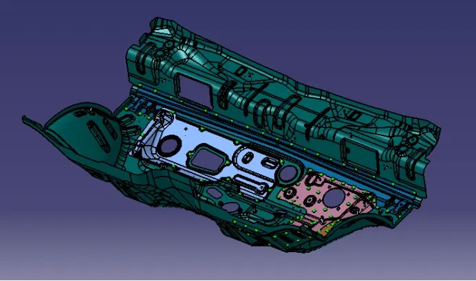
By considering5 all above-mentioned requirements following fixture design concepts are prepared.
'- For designing any fixture 3-2-1 principle is the most important thing to be considered. Here also 3-2-1 principle is taken into consideration while designing. Different units are used to fulfill the requirement of constraining the DOF of different parts like Fix pin units, retractable pin units, Power clamp units, Rest units, etc.
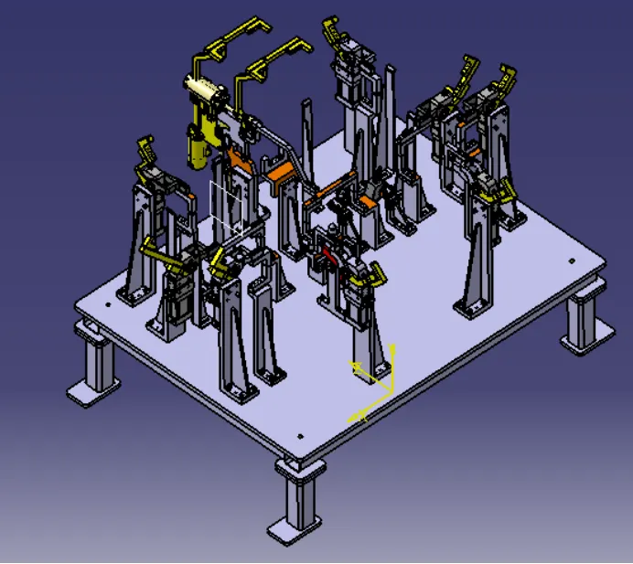
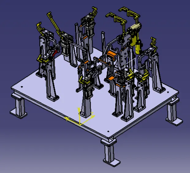
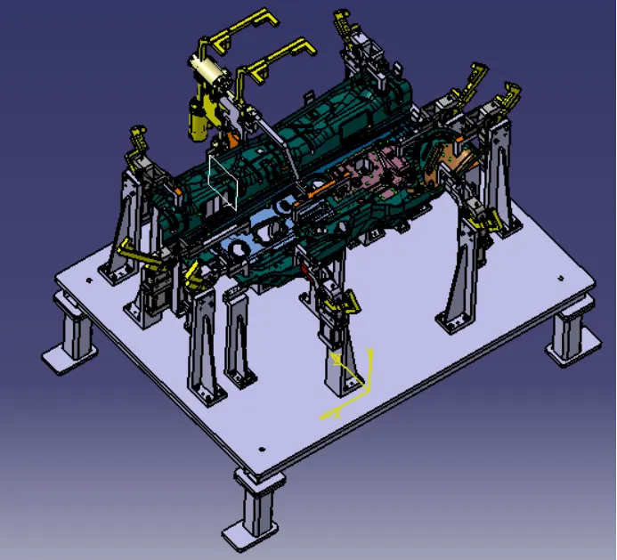
Fig shows the entire fixture with the panel & without the panel
As per the 3-2-1 principle of fixture we have to constraint degrees of freedom of the part so at the time of operation there will be fewer chances of distortion. For this purpose fix pin units & Retractable pin units are designed.
Fix pin units have 2-way shimming adjustment & Retractable pin units have 3-way shimming adjustment.
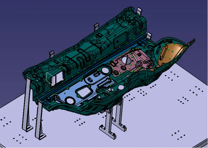
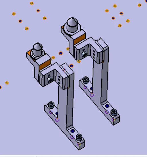
Fig shows the position of fix pin units Fig shows the designed fix pin units
Fig shows the position of the retractable pin unit Fig shows the Retractable pin unit
The power clamp unit is the unit designed to hold the car panel in position to do some process over the part. It includes NC block/ Rest/ Mylar by using a pneumatic clamp cylinder. The power clamping devices are utilized for positioning and holding products securely. It applies pressure on the product to hold it in the specified position. The holding should be firm enough to hold the part in its position & also it should not damage the part as well.
A clamp cylinder is a pneumatic device that works with pressurized air. The clamp cylinder is used to open & close the parts fixed to the clamp arm fixed to the clamp body.
Clamp cylinders are bought part.
They are in general 40, 50, 63 & 80 bore capacity.
Opens up to 135 degrees for horizontal clamp mounting.
Opens up to 105 degrees for vertical clamp mounting.
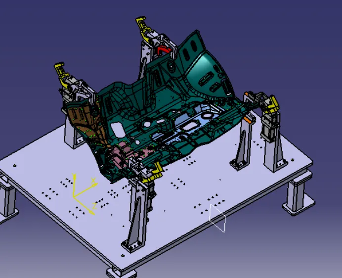
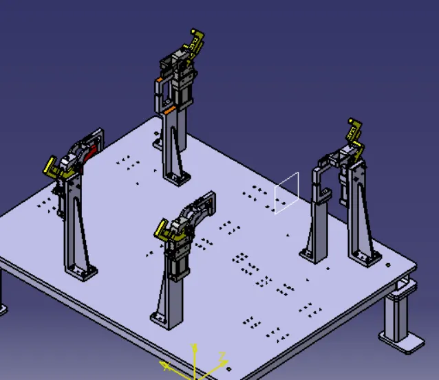
Fig shows the Power clamp desined to hold the part & its position with panel Fig shows the Power clamp desined & its position
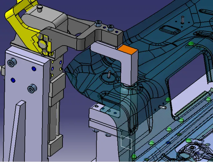
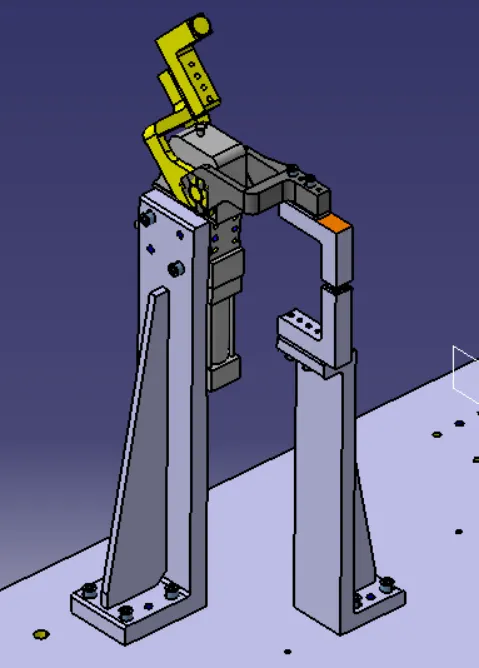
Fig shows the closer look of Power clamp unit desined to hold the part with its rest unit Fig shows the Power clamp desined & its Rest unit
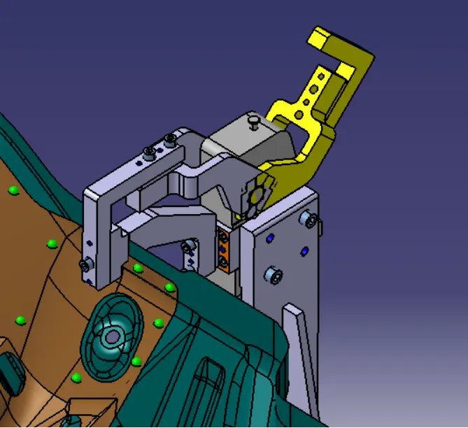
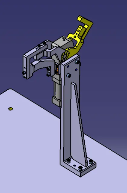
Fig shows the closer look of Power clamp unit desined to hold the part Fig shows the Power clamp desined
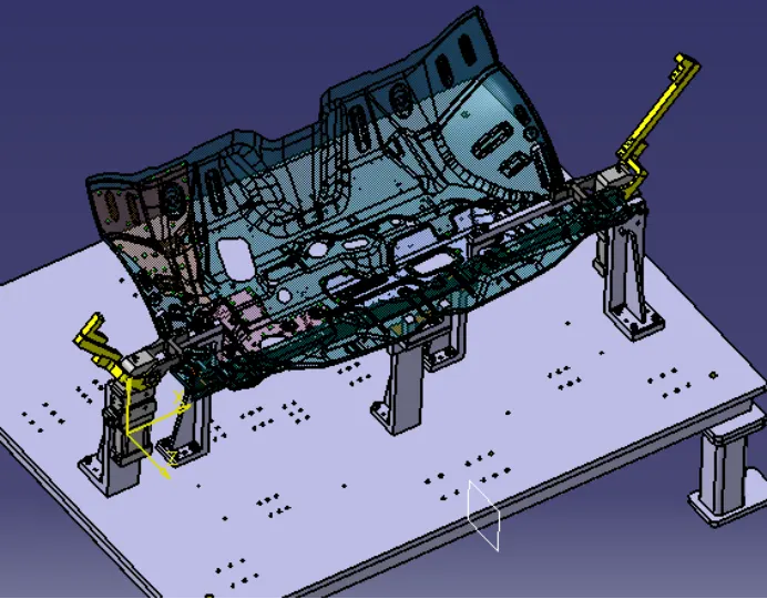
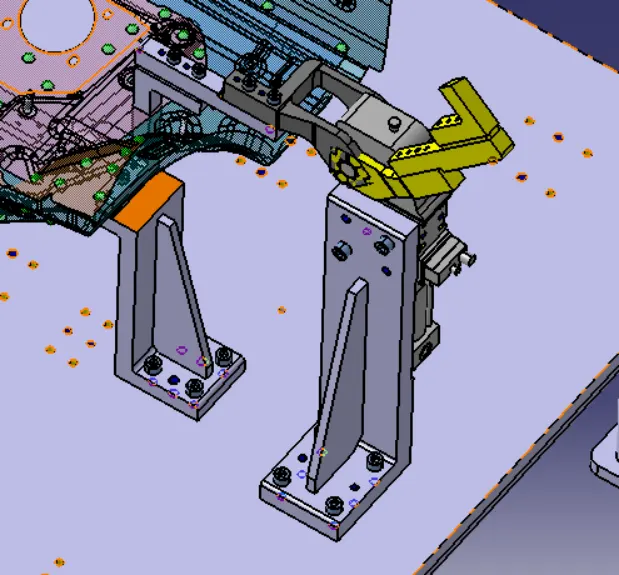
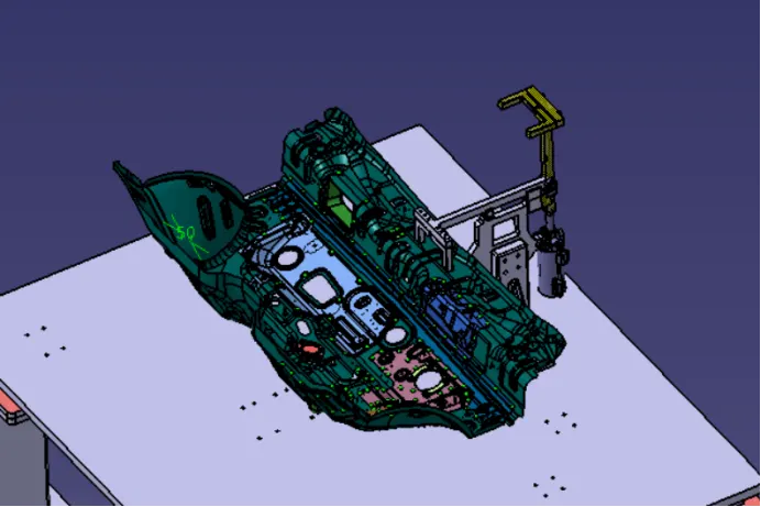
Fig shows the Power clamp desined to hold the part & its position with panel Fig shows the Power clamp & its rest unit
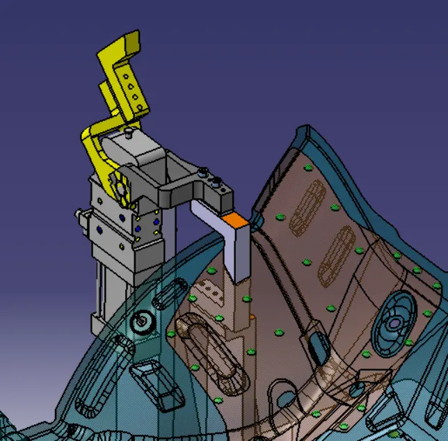
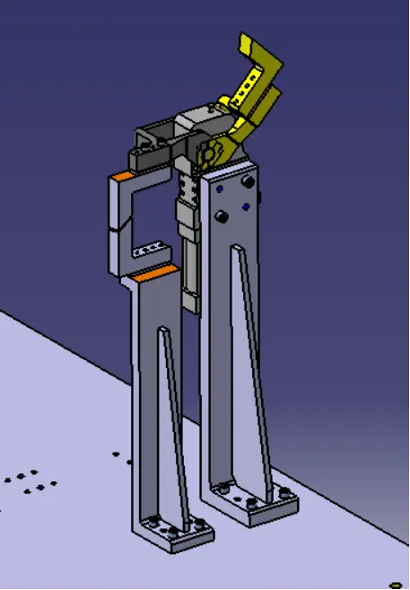
Fig shows the Power clamp desined to hold the part & its position with panel Fig shows the Power clamp & its rest unit
2) 3D Finish -
- 3D finish is the process where design is being completely finish & to be ready for final simulation & 2D detailing
- Following points are taken into consideration while finishing the design.
Hole concentricity & hole sizes- All parts Hole concentricity is checked & confirmed while finishing the parts.
Machining Area- The machining area in every part is defined & the machining area is highlighted by using orange color.
Nominality- All units dimensions are maintained nominal to facilitate easy assembly of the unit.
Holes colouring standard- Color Code standard used in the 3D finishing
Cyan - Simple Hole
Yellow - Threaded Hole
Orange - Machined area
Blue - Dowel pin Hole
Fasteners implementation- Fasteners are implimented in all unit as per the requirement & load on the part.
Avoiding clash between different part- Proper gap is maintained between parts to avoid the clash.
Mylar splitting as per panel profile- Mylar splitting are confirmed while finishing the design.
Proper renaming of parts/assemblies as per standard-proper renaming of parts & assemblies are done while finishing the design hence we can identify each & every part easily with unique identification.
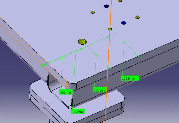
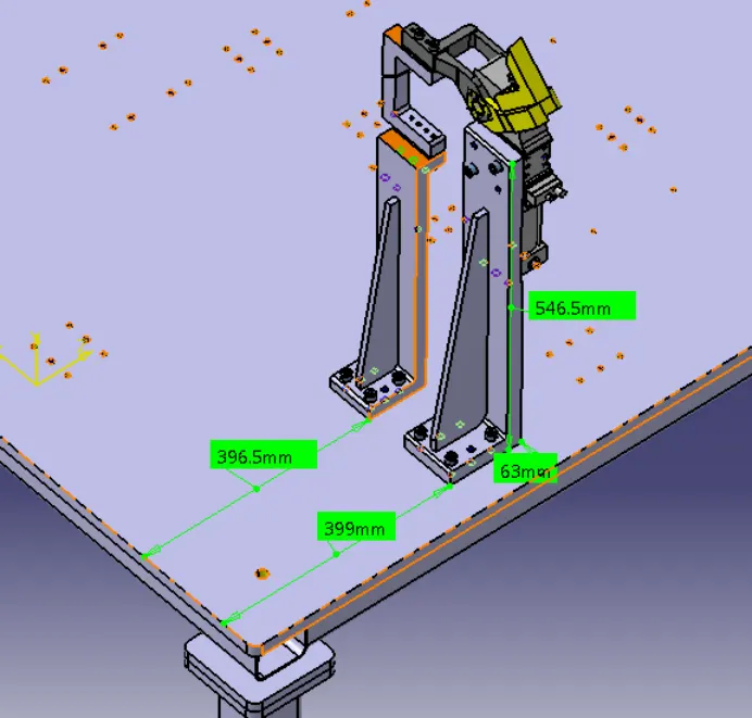
Fig Shows the nominality considered while 3D finishing of the part
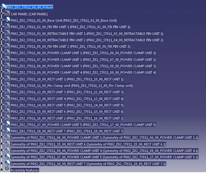
Fig shows the Design tree which having unique name for every unit & Child part to avoid confusion
3) 2D Detailing-
- A 2D drawing view consists of two-dimensional elements. A 2D drawing view allows you to quickly create or modify a drawing view without making changes to a part or assembly document.
- In fixture datailing Key sheet detailing of every unit is done which gives the idea placing of unit in assembly.
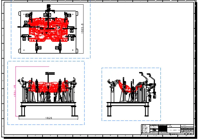
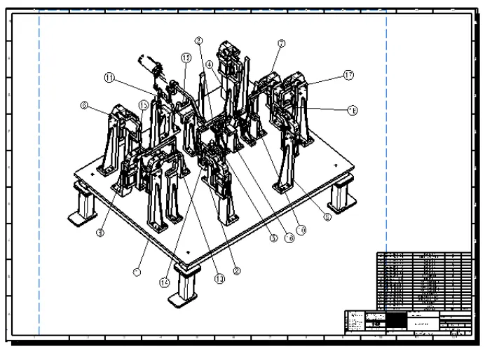
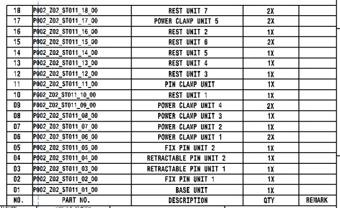
Fig shows the list of units