Project 2
Automotive Wiring Harness
Project 2
Aim
Route the Wiring harness on Given car body and Prepare flatten view drawing in CATIA V5. Application of all Packaging rules, Industry best practices studied in this course shall be demonstrated in design. Apply Protection coverings as required.
Available connector 3D data can be used, or you can download the connectors from www.te.com
Prepare & Submit all necessary reports like clearance, Clipping/Clamping selection, Harness fixing requirements, Harness continuity, Assumptions if any along with CATIA 3D data.
Context
- Surrounding data inspection
- Check the female connector
- Select male connector
- Placement of connectors
- Support equipment’s
- Placement of support equipment’s
- Harness installation
- Flattening
- Drawing
Surrounding Data inspection
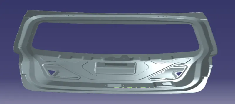
Back Door Panel
- The surrounding data is given
- First we need to check how many connectors are to be connected
- And following we can check where we can place the supporting equipment’s
- So for this Back door panel we can easily route since it is free from dust and water ingress
Check the female connector
- Now we need to check the female connectors which is provided in the given project
- Since there is no female connectors given we can assume four different connectors
- We can assume them as a dummy connectors
Selection of male connector
- Select the male connectors which will be a match of the female connectos
- Since we don’t have any female connectors we can use dummy connectors
- I have selected four different connectors which are mentioned below
- The selection of connectors is done from the te.com
- C-173090
- C-282080
- C-1563689
- The connectors are now electrically defined which is mentioned in detail below.
C-173090
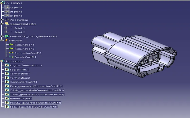
- The connector is Electrical defined by using the Electrical part design workbench
- Two different points are created which is for the bundle connection point
- And other one for the connector connection point
- Axis system is created so that the connector is connected to the female connector
C-282080
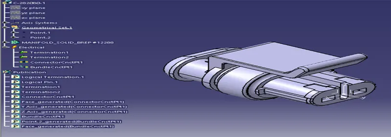
- The connector is Electrical defined by using the Electrical part design workbench
- Two different points are created which is for the bundle connection point
- And other one for the connector connection point
- Axis system is created so that the connector is connected to the female connector
C-1563689
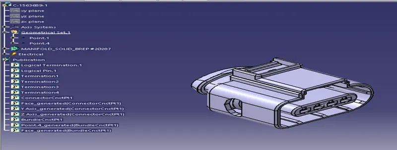
- The connector is Electrical defined by using the Electrical part design workbench
- Two different points are created which is for the bundle connection point
- And other one for the connector connection point
- Axis system is created so that the connector is connected to the female connector
Selection of Support Equipment
- The support equipment is very much required which is used to guide the harness
- As we can see that the given material is made of plastic we can easily have the drills in it
- We can request the manufactureing team to have the drills for the following support which is mentioned below
- P- Clamp
- Furr Clip
P-Clamp
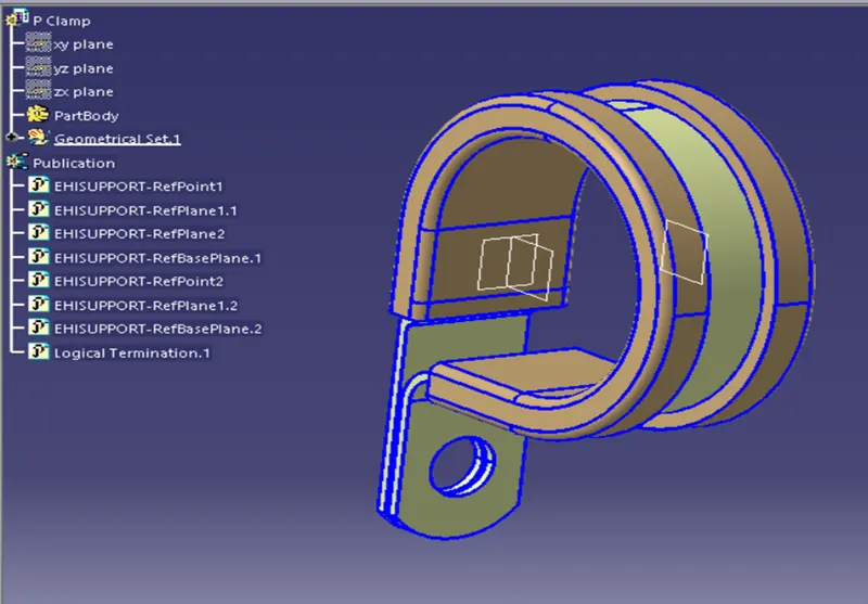
- The connector is Electrical defined by using the Electrical part design workbench
- Two different points are created which is for the bundle connection point
- And other one for the is also bundle connection point
Furr Clip
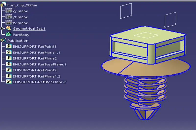
- The connector is Electrical defined by using the Electrical part design workbench
- Two different points are created which is for the bundle connection point
- And other one for the is also bundle connection point
Placement of Connectors and Support equipment
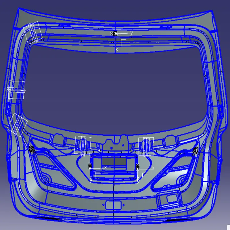
- The placement is planned as per the connectors which are provide by the Door panel team
- The placement should be clear that it should not harm the other systems
Harness Installation
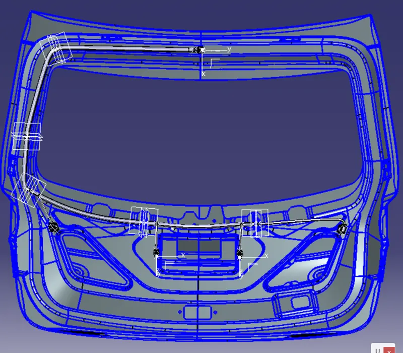
- Now we need to start the harness
- First we need to start from the interconnector
- And the connection are done which is given below
Checking of Bundle continuity
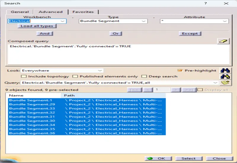
- This bundle continuity is required to be done by which we can know whether the connection are are going to all the connectors are not
- We can see that the all the bundles are fully connected and we are ready to the harness flattening
Harness Flattening
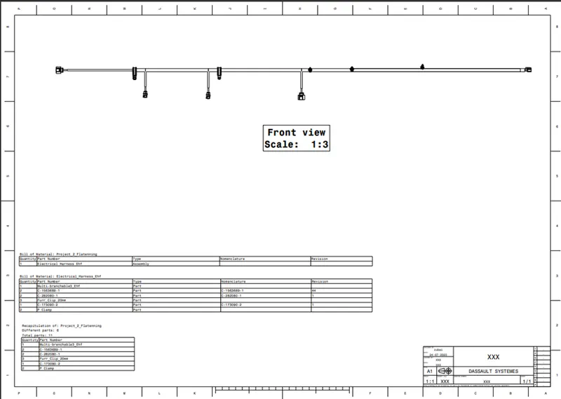
- The flattening is done which is required to modelling of the 2d drawing
- The flattened is done by which we can procide with the drawing
Drafting