Project 2
WIRING HARNESS ROUTING OF BACKDOOR USING CATIA V5
OBJECTIVE:
The objectives of this challenge are as given below,
- To Define the mechanical components electrically and prepare a catalogue for the same.
- To Provide proper routing of bundle without any interference and also provide support parts like clips and clamps.
- To Prepare a report with all the required images required for the challenge.
- To Attach all the file required for the challennge.
DESIGN METHODOLOGY
The design methodology or design approach which is used for this challenge is explained or given in the below flow chart,
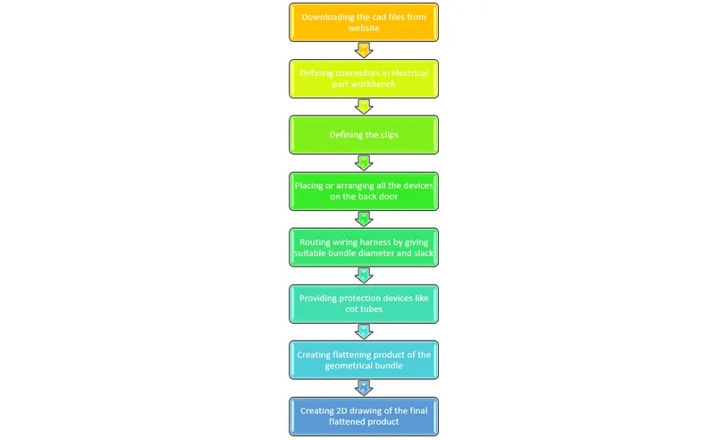
In this challenge, we will perform the Wiring Harness Routing of a Back Door Panel and at the end will prepare a flattened view drawing for the same. All packaging rules & the best industry practices will be followed during this process.
The steps that need to be followed for executing this task are as follows:
- Identifying the electrical components in the model
- Defining the mechanical components electrically or Importing the data from the catalogue
- Setting up the assembly by placing the required connectors, clips, clamps, etc
- Proper routing of the bundle without any interference
- Preparation of flattening file & 2D drawing creation
The electrical components in this model are Tail Lights & Number Plate Lights. These lights require power or current to operate hence the wires or bundles that we are going to route today will help us understand the length & path of the wire & also the connectors, clips and other parts that are needed for this project.
For the lights, we are first going to define the mechanical components i.e, connectors, electrically.
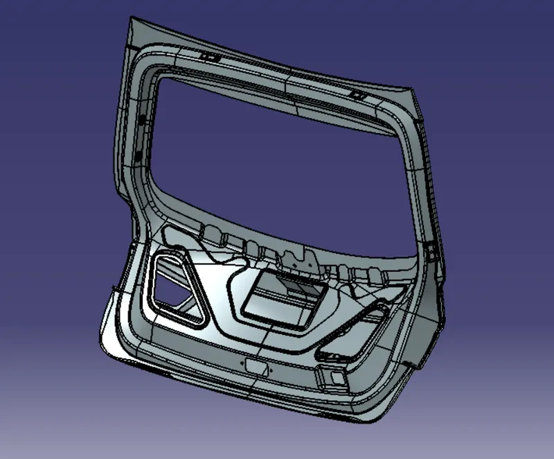
After which the support clips needed to be defined. These clips will help the bundle to be routed properly without any interference.
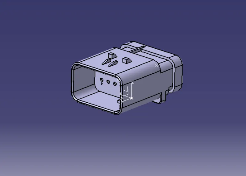
The bundle for this component needs to be connected to the vehicle harness system hence an interconnection connector will also be used in this project.
Once all the data is ready, we will create a context assembly under which 2 sub-assemblies are used, 1 sub-assembly will be the back door panel & another sub-assembly will hold the electrically defined components along with the bundle.
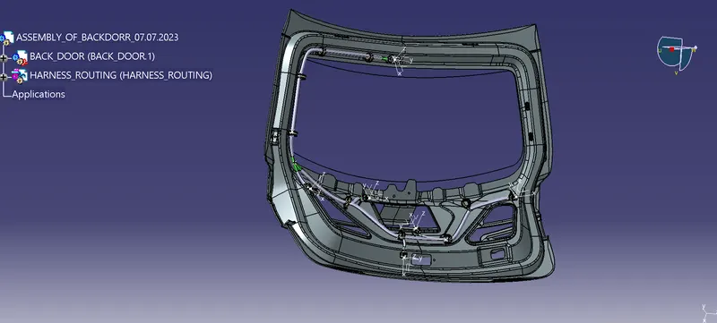
The Harness Engineer needs to decide the path for routing the bundle by considering all the environmental factors such that there will be no interference or difficulty faced during the execution in real-time conditions.
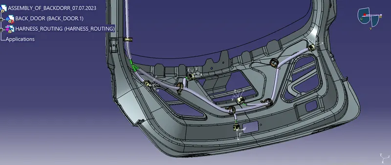
Now let us see the images of routing without backdoor,Since to minimize the effect of damage due to sharp edges and heat we have apply protective coverings on the harness bundles. The below images shows the wiring harness after applying protective devices,
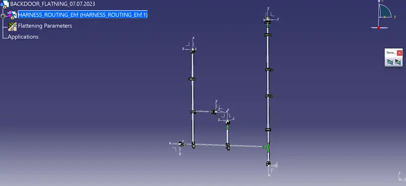
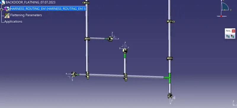
Now by using harness flattening assembly try to flatten the geomentric bundle and apply all the required operatiions such as bend, rotate to create the bundle in a manner that it will fit into the drawing sheet. The below image shows the final output of flattening product.
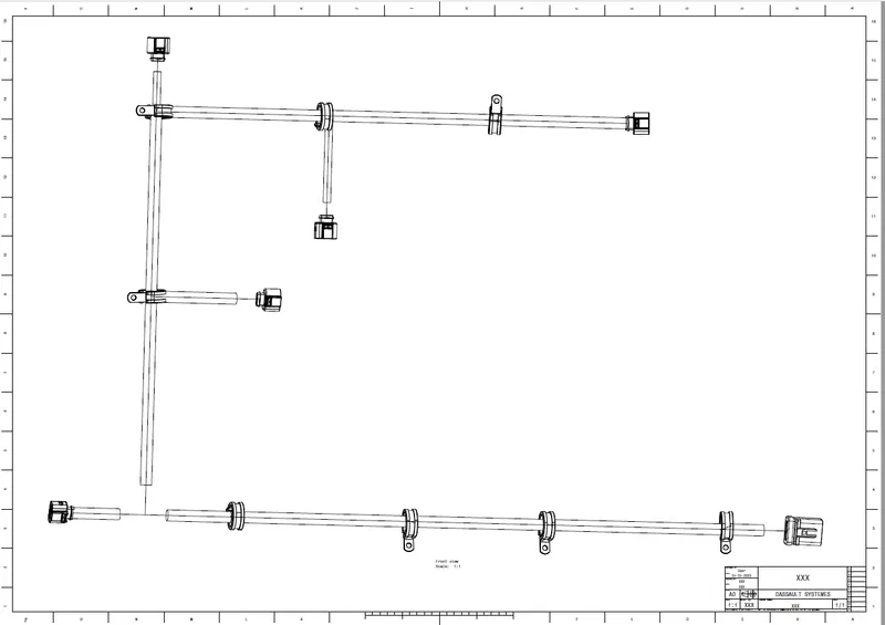
Now create a drawing file for the flattening product along with frame and title block & bill of materials and the image for the same is attached to here.
CONCLUSSION
Thus, the objectives of this challenge are achieved and a detailed report has been prepared. A zipped folder which contains the cad files is attached to the challenge successfully.