Project 2
AUTOMOTIVE WIRING HARNESS BACKDOOR
What is wire harness engineering?
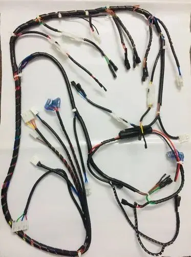
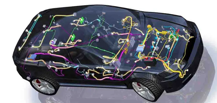
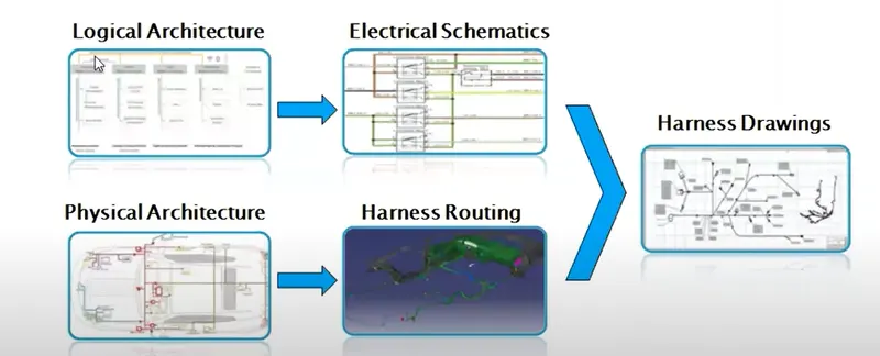
A wire harness is a system of insulated conducting wires bound together with insulating materials, used in the electrical system of a motor vehicle, complex machine or aircraft. Wire harness engineering is the development process of an electrical foundation for the safe and reliable distribution of power throughout a system. It forms the foundation of reliable, cost-effective and successful product design and manufacturing. The design, engineering and manufacture of wiring harnesses is complicated by shorter program launch cycles and increasing price pressure, coupled with increasing product and configuration complexity. Harness design software helps many companies address wire harness engineering challenges. Powerful design automation capabilities, coupled with model-based wiring harness engineering flow, help harness manufacturers cut costs, improve product quality and boost efficiency.
The Difference Between Wire Harness Assemblies and Cable Assemblies
One common assumption made about wire harness assemblies is that they are interchangeable with cable assemblies. Wire harness assemblies are often confused with cable assemblies because they both have similar features; however, they are not the same.
Wire Harness Assembly
As a short review, a wire harness assembly is a collection of bound cables and wires sheathed in a basic thermoplastic or thermoset material designed. The wire harness assembly sheath is simply designed to bring organization to the installation of cables and to provide basic protection from externalities. This basic construction defines wire harness assemblies as best suited for indoor use where externalities are minimal.
Cable Assembly
Similar to wire harness assemblies, cable assemblies consist of bound cables and wires. However, the material in which they are wrapped tends to be more durable. Cable assembly casings are usually made from materials, such as vinyl or thermoplastic rubber, that allow the unit to operate in the most intense environments where externalities abound. In comparison to wire harness assemblies, cable assemblies are often best suited for outdoor use or within environments operating under various amounts of stress, such as heat, moisture, and friction.
Statement of assignment :
Route the Wiring harness on Given car body and Prepare flatten view drawing in CATIA V5. Application of all Packaging rules, Industry best practices studied in this course shall be demonstrated in design. Apply Protection coverings as required.
Available connector 3D data can be used, or you can download the connectors from www.te.com
Prepare & Submit all necessary reports like clearance, Clipping/Clamping selection, Harness fixing requirements, Harness continuity, Assumptions if any along with CATIA 3D data.
Introduction-
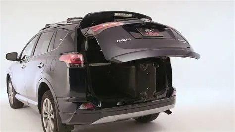
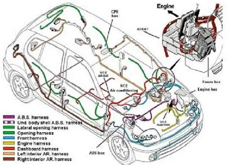
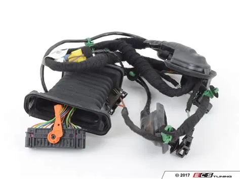
The trunk or boot of a car is the vehicle's main storage or cargo compartment it also have a hatch at the rear of the vehicle. It is also called a tailgate.These doors can be operated manually or electric powered. here we design the trunk or back door wire harness using the Catia.The Backdoor is an assembly of many parts such as inner panel, outer panel upper, outer panel lower and Reinforcement.Inner panel is attached to the outer panel using mastic sealant.
Types of doors based on working position
- Top Mounted Door
- Side mounted Door
- Bottom Door
Aim- To route the wiring harness on the given backdoor assembly and prepare the flatten view drawing in CATIA V5.
Objective-The objective of this project is to route the wiring harness and prepare flatten view drawing for the Backdoor of the car. All types of packaging rules have to be considered while routing the harness and industry based practices shall be demonstrated in harness design. All necessary details like clearance, clipping/clamping selection, harness fixing requirements, harness continuity should be provided in order to design the wiring harness.
METHODLOGY OF DESIGNING :-
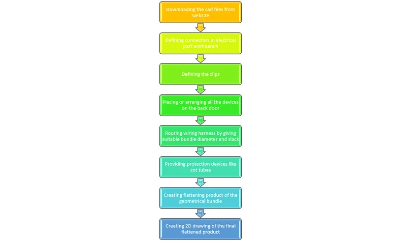
Assumpctions to be followed-
- Wiring harness should be routed in such way that it is easy to assemble and access.
- Easy manufacturing, installation, removal and maintenance have to be considered while designing the wire harness.
- Wiring Harness should be kept away from sharp environment like edges, corners etc.
- Avoid harness routing and clipping in the blind zones or hard to reach areas during harness assembly or service.
- Provide additional slack if needed according to the surrounding and harness bending requirement. If harness is passing through the closures/doors or tail gates then envelope dimensions during opening and closing of doors shall be considered to provide the slack. Check the harness slack requirements with open and close conditions to avoid excess slack.
- Routing through small structural holes and openings shall be avoided. To minimize chaffing and handling of the wiring harness during installation.
- It should be make sure that there is no case of fouling while designing the wiring harness in the CAD environment. Additional mounting equipments like clips/clamps may be used to avoid fouling.
- Use of rubber grommet is recommanded if harness is passing through sheet metal panels. Example- firewall, passing to door, tail gate etc.
- The branch length should be greater than 50mm.
- The minimum distance between the clip and branch point should be at least 25mm.
- The minimum distance between the two branch points should be at least 50mm.
- Clips/clamps used for the wiring harness should be easily available in the market to avoid extra cost for custom mounting solutions.
Steps required-
STEP 1 - Creating context assembly
Now Create the Electric wire harness context assembly and Geometric bundle as a subassembly containing all the electric parameters as shown below,
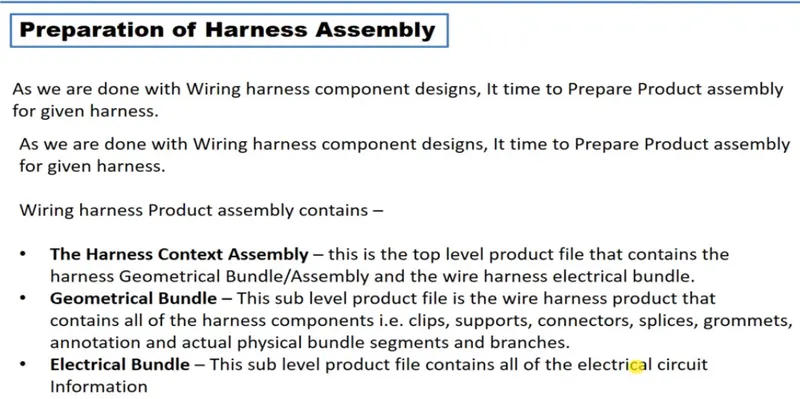
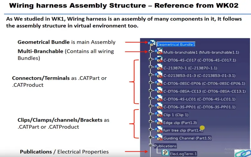
Add the all connectors which are electricaly defined to the Geomteric bundle assembly.
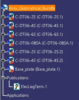
Then define this Geomteric bundle assembly as electricaly, for that we need to switch to Electric harness assembly workbench.

select Geometric Bundle then click on Geomteric bundle assembly (In specification Tree)
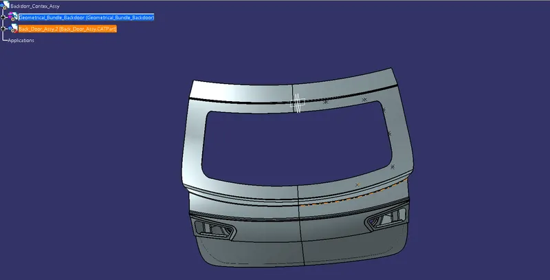
Now, to position all the connector as given in input file,
Create enviroment on which the bundle assembly will be placed.
Draw the sketch as given dimension in input just for referance purpose.
TEP 2 - Defining connectors electrically
Choosing right components for the wire harness routing.here we are using the components for backdoor upper and lower lights,wiper motor,sensors,and defogging equipment.the connectors used are first elecrically defined and then added to the catia model.
|
Connector definition. |
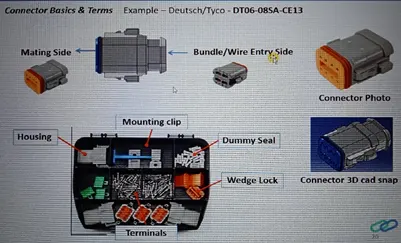
shows the Connector definition and the detailed process. Fig 16 shows the different connector parts.
 |
|
Connector parts. |
Geometry Parameters – Points and co-ordinate system (axis).
Connector connection points – This point is used for the connection of one connector to another connector.
Harness bundle entry point – This point defines where the harness bundle segment point will end when routed to the electrical connector.
Cavity connection point (optional): This point is used to define the connection of a connector to a connector clip. This only applies to connectors which have the mounting feature for a connector clip.
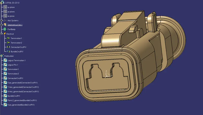
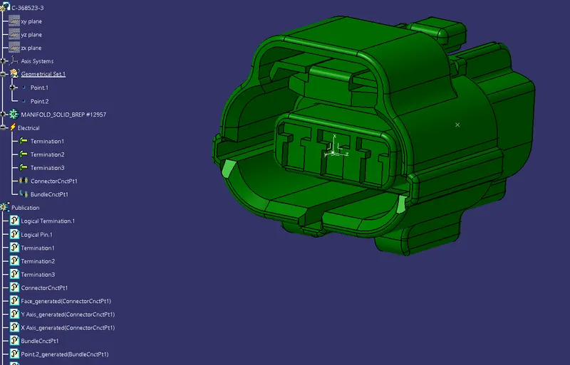
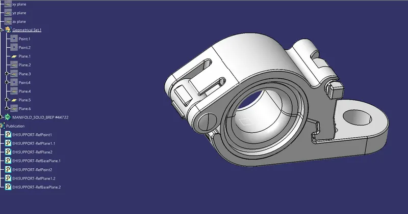
The type of connectors used are given below-
1- Interconnection connector
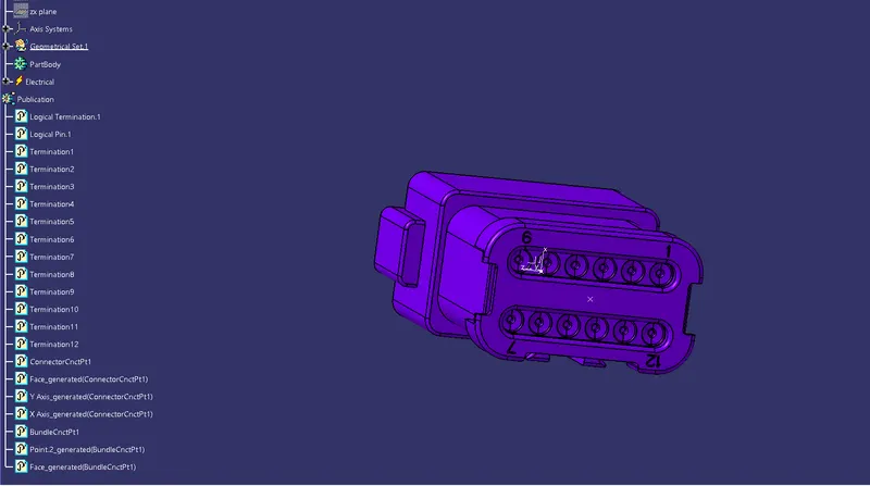
2- 2 pole connector used for light,sensors,motors.
3- 3 pole connector used for light,sensors,motors.
3- Clip and clamp is used to set the location of wire
STEP 3 - Adding connectors and needed equipments
Opening the equipments in catia and using the snap and smart move and positioning the connectores and supports.
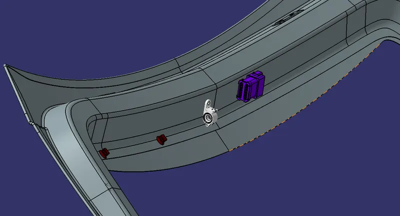
The first part we position here is the interconnection connectors.
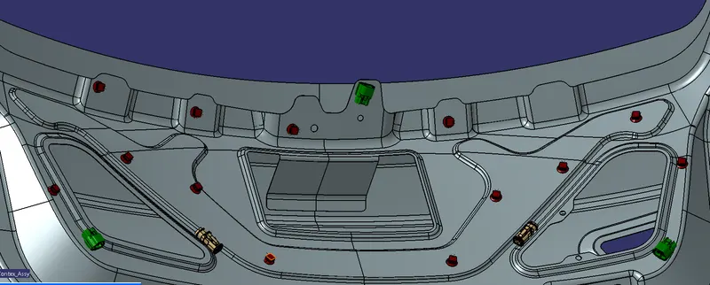
we place the Furr tree clips for the support in the needed positions.
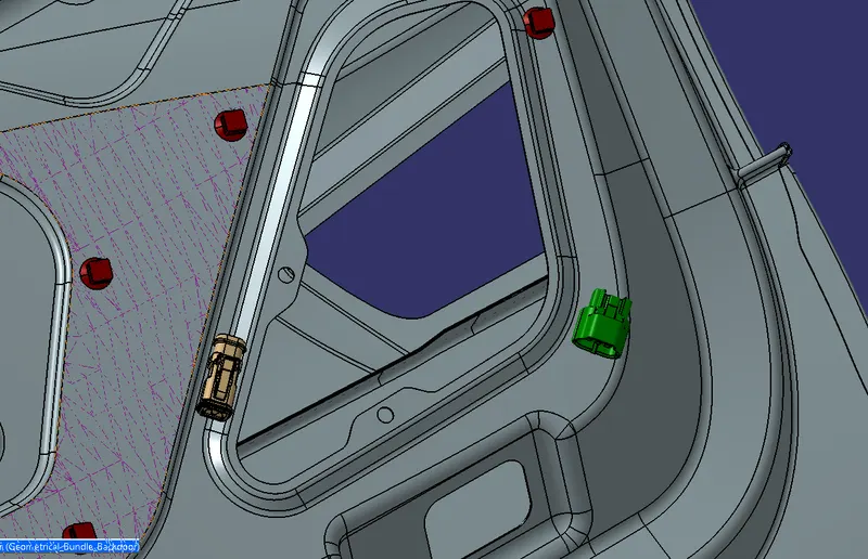
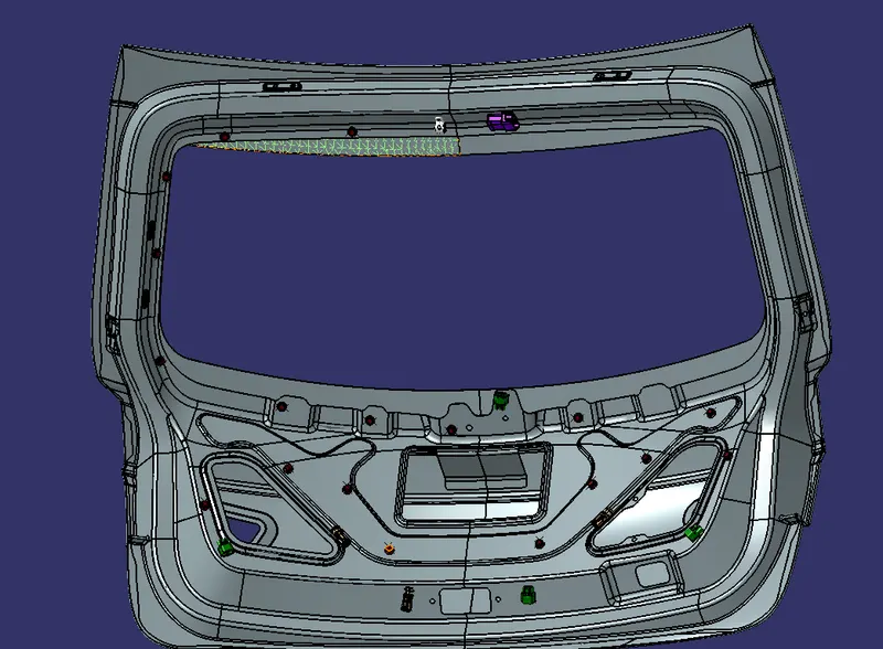
proper connectors are positiioned for different electrical equipments
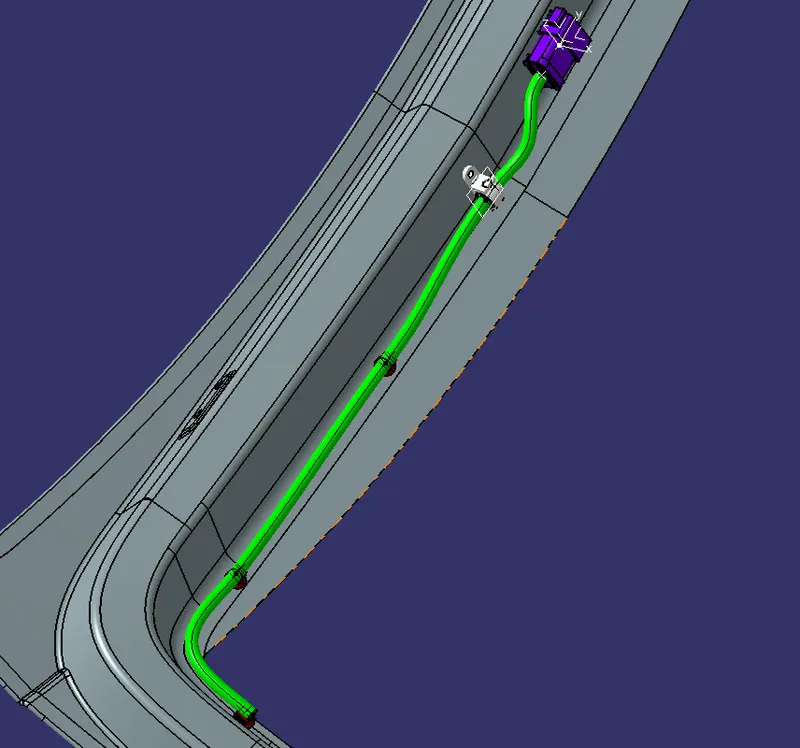
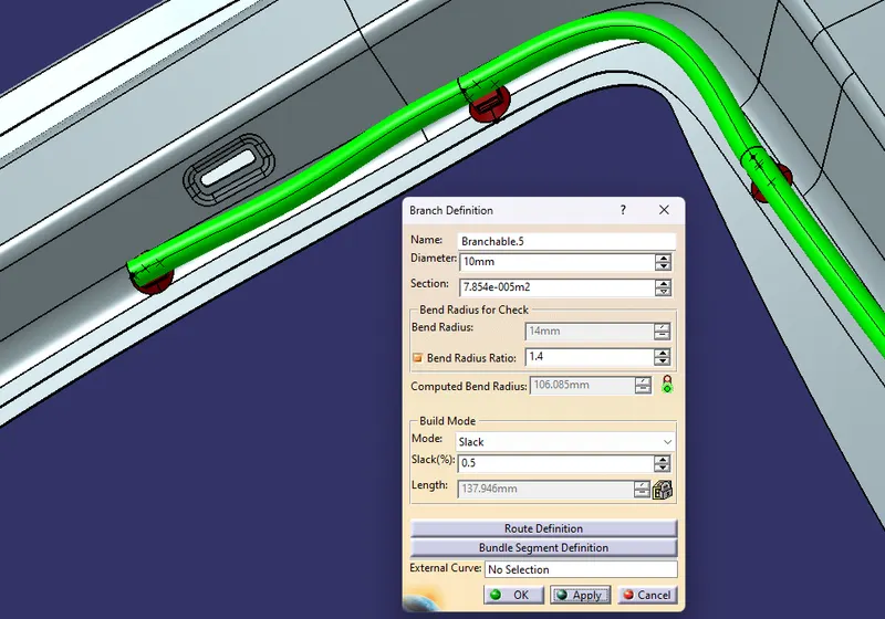
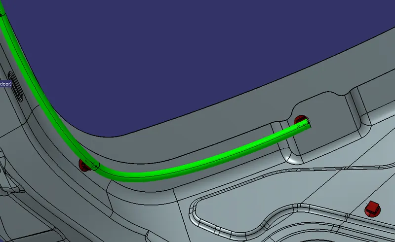
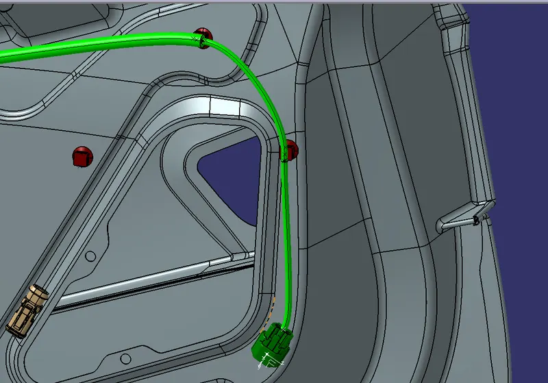
STEP 4 - Bundle routing
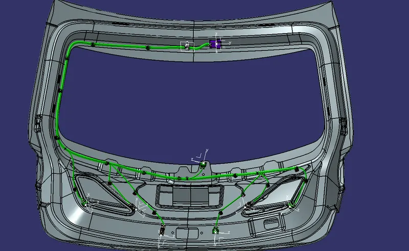
PROTEECTION CIVERING:-
Protective covering:
Corrugated tubes, Convolutes, Sleeves and many other types of coverings are used to protect the wiring harness. Graphical representation of coverings are applied on bundles.
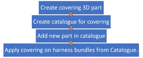 |
|
Creating Corrugated tubes. |
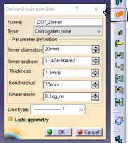
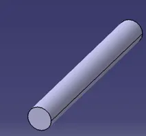
For creating corrugated tubes, switch to electrical part design workbench, click on protective covering definition and then select the plane where the corrugated tubes are to be created. A popup opens as shown in Fig. 34. Give the inner diameter, thickness and bend radius (generally 1.5 times the outer diameter) and click ok. The corrugated tube will be appeared on the screen. Save the part.
 |
 |
|
Defining the protective covering. |
|
Now create a catalogue for COT tubes, so they can be used anytime it is required.
|
Creating Corrugated tubes. |
To add the protective covering to the bundle, switch to electrical assembly design, select the protective covering definition. Now select the bundle that requires the covering a pop up will open up as shown in Fig. 34. In protective covering tab, click on catalogue box and select the required COT tube.
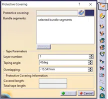 |
|
Protective covering. |
After selecting the bundle, the length of the tube can be changed by adjusting the start and end extremities point. This helps in fixing the COT tubes at a certain distance from the connector ends.
Insulations: are adhesive/non-adhesive tapes and sleeves. They are made from PVC or cotton/polymer materials.
 |
|
Tapings. |
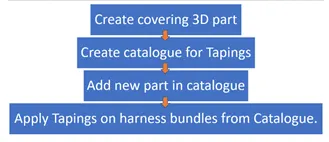 |
|
Creating insulation taping. |
Creating the insulation tape is same as that of the corrugated tubes.
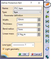 |
|
Creating insulation tapes. |
Create catalogue same as corrugated tubes for PVC and cotton tapes and name it as insulations. Insulations are also added to the branches same as corrugated tubes by protective covering definition in electrical harness assembly workbench.
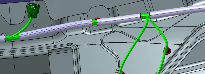
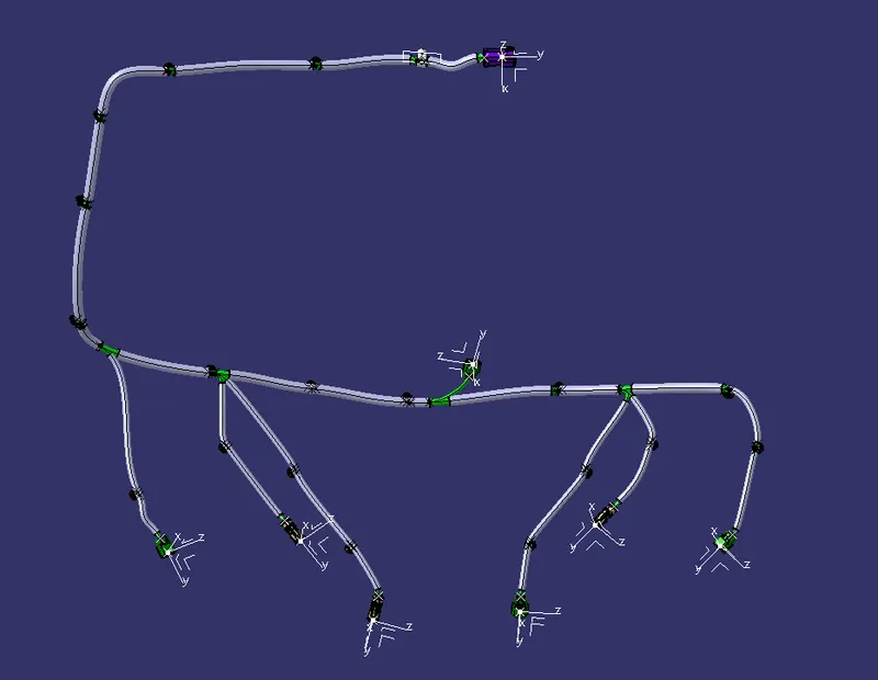
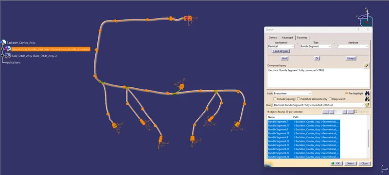
BUNDLE CONTINUITY CHECK:
USING COMPOSED QUERRY AS :- TRUE
Wiring harness Flatening
Step - 1:
- Create a product file and navigate to the Electrical Harness Flattening for wire harness flattening option and save it in the same location where the wire harness or routing assembly is stored.
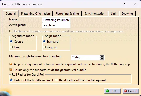
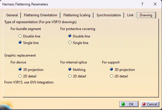
- Define the 'Harness flattening parameters' in order to flatten the required wire harness assembly.
- While defining the harness flattening parameters in the drawing menu single line is selected for bundle segment and double line is selected for protective coverings in order to differentiate between the wire bundle and cot tubes in drafting.
Step - 2:
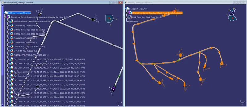
- Select the 'Extract' option from the Electrical Harness flattening workbench and select the Geometric bundle product in the wire harness assembly product file.
- Then wire harness assembly is imported to the Wire flattening product file with 'EHF' extension added to the geometric bundle assembly name.
Step - 3:
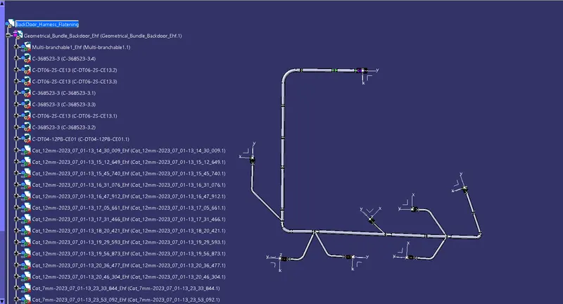
- Select the 'Flatten' option to flatten the wire harness assembly.
- Then select the active plane, then select any one branch and then select the 'select all branches'.
- If there is no discontinuity in the bundle segment then all the branches will be selected and by pressing 'ok' the wire harness assembly will be flattened.
Step - 4:
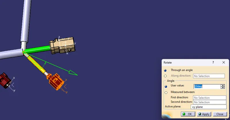
- Use 'Rotate' and other commands to rotate the branches and bring them in proper orientation as per the given layout.
Step - 5:
- Save the product file using 'Save management' option so that all the related product files and part files are stored in single directory.
FOR DRAFTING:
Step - 1:
- Create a new drawing file and save the file in the same location.
Step - 2:
- Insert the title block template and fill up the required details.
Step - 3:
- Add the front view of the harness assembly by selecting any one of the flat faces of the connector and orient the view as per the requirement.
Step - 4:
- Go to the properties of the view and select the '3D Wireframe' on and ' Is always visible' option in order to see properly the Wire bundle, connectors and the protection coverings.
Step - 5:
- Show and name all the parts used in the wire harness assembly in form of a table.
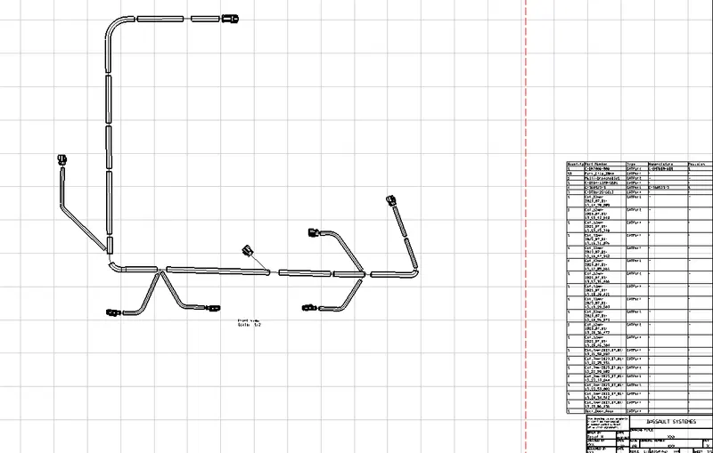
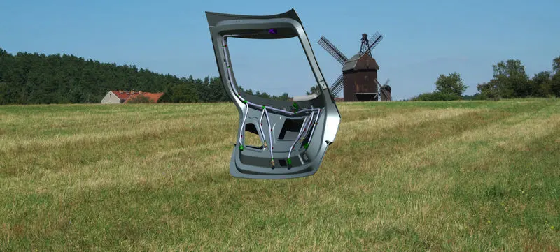
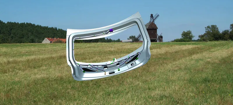
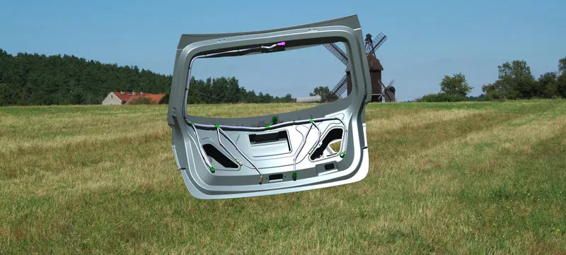
FINAL_VIEW :-
CONCLUSIONS
- The wiring harness basics and the industrial practices are studied.
- Different connectors and their installation in 3D modeling are practiced.
- The protective devices and their application at the required region in the wiring harness bundle are practiced.
- Electrical workbenches in CATIA V5 such as electrical part design, electrical assembly design, electrical assembly harness, electrical harness flattening are exercised.
- 3D representation and 2D drawing of the engine harness are implemented.
- Backdoor harness is taken as a case study and developed the geometrical bundle assembly without fouling the bundle segments.