CREATE MOLD FOR CPU FAN BEZEL CONSISTS OF CORE & CAVITY BLOCK ALONG WITH SLIDERS & WASHERS
HERE I CREATE COMPLETE MOLD FOR CPU FAN BEZEL IN WHICH I'LL CREATE INSERT, HOLE FOR NUT TO HOLD INSERT, SLIDERS, WASHERS, SPACE FOR WASHERS IN CORE AND CAVITY, SPACE IN CORE FOR LOCKING MECHANISM, SPRUE, RUNNER, GATE, AIR VENTS.
1. SCALE
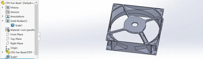
First step in creation of mold is to scaleing component as per it's shrinkage value so in the case of ABS plasticit is 6% so we have to scale it 106% = 1.006. It is done by using scale cammand in mold tool.
2. DRAFT ANALYSIS & PARTING LINE
- DRAFT ANALYSIS
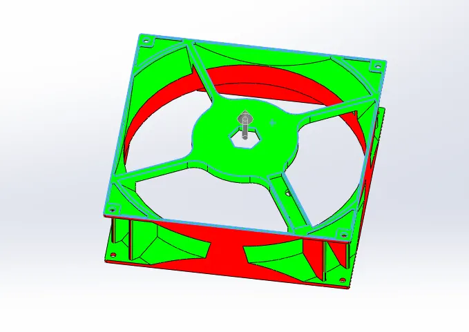
- After scaling component i'll do draft analysis in which i have to select first tooling direction and then draft angle. It is done by using draft analysis which is in mold tool.
- PARTING LINE
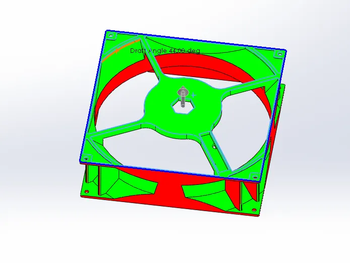
- Now i'll create parting line, parting line is the line describes that where core and cavity surface get separated. It is done by parting line cammand where first we have to select tooling direction and draft angle. Then a blue line will generated that's the parting line for the component.
3. SHUTOFF SURFACES
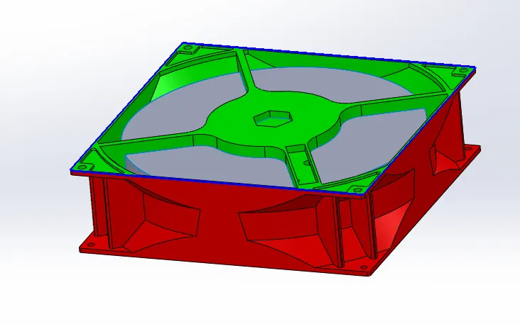
- This the final and important cammand for creating surfaces for core and cavity, shutoff surfaces splits the core and cavity block. Shutoff surfaces are created in open regions of coponents and in some cases we have to create it by our own & usually is done by using shutoff surfaces in mold tool.
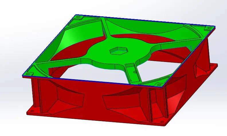
- Shutoff surfaces are created using loft surfaces and surface fill cammand, copy the created surface and knit them with earlier created surface for core & cavity.
4. PARTING SURFACE
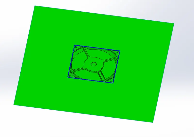
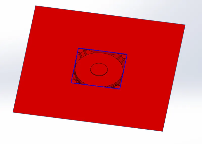
Create one constrain on surface where parting line is generated and apply surface fill cammand hence surface is created and trim the surface using trim tool as parting line keep outside portion only.
- cavity
- core
Here working with component is over from here i'll continue in assembly part as created core and cavity surfaces
ASSEMBLY
1. Our first step in assembly is to import the component and create two new part using cammand new part in insert component and save them externally name as core steel
and cavity steel
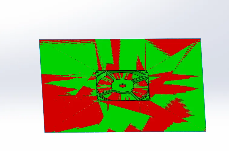
2. Edit the core part start sketch and extrude for creating core block then offset surface by 0.00 mm and using cut with surface cammand remove extra material.
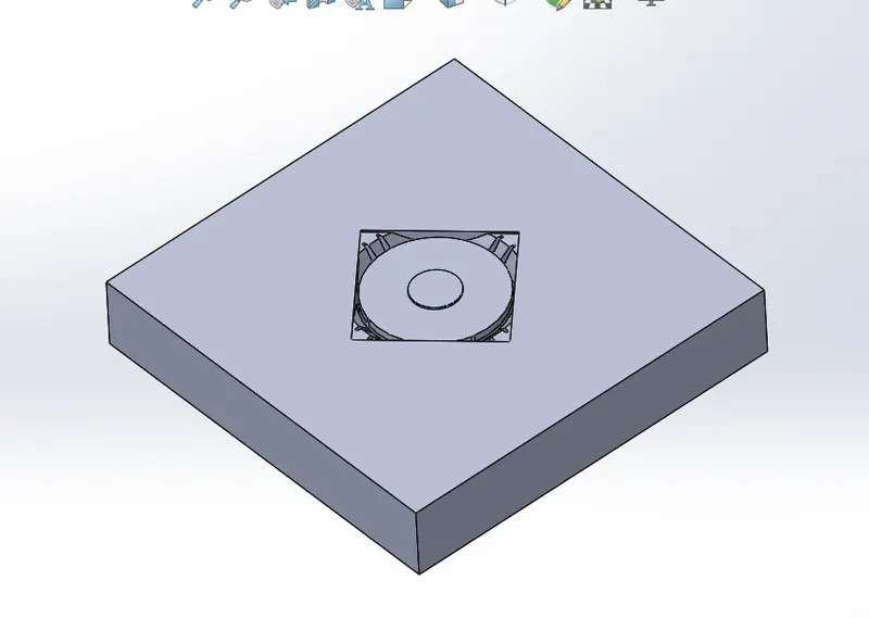
3. After creation of core mold some undercuts are present so for that i have to create sliders using split cammand also i have to create insert and hole in core mold using split & hole cammand only.
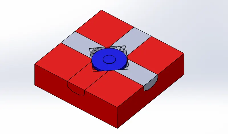
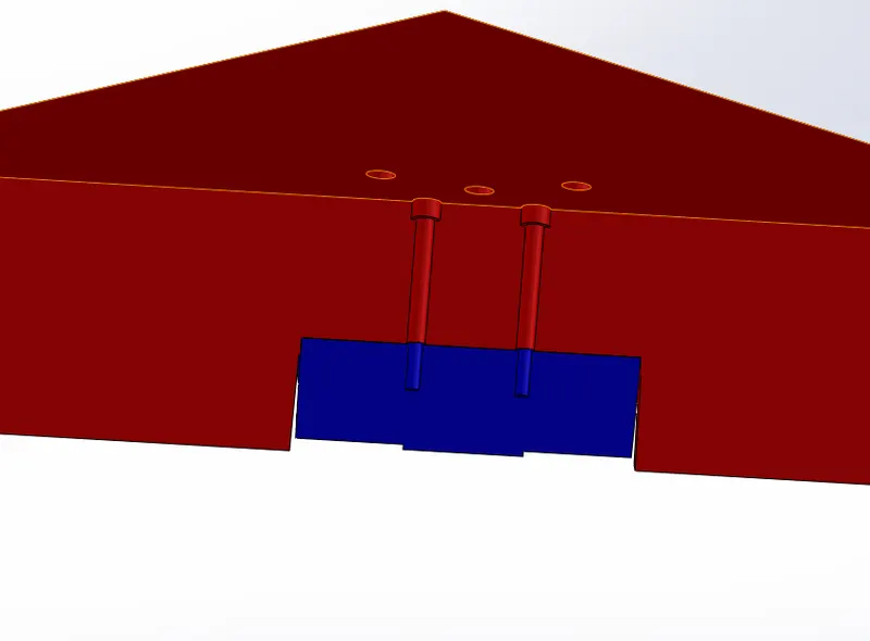
SAVE THE SLIDERS EXTERNALLY IN PARAMETRIC FORMAT USING "INSERT INTO NEW PART" CAMMAND THEN AND DELETE THE SLIDERS PART FROM CORE STEEL FILE
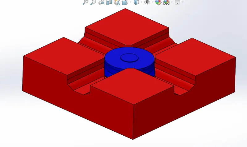
4. In assembly create new part and name it as sliders, open the slider and import parametric model of slider and remove some material and for holding washers create some materials, and again save it in paramatric format.
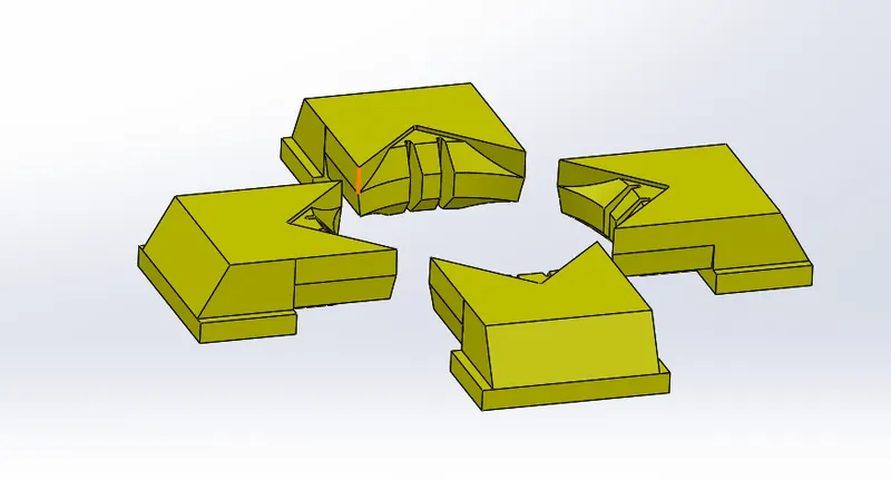
5. Open core part and import recently saved parametric model of sliders & using combine (substract) cammand create space for slider in core part and using move face, extrude cut cammand remove material from core steel part to give passage for sliders and holding washers.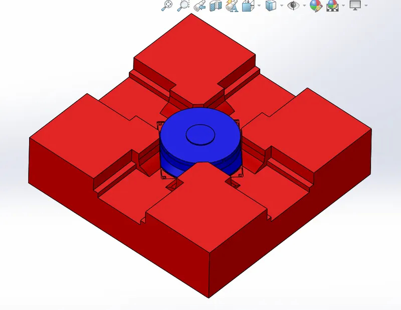
6. In assembly create one new part and name it washers, edit washers and create washers and come out then fix it on it's proper position with core steel part.
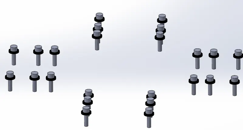
7. Open core steel part and create holes for wasers and space for locking mechanism using extrude cut cammand.
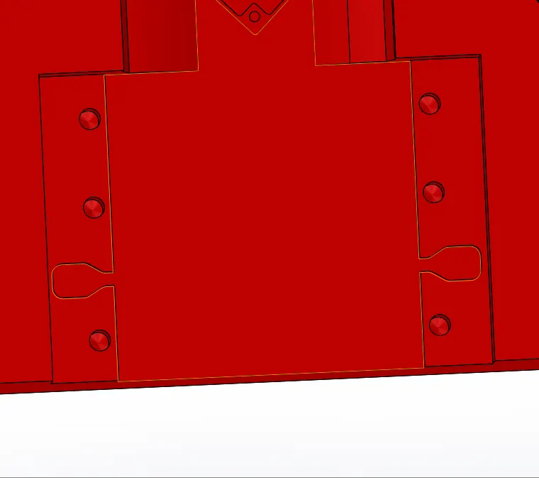
8. Open cavity steel part and import slider part first i'll create some material then using combine (substract) cammand remove some materal and also remove material for clearence of washer.
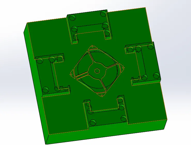
9. In cavity part i'll create sprue and runner using extrude cut cammand on top face of cavity steel part.
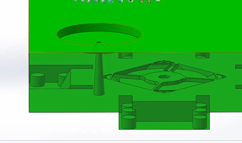
10. Open core steel part here i create gate using creating body and use the body in combine (substract) cammand to remove material to that a space will be created.

11. In core steel part i have to create air vents it is very important that traped air inside cavity must flow out so incoming material should come in, i'm using split and combine (substract ) cammand to do it.