MODELING AND RENDERING OF BIKE
1. MODELING AND RENDERING OF AMERICAN CHOPPER USING SOLIDWORKS
2. OBJECTIVE
- Model the different parts of american chopper using solidworks.
- Assemble the parts of chopper.
- To create a photo realistic view of american chopper by rendering the model using solidworks photo view 360.
3. PART MODELING
- Part Modeling in general means to create a virtual prototype of an item which is used for various purposes , all parts are need to be assemble together to get final product.
- FEATURES DESCRIPTION
- SKETCH
- Sketch is two dimentional representation of the model with respect to plane.
- Sketches are used to perform various oparations either solid or surface.
- Various seketches are like point, line, arc, spline, circle, rectangle.
- OFFSET
- Sketch entities ,modeled edges such as spline, arc are recreated with similar geometry with same distance apart from its parent entities.
- EXTRUDE BOSS
- Extrude is a feature in solidworks to convert 2D sketches in 3D model.
- FILLET
- Fillet creates round face on the 3D modeled part.
- Fillet can be applied either on face edges ,corner or requeired sharp edges on 3d body.
- LOFTED BOSS
- Loft is used to generate complex geometry in single feature.
- Loft is done by interpolating surfaces between various cross section of model like sketches, faces, or edges.
- DOME
- Dome is used to round the flat surface of body.
- Created round surface may be spherical or elliptical.
- EXTRUDE CUT
- Extrude cut is feature used to remove materials from 3d body.
- It is opposite to the extrude boss because it removes the material according to respective sketches.
- SPLIT
- Split toll is used to devide the body as per sketches separetly.
- It ia also used to cut the body as per sketches drawn.
- TRIM ENTITIES
- Trim oparation is performed to trim the surface , body or any sketches.
- Trim has many options like powe trim ,extend.
- REVOLVE
- To create revolve feature sketch must have center line or axis.
- In revolve feature sketch should be selected and it's axis line too.
- DYNAMIC MIRROR
- It is an important tool in solid works to mirror your entities about an axis.
- Mirror can be done to 2D sketches as well as 3D body.
- APPEARENCES
- An appearences defines the visual properties of a model including colour and texture.
- It not affects properties which are defined by materials.
- It gives the attractive look to the model.
- COMBINE
- Combine feature is used to combine or join manually two bodies.
- SHELL
- Shell is used to define thikness of thin and thick shell elements.
- CHAMFER
- A cut on the edge or corner of body that makes it slope slightly
- CIRCULAR PATTERN
- A circular pattern is used to create different number of instances required create the pattern circularly
- LINEAR PATTERN
- A linear pattern is used to create copy of bodies in certain linear direction.
4. SURFACE MODELING
- Surface modeling gives you ability to build out a visual representation of an object's exterior it's countours.
- Parts like seat, fuel tank are modeled
- FEATURES DESCRIPTION
- LOFTED SURFACE
- Loft surface are generated by multiple 3D curves or existing edges creating a smooth tangency between selected curves.
- FILLED SURFACE
- It constructs a surface patch with any number of sides, with in boundary defined by existing model edges sketches or curves including composite curves
- SURFACE TRIM
- Priminilary used to cut away material from surface.
- It provides two modes standerd and manual
- EXTEND SURFACE
- Extend surface is used to extend the surface which is already created.
- There are different options available on the extended surface.
- SURFACE KNIT
- Surface knit joins two free edges of surface together.
- It reduces the gap between the two edge of surface.
4. PARTS MODELED FOR AMERICAN CHOPPER
- The following parts of an American chopper is modeled and assembled together.
- Transmission belt
- Kick stand
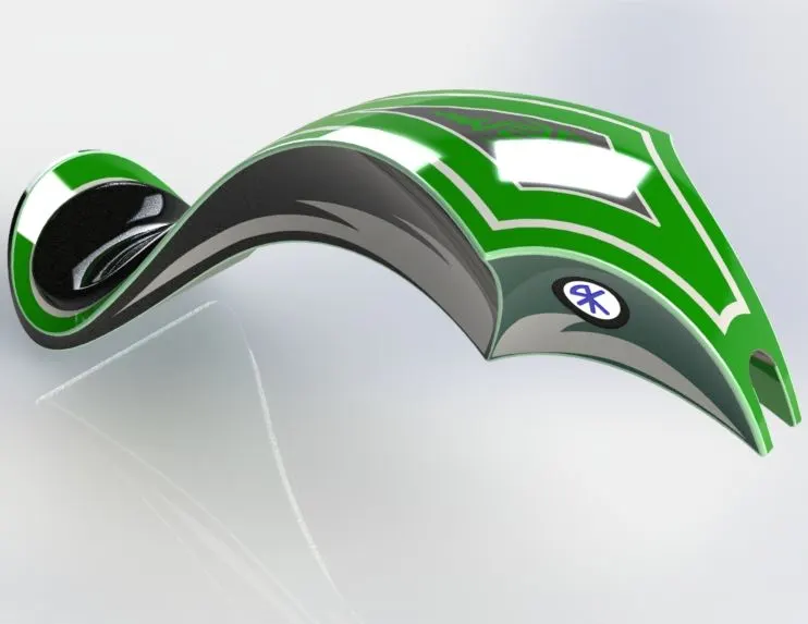
- Front fender
- Rear fender
- Chain
- Oil tank
- Peddle
- Front wheel
- Rear wheel
- Front fork
- Chassis
- Engine
- Gas tank
5. DESCRIPTION OF PARTS AND FEATURES USED
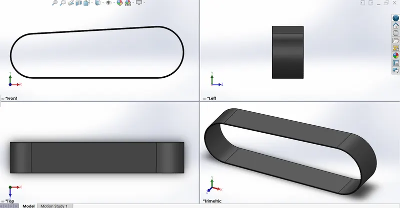
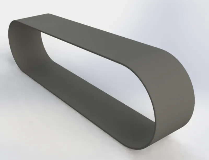
- TRANSMISSION BELT
- It is loop of flexible material used to link two or more rotating shaft mechanically.
- Most often it is parallel, but here it is non parallel because it links two different diameter of rotating shaft.
- Belt transfers power and motion from one shaft to another.
- FEATURES USED
- Boss extrude
- Fillet
- KICK STAND
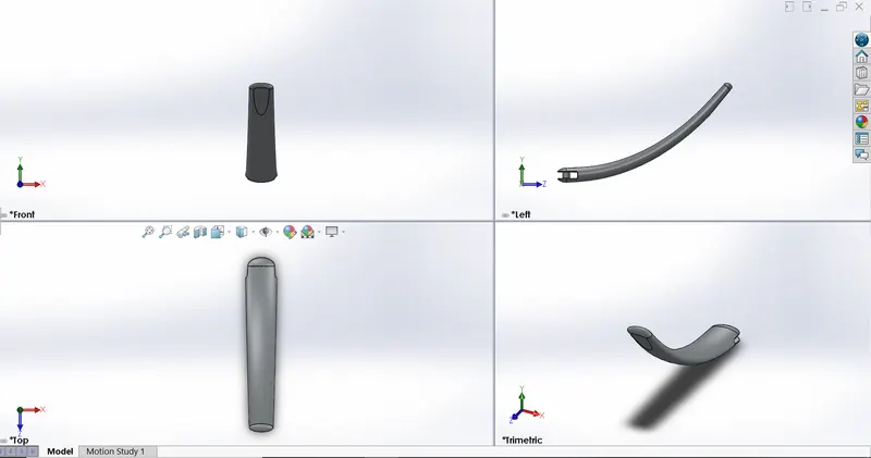
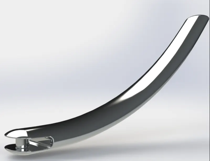
- Kick stand is a device in motorcycle which uphold the bike without leaning on another object or aid of person.
- A kick stand is a metal piece that can flip down from fram and make content with ground.
- It is generally located in the middle of bike or it's center of gravity
- FEATURES USED
- Loft
- Dome
- Cut extrude
- Split
- Boss extrude
- Fillet
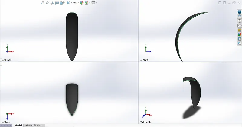
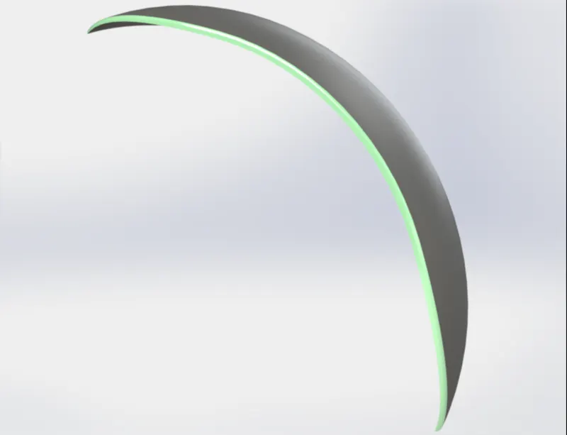
- FRONT FENDER
- Fender is an American english term called part of an automobile.
- It's main purpose is to prevent sand, mud, rock, liquid and other unwanted material thrown by moving tyre
- FEATURES USED
- Revolve boss
- Split
- Fillet
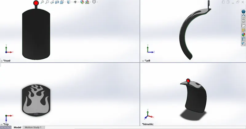
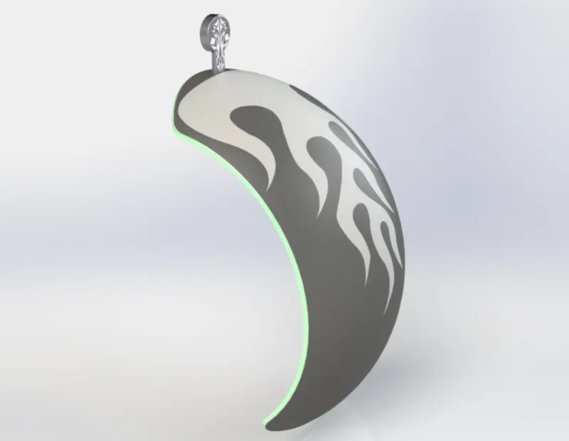
- REAR FENDER
- As priviously explained fender is an american english word which means motor cycle part.
- It's primary purpose is to prevent sand, mud, rocks, liquids and other unwanted material thrown by moving tyre.
- FEATURES USED
- Revolve boss
- Split
- Fillet
- Shell
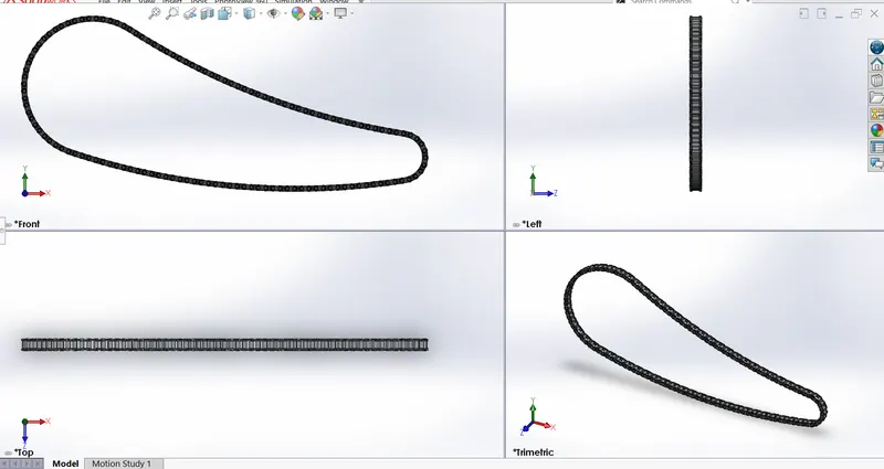
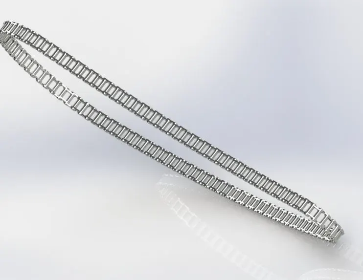
- CHAIN
- Chain is very essential component used in bike for power transmission.
- It transfer mechanical power and motion from engine output shaft to their respective wheels.
- FEATURES USED
- Extrude boss
- Fillet
- Projected curves
- Curve pattern
- Mirror
- OIL TANK
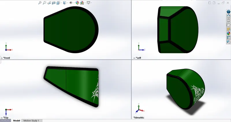
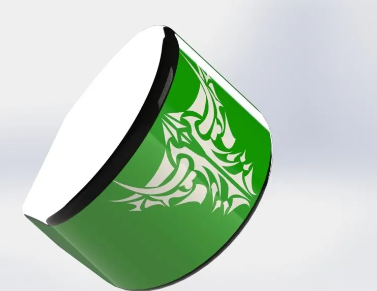
- Oil tank is used in motercycles to store lube oil to lubricate the engine parts to avoid wear and tear due to extreme heat.
- FEATURES USED
- Extrude boss
- Fillet
- Shell
- Combine
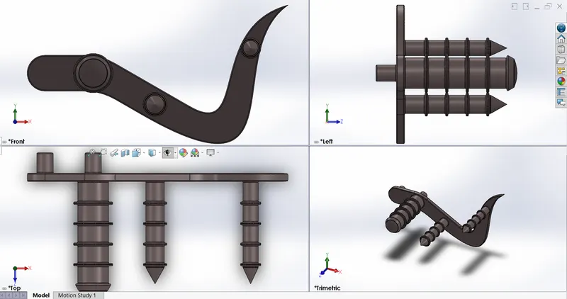
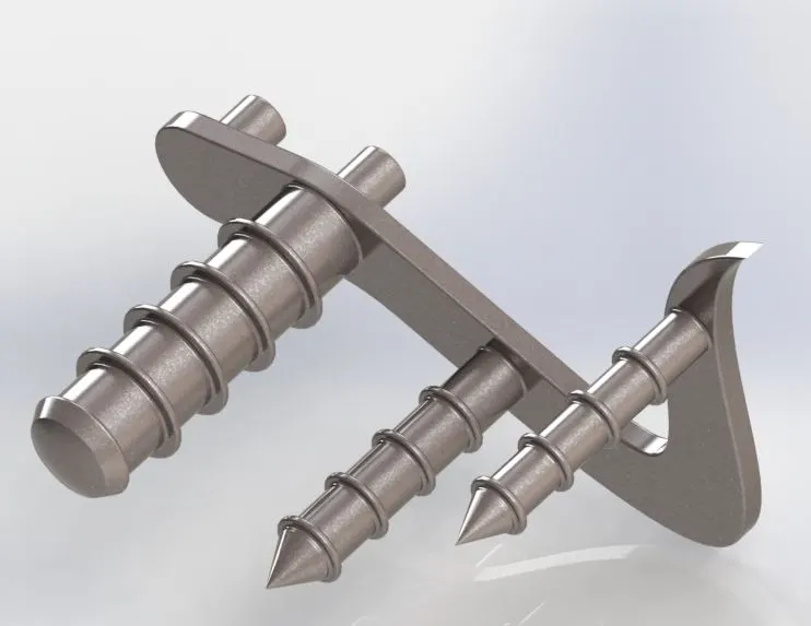
- PEDDLE
- A peddle has the function of shifting gear to get the desired speed from engine and also apply breaking force.
- FEATURE USED
- Extrude boss
- Fillet
- Revolve boss
- Dome
- Chamfer
- Linear pattern
- FRONT WHEEL
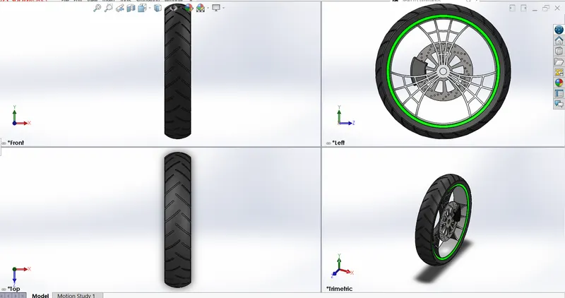
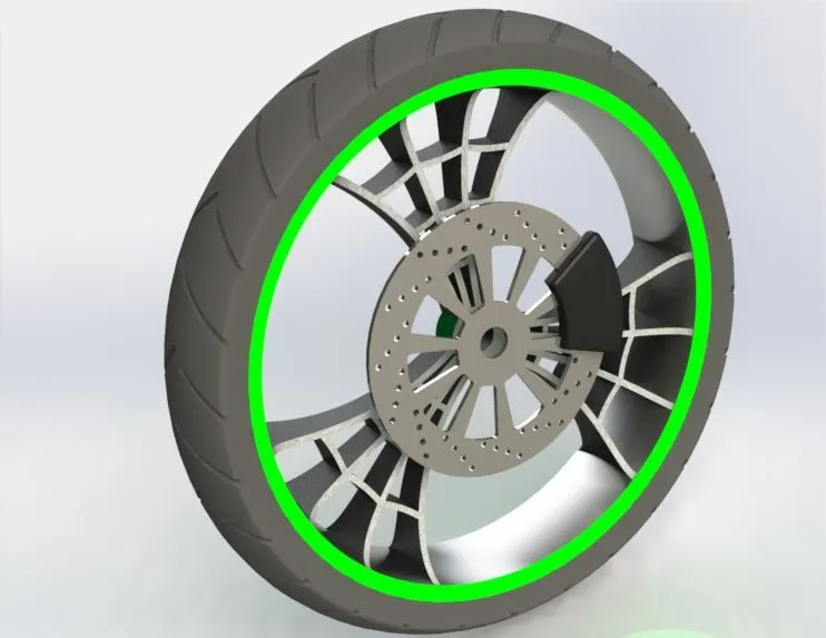
- A wheel is a circular block of a hard and durable material where the center has been bored with a circular hole through an axle bearing about which rotates
- FEATURES USED
- Extrude boss
- Cut extrude
- Revolve cut
- Circular pattern
- Combine
- Fillet
- Chamfer
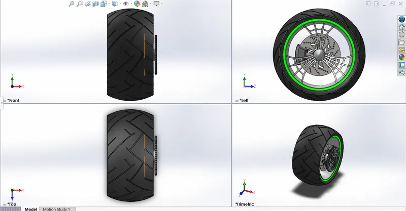
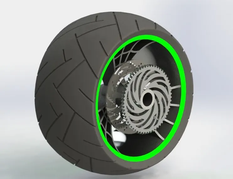
- REAR WHEEL
- A wheel is a circular block of ahard and durable material where the center has been bored with a cirular hole through an axle bearing about which the wheel rotates
- FEATURES USED
- Extrude boss
- Cut extrude
- Revolve cut
- Circular pattern
- Combine
- Fillet
- Camfer
- FRONT FORK
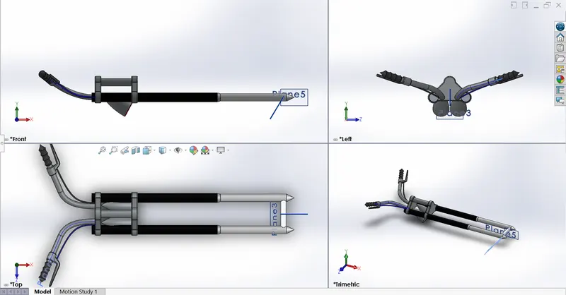
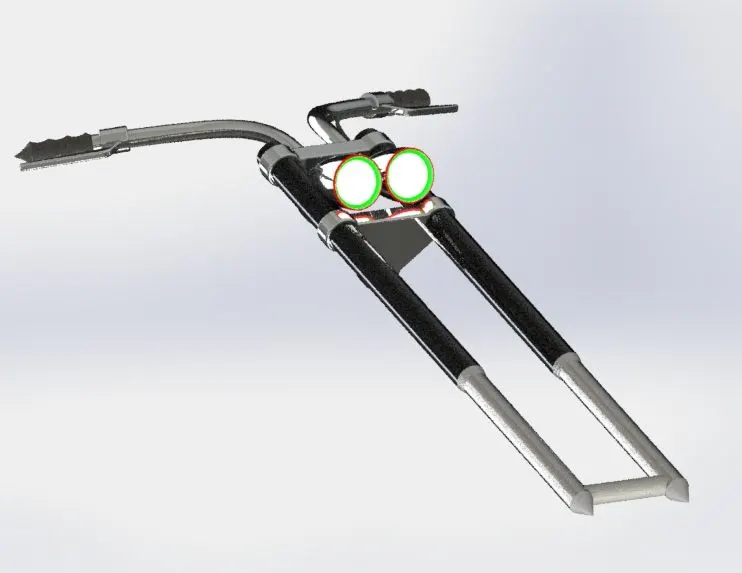
- A bicycle is the part of bike that holds the front wheel.
- A fork consists of two blades which are joined at top by frok crown.
- FEATURE USED
- Extrude boss
- Revolved boss
- Fillet
- Extrude cut
- Dome
- Revolved cut
- Swept boss
- Projected curve
- Mirror
- Combine
- CHASSIS
- The chassis mostly consists of hollow tube which serves as a skelton for the gearbox, engine, front fork, peddle, kick stand are mounted
- FEATURE USED
- Swept boss
- Projected cuve
- Mirror
- Extrude boss
- Fillet
- Extrude cut
- Dome
- Combine
- Chamfer
- Split
- Revolved boss
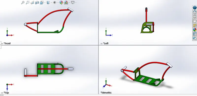
- ENGINE
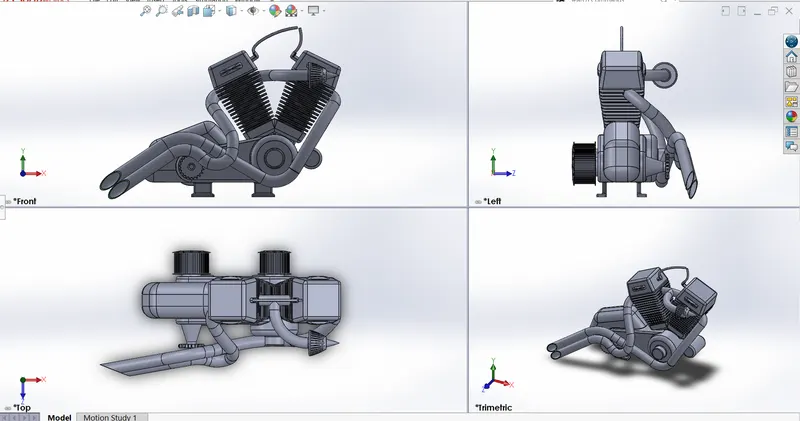
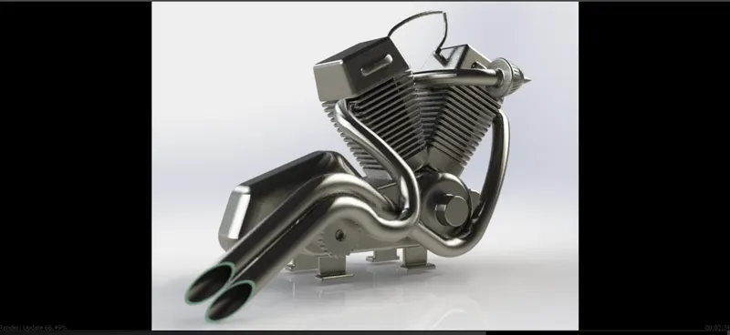
- An engine or motor is a machine designed to convert one form of energy into mechanical energy.
- Heat engine like IC engine burn a fuel to create heat which is then used
- FEATURES USED
- Swept boss
- Project curve
- Mirror
- Extrude boss
- Fillet
- Extrude cut
- Dome
- Chamfer
- Split
- Revolved boss
- Linear pattern
- Composite curve
- GAS TANK
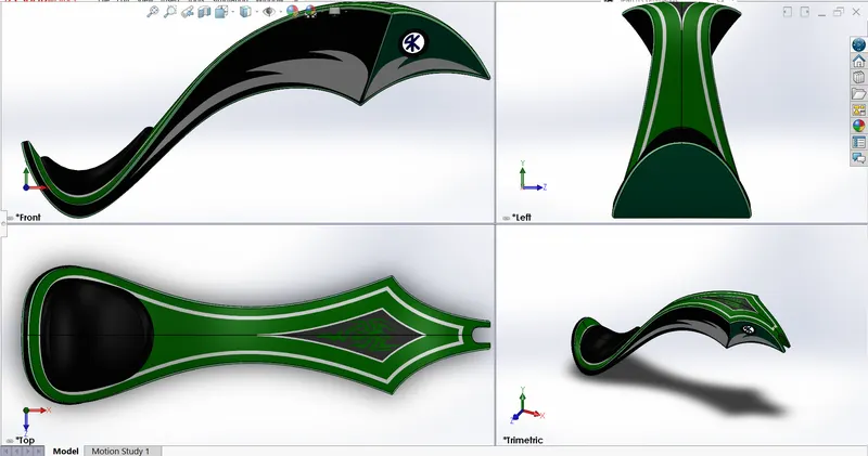
- A gas tank or petrol tank is a storage tank of petrol which is stores petrol in it.
- Through storage tank fuel is pumped into engine.
- FEATURES USED
- Surface loft
- Surface knit
- Project curve
- Fillet
- Swept surface
- Split
- Mirror
- Swept cut
- Plane
6. ASSEMBLY OF AN AMERICAN CHOPPER
- MAIN ASSEMBLY
- Intially the chassis part is inserted in the assembly by using insert part in the option.
- After that parts of chopper is inserted in assembly then click ok to fix the chassis.
- After that the other part of chopper is inserted into assembly and give possible mate condition
- FEATURES USED TO ASSEMBLE THE AMERICAN CHOPPER
- Mates
- Insert part
7. FEATURES DESCRIPTION USED TO ASSEMBLE AMERICAN CHOPPER
- MATES
- Mates create geometric relationships between assembly components.
- As we add mates we define the allowable directions of linear or rotational motion of componet.
- We can move or rotate component within it's degree of freedom.
- INSERT PART
- We can insert the other components which need to be mated together
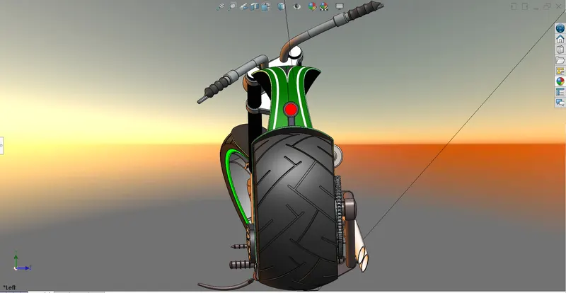
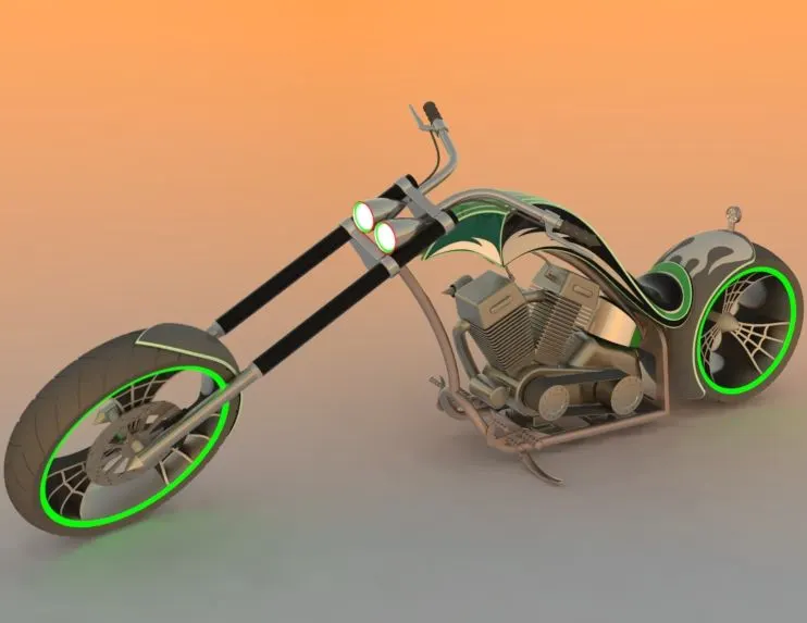
8. RENDRING
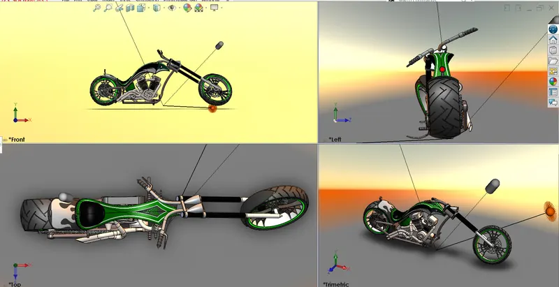
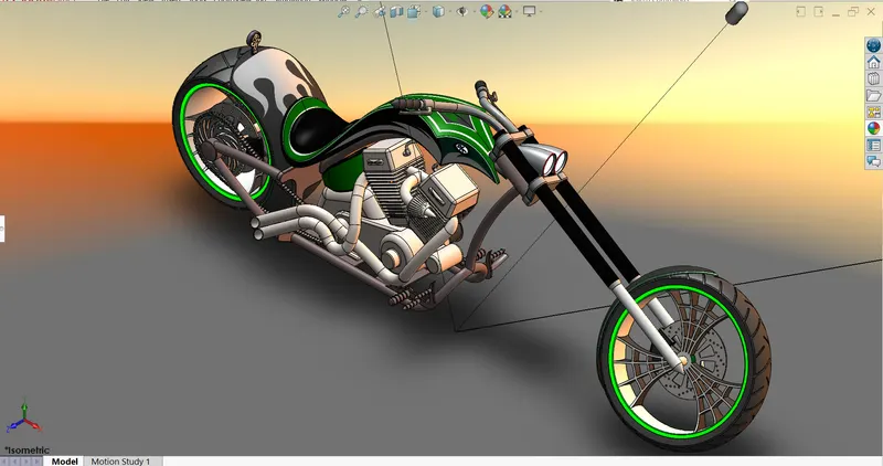
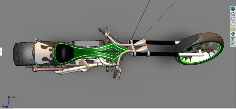
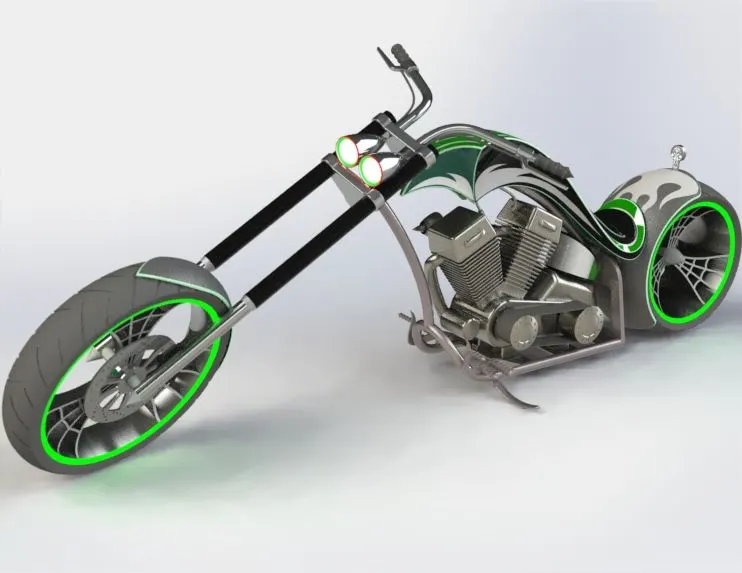
- Rendering is a process of creating realistic images of phorealistic model with environment.
- Rendering has been done in two ways in solid works. And the ways are (a) photo view 360 (b) solidworks visualize.
- In the photo realistic model some of mate condition and positions are changed to render realistic model.
- Then the photo realistic model is rendered into realistic images with diffrent views.
- Here i have used both the phto view 360 and visualise for rendering the assembled model
9. CONCLUSION
- The parts of american chopper are modeled.
- The parts are inserted into assembly and american chopper is assembled.
- The photo realistic image was renderd with use of either photo view 360 or solidworks visualise.
- I would like to thank my mentor "M.R SOUNDAR RAJAN" for helping me with the challenges.