Project 2
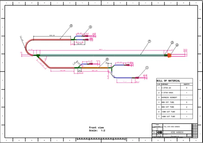
Project 2- Wire Harness in Tail Gate
Objective:
Route the Wiring harness on Given car body and Prepare flatten view drawing in CATIA V5. Application of all Packaging rules, Industry best practices studied in this course shall be demonstrated in design.
Apply Protection coverings as required.
Tail Gate Harness
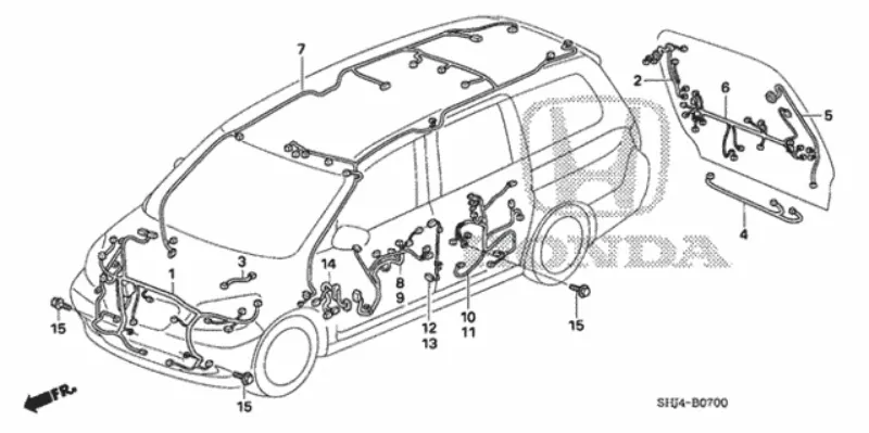
Design Criteria and Packaging Assumptions:
When designing a wire harness, there are several important design criteria and packaging assumptions that need to be considered. These factors ensure the harness meets the necessary electrical and mechanical requirements while being packaged efficiently.
Electrical Requirements:
Wire Gauge: Determine the appropriate wire gauge based on the current-carrying capacity and voltage drop requirements of the circuit.
Insulation: Select insulation materials suitable for the operating temperature, voltage rating, and environmental conditions.
Connectors: Choose connectors that are compatible with the mating components and provide reliable electrical connections.
Mechanical Requirements:
Bend Radius: Determine the minimum bend radius for each wire to prevent damage and ensure flexibility.
Strain Relief: Incorporate strain relief elements, such as grommets, clamps, or lacing, to prevent wire fatigue and maintain integrity under mechanical stress.
Mounting: Consider the mounting options and constraints within the application to ensure proper harness routing and secure attachment.
Environmental Considerations:
Temperature Range: Determine the operating temperature range and select wire insulation materials capable of withstanding those temperatures.
Vibration and Shock Resistance: Design the harness to withstand vibration and shock conditions by using appropriate mounting techniques and securing methods.
Packaging Assumptions:
Space Constraints: Understand the available space for the wire harness installation and design the packaging accordingly.
Wire Length: Estimate the required wire lengths based on the physical layout of the components and the routing path, considering allowances for serviceability and strain relief.
Wire Routing: Plan the optimal routing path to minimize the risk of interference, maximize accessibility, and avoid contact with sharp edges or high-temperature sources by ensuring connectors and components are accessible and properly labeled.
Input:
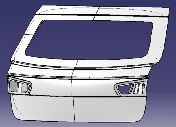
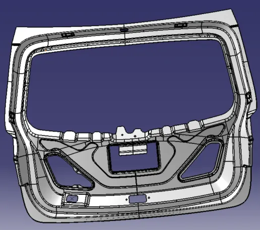
Tail Gate Inner Panel
Desgin Procedure:
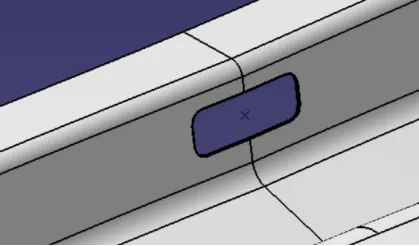
Creating cutout in inner panel, to pass the bundles and connector
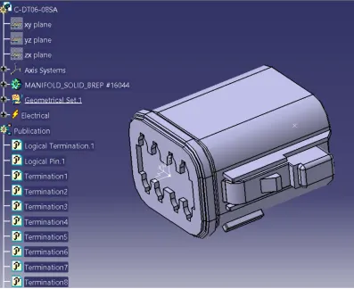
Connectors:
C-DT06-08SA
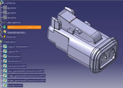
C-DT06-2S
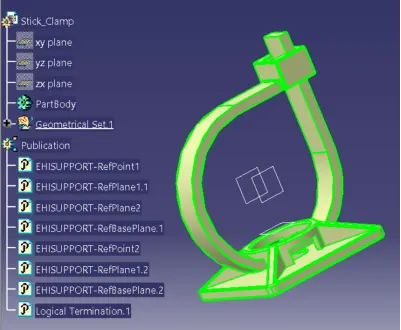
Mounting Elements:
Sticky Clamp
Harness Assembly
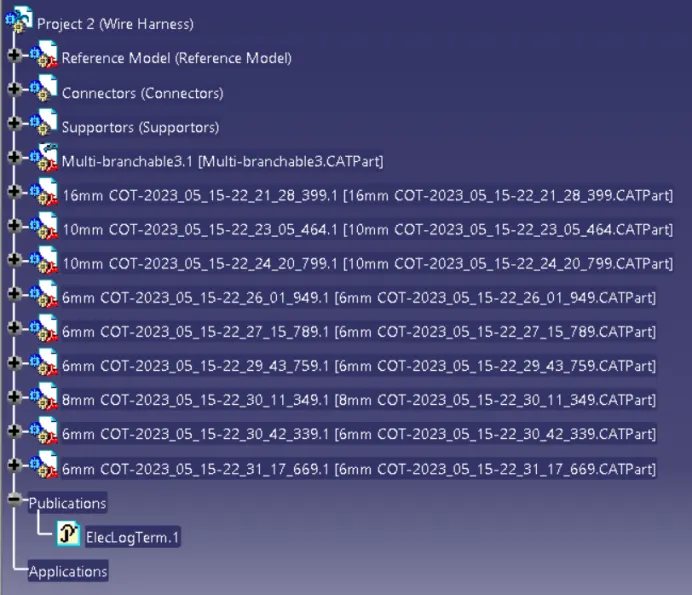
Project 2 Feature Tree
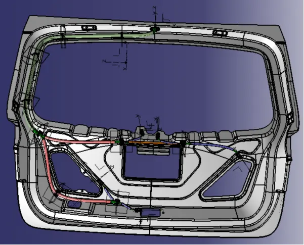
Assembly of Connectors and Mounting Clips:
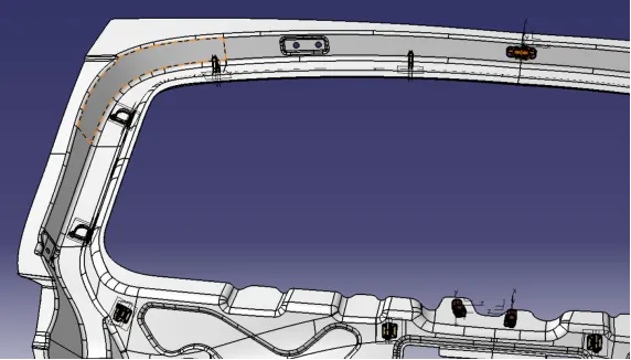
Harness Routing:
Creating the Bundle Segments:
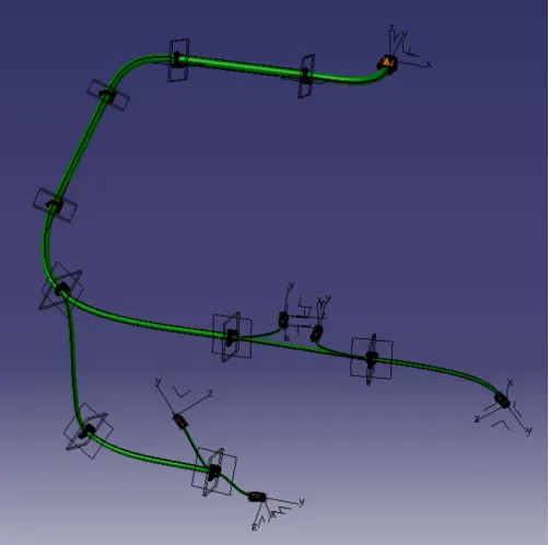
Adding COT tubes on the Bundle Segments:
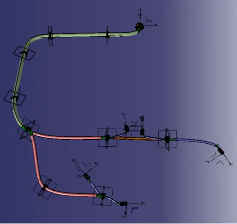
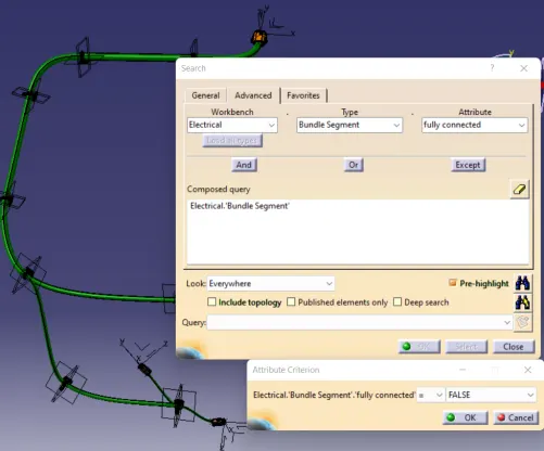
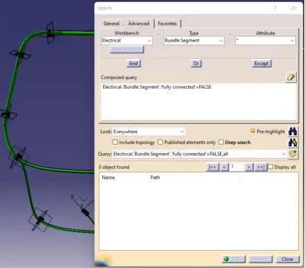
Bundle Connectivity Check:
Different Bundle View
Different Bundle Views
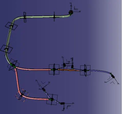
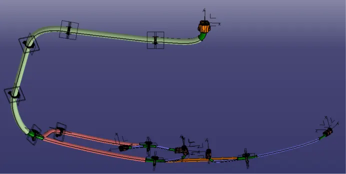
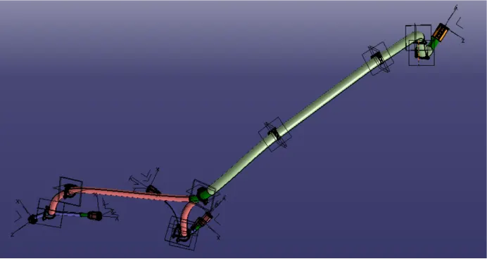
Bundle Flatten:
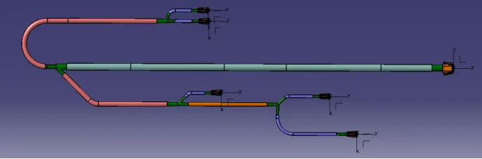
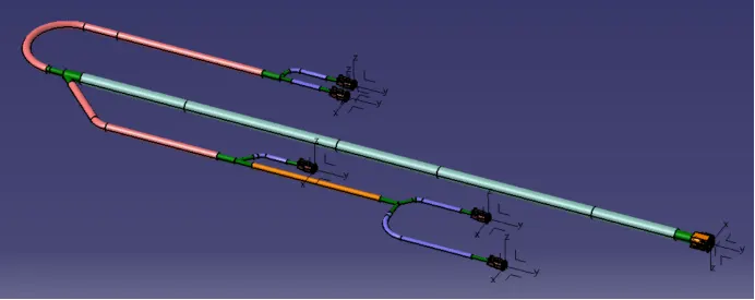
Drawing: