Project 2
PROJECT 02
wIRING HARNESS FLATTENING OF THE CAR BACK DOOR ASSEMBLY
AIM: To create the wiring harness flattening of the car back door panel assembly by following the wiring harness design rules and considerations
Objective : The main objective is to route and packagig the bundle segments for the car back door panel for the required components of the door panel by folowing the wiring harness topology , design rules and considerations
the steps to be followed is
- Create a new wiring harness context assembly product file
- Download the input door panel file
- Download the required connectors and support parts
- Define the components as electrical by defining the connector connection and the bundle connection points
- Define all the parts as the sub assembly in the conntext assembly name it as geometrical bundle
- Define the geometrical bundle as harness assembly file
- .Start routing the bundles
- Apply the protection coverings
- Save the file as the save management feature
Create a new wiring harness context file :
First of allwe need to cfeate a new wiring harness context assembly file and add the sub product files naming as the geometrical bundle and the input door panel of the car file and start assembling the components
Downlad the input rear door panel of the car and add as the new product in the context assembly
The input assembly file is
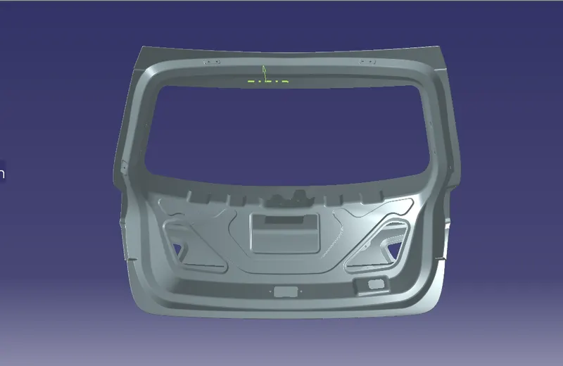
As a design engineer I has to make an idea to route the bundle segments for the vital components along side the door panel so my design for the wiring harness as follows
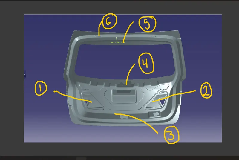
The above mentioned arte the locations for the placem,ent of the connectors for various parts along side the door panel
so i made part file which shows the reference sketch and for the connector placement
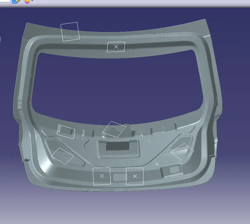
They are the
- Connector for the rear fog lamp cover
- connector for the rear fog lamp cover
- connector the number plate sensor lights
- Connector for the rear wiper
- Connector for the rear camera
- Interconnector placement
Connector for the rear fog lamp cover:
the connector used for the rear fog lamp cover is
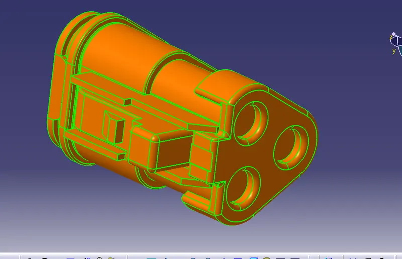
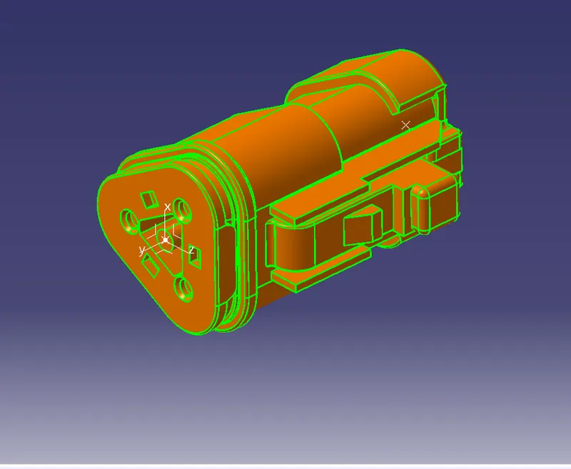
Create the reference geometry elements such as the entry points , axis system etc
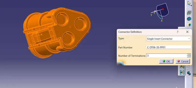
Define the part as the electrical connector by roviding no of terminations
Defin ethe bundle connection point
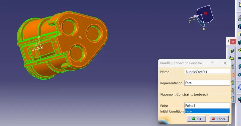
Define the connector connection points
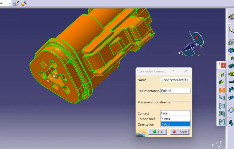
save the connector
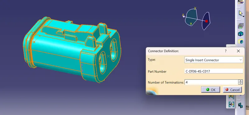
The connector used for the number plate sensor lights is
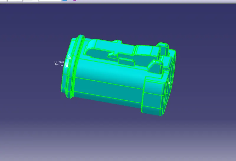
Defin eth part as the electrical connector by providing the number of terminations
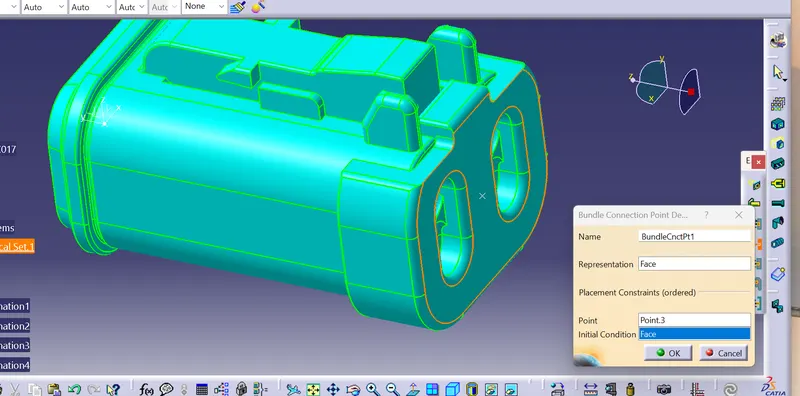
define the bundle connection point
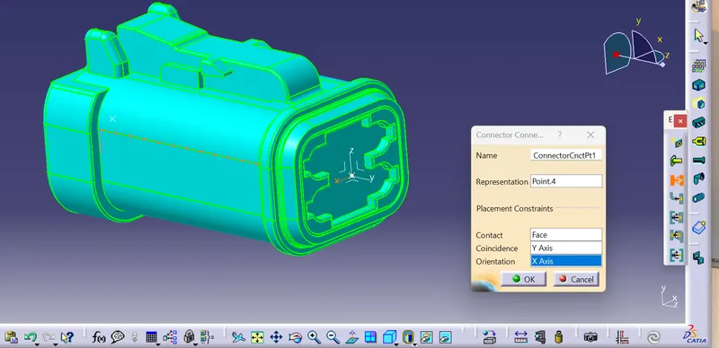
Define the connector connection system point
Save the connector
the connector used for the rear camera is
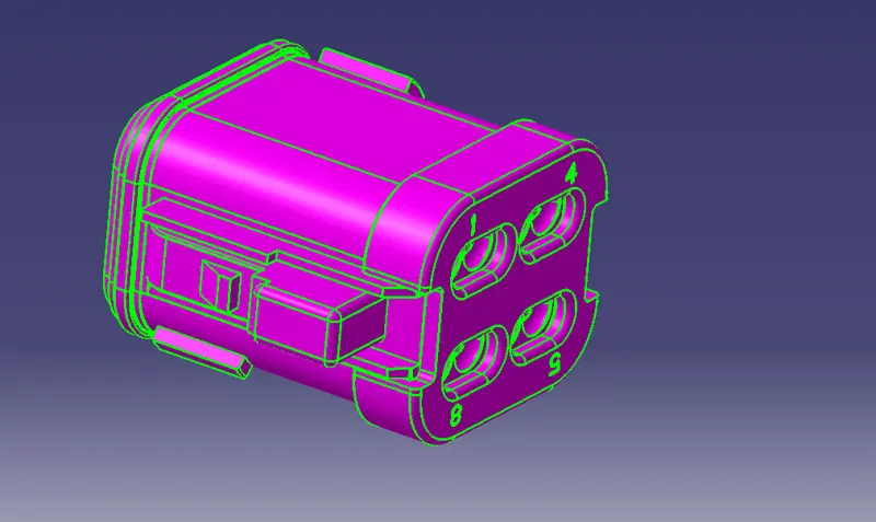
Create the reference elements
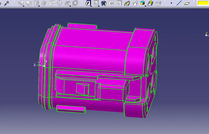
Define the parts as an electrical connector wirth number of treminations as 08
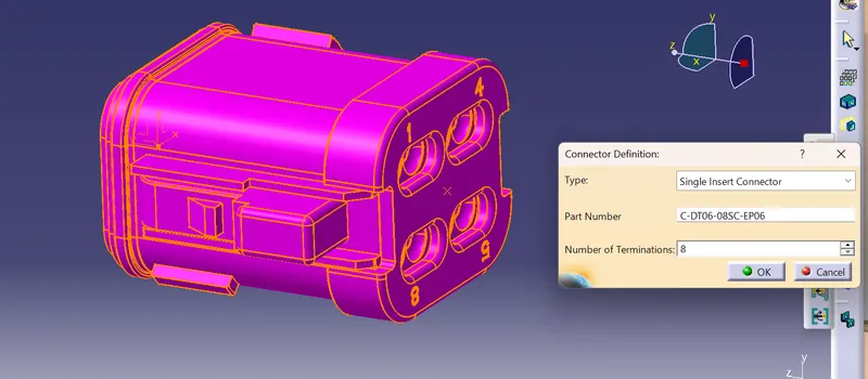
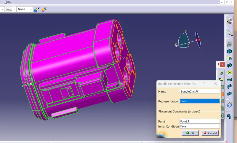
Define the bundle connection point
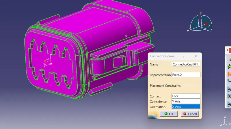
Define the connector connection point
Save the connector
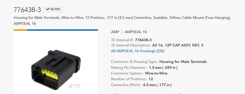
The interconnection connector is
.
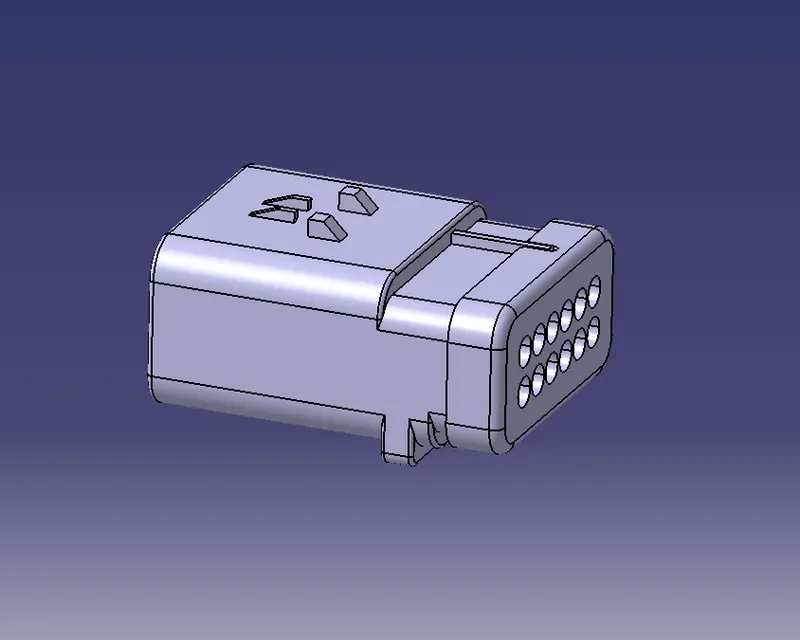
Create the reference elements
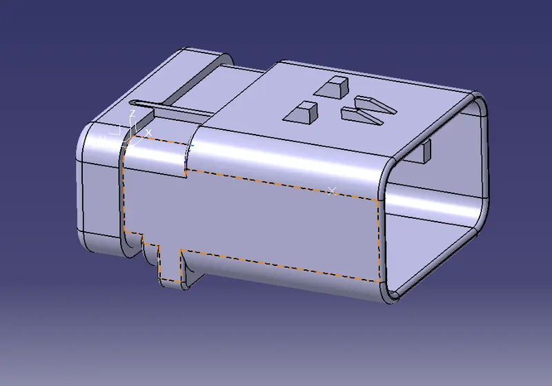
Noe p
define the part as an electrical connector
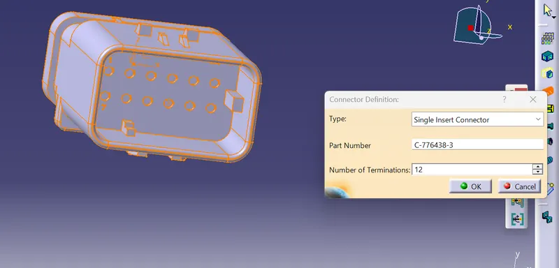
Define the bundle connection point
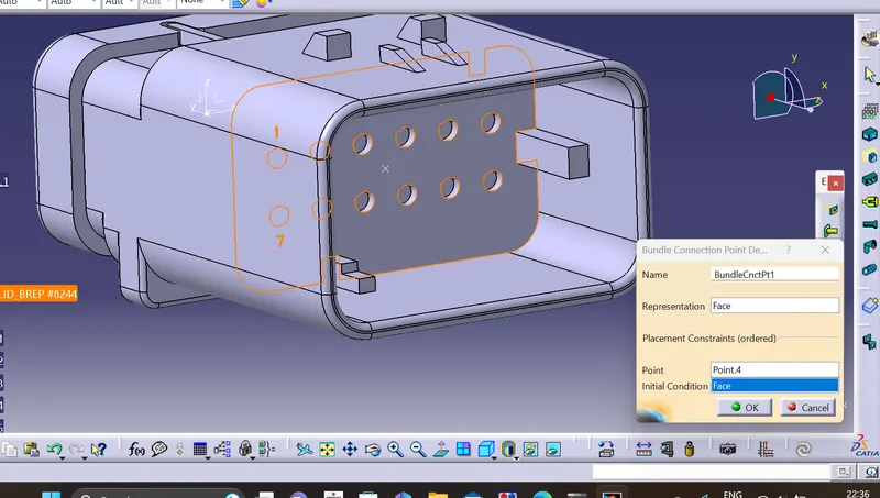
Define the connector connection point
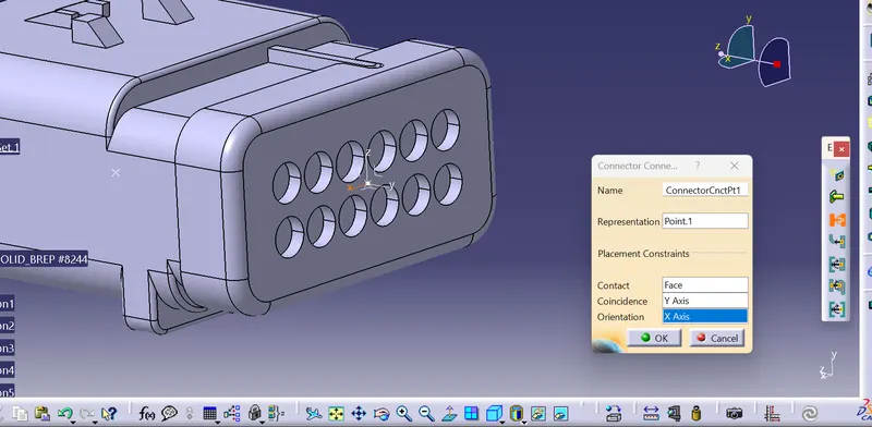
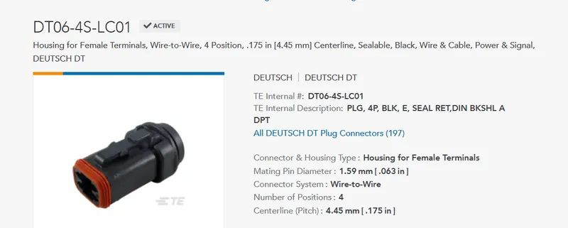
The other connector we use for the wiper assembly is
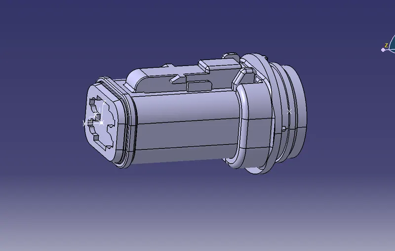
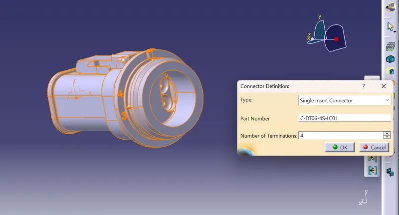
Define the part as an electrical connector.
Define the bundle connection point
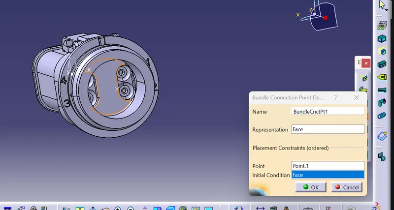
Define the connector connection point.
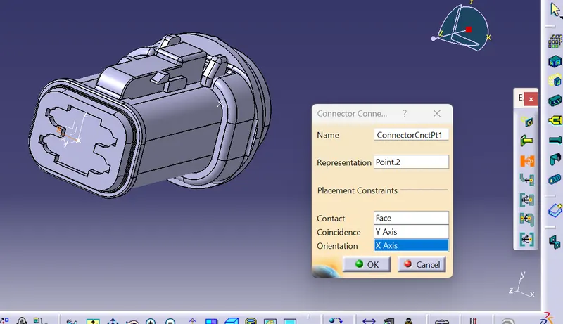
Now prepare the some mounting equipments for the wiring harness routing one of them are
- P CLAMP
- FIRR TREE CLIP
P clamp:
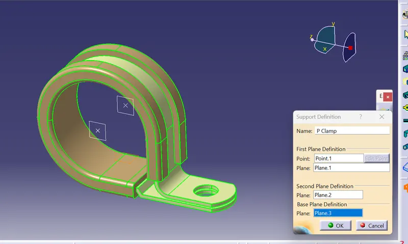
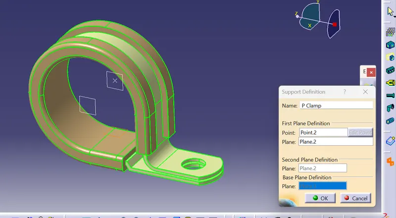
P-Clamps provide a light, fast, and efficient harness solution to cable mounting generally the p clamp hhas two bundle entry and bundle exit paths so ewe need to define the bundle connection point two times
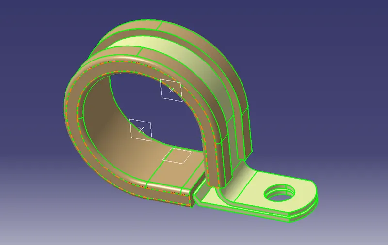
Define the part as the support electrical part.
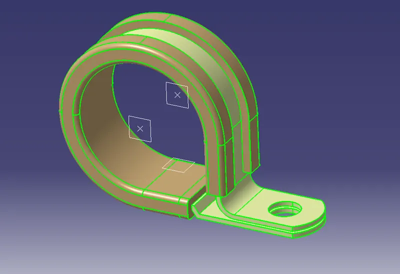
Define the bundle connection points
2.Firr tree clip:
The firr tree clip we use is
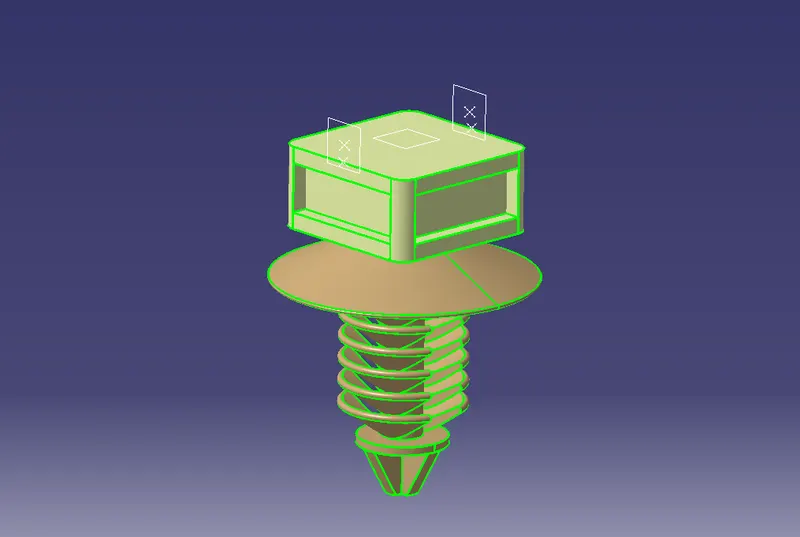
Define the part as an electrical support part.
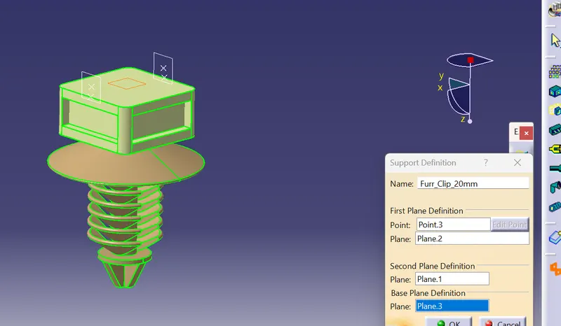
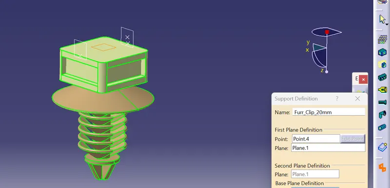
once all the parts are elctrically defined add all the components to the geometrical bundle in the context assembly product file .
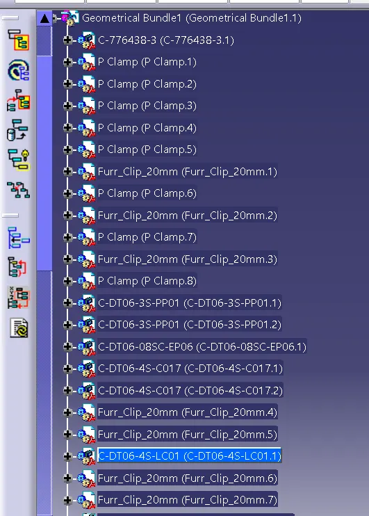
and adjusrt all the copmponents as the best routing for the wiring harness topoloy idea topology takes logical designs into the physical world. . Dynamically create installation spaces for dashboards or control panels. Define connection pathways between installation spaces and place components in spaces.
Wire harness design is the process by which an engineer evaluates the requirements of an electrical part of system, given available physical space to create an assembly of wires to deliver power and information as needed.A wiring harness is an organized set of wires, terminals and connectors that run throughout the entire vehicle and relay information and electric power, thereby playing a critical role in “connecting” a variety of components.
So arrange the conncors and the support parts foir the best routing design possible
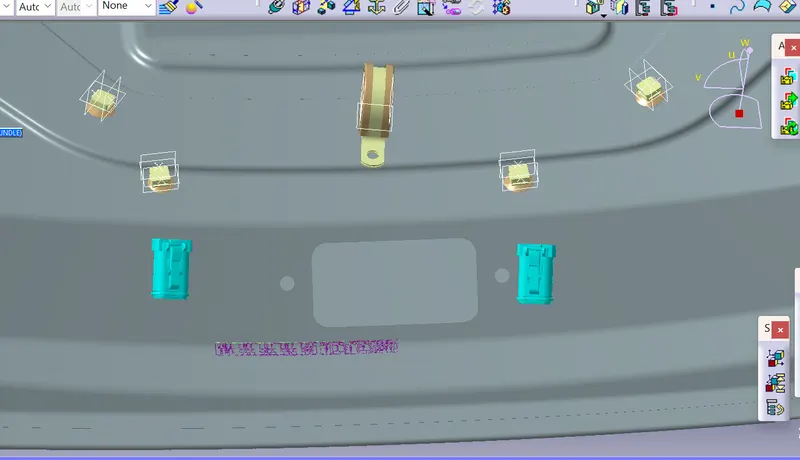
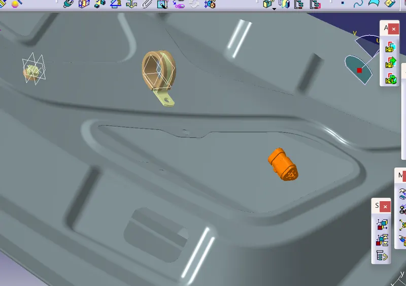
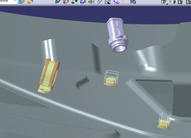
Over all view is
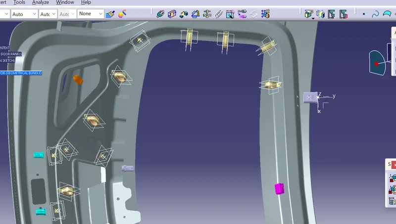
Once all the connectors and the support parets are all placed at the desired location startharnessing the wiring bundkles along side the connectors
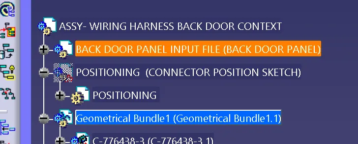
For this go to the wiring harness assembly and define the geometrical bundle as the harness electrical part and the cat product symbol of the geometrical bundle changes

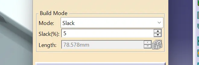
Then go to the multi branching and start defining the route defnition among the cinnectords for the flow of the bundle segments along side theb connectors and the support parts by providing the enough amount of slack because if the slack is not provided due to high amount of tension the wires may leads to brakage and damage so enough slack percentage or the extra lengh has to be provided
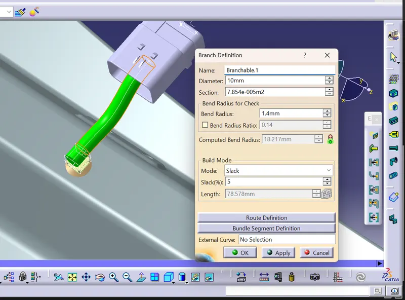
then routr the bundle defnition by providing the bundle comnnection points beteen the connector and the firr tree clip
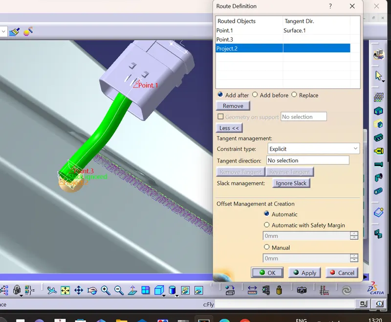
Enough slack os to be provided for the proper logical connectiion flow of bundle segments among the connectors
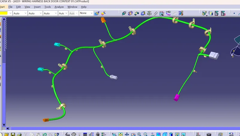
So, now continue to route the bundle among the connectors and the final wiring harness routing path is
Once all the connector are fully connected with the wiring harness routing bundlke s check for the bundle continuity whetherr all the bundles are connected with each other or not
for this we need to go to the edit< search < Advanced features < electrical workbench < bundle segement < Fully connected < true / false then it shows wthe bundle continuity whether alkl the bundles are fully connected or any dis continuity falls then we need to work on that partcular bundle segment and rectify the error to get the fully connected bundle segment flow
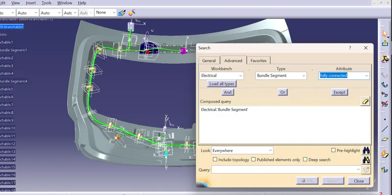
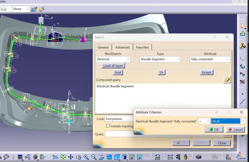
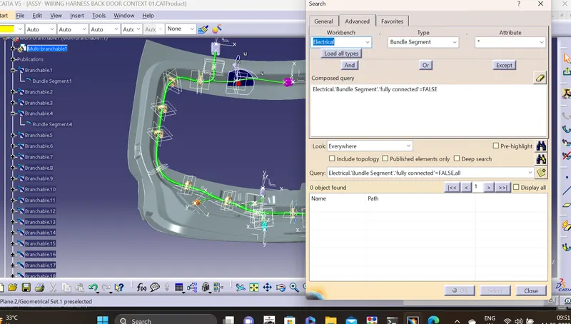
Once the bundle continuity si good apply the protective coverings such as the cot tubes
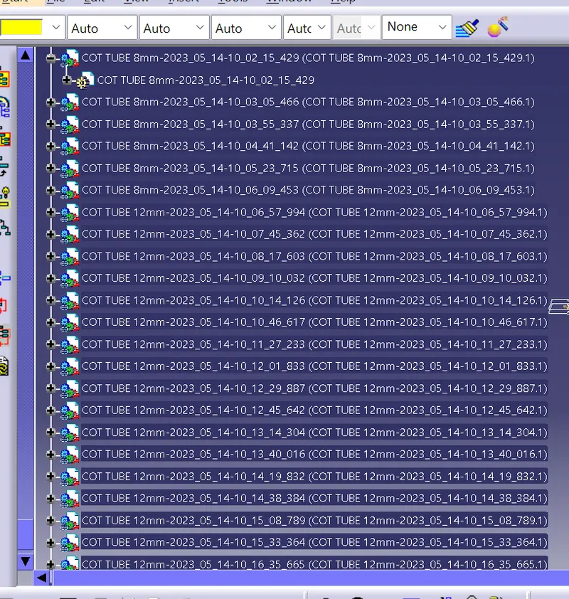
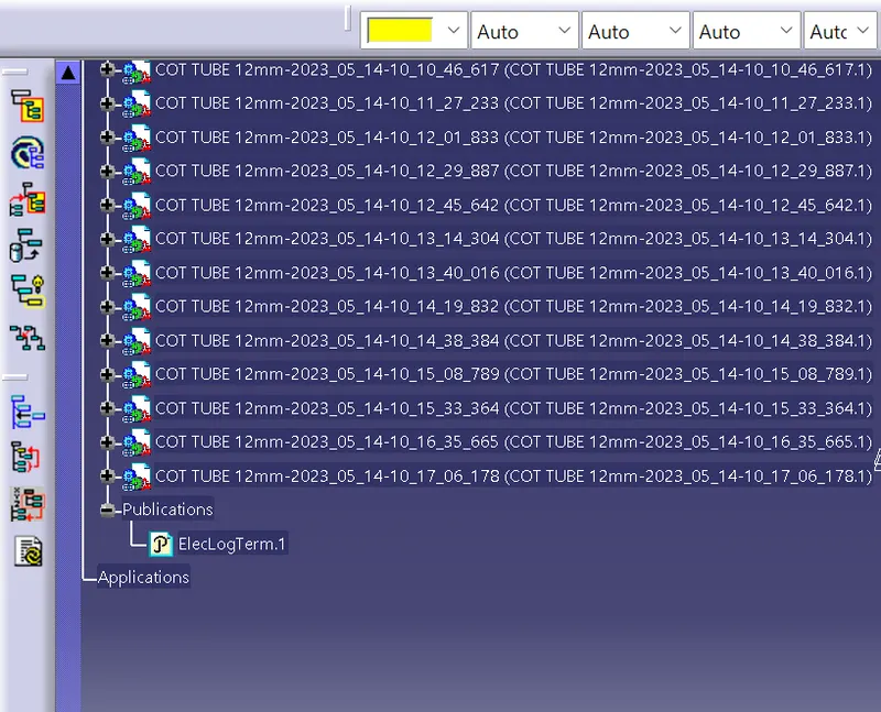
So here we use the 10 mm diameter bundle segments wires and the 6 mm bundles so we generally need to develop the 12 mm cot tubes and the 8 mm cot tubes .
The cot tubes are developed in the electrrical part design
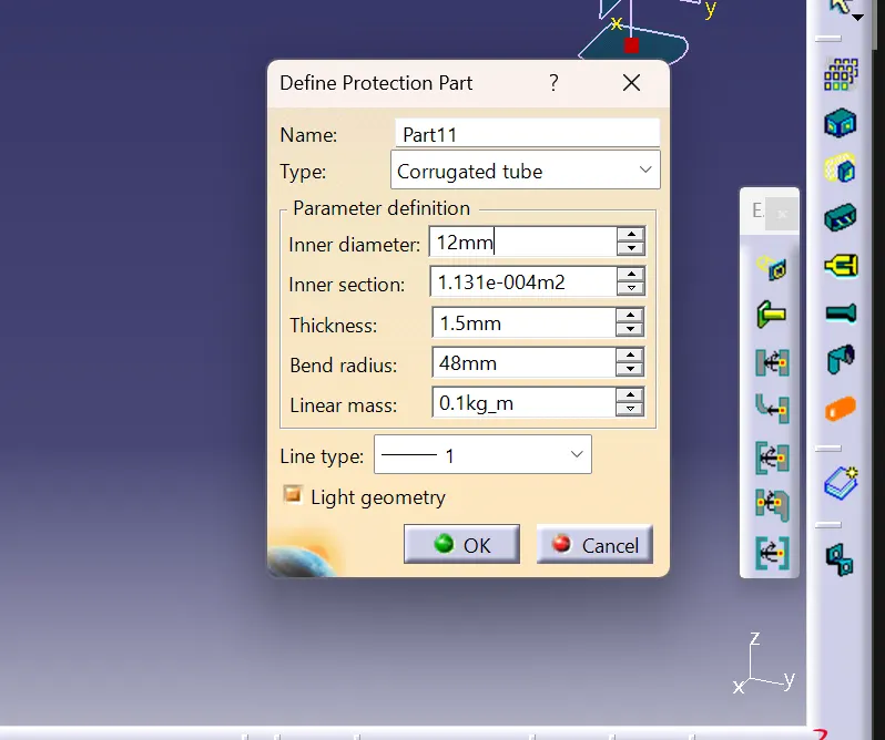
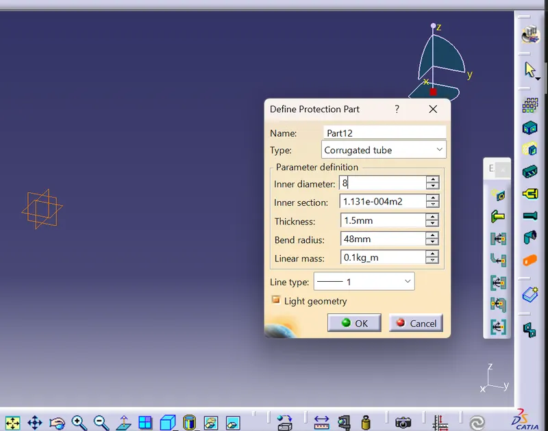
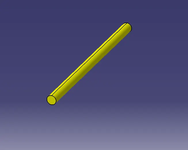
So we need to store the cot tubes in the catalogue document so that we can able to adopt them for the main cat product context assembly.
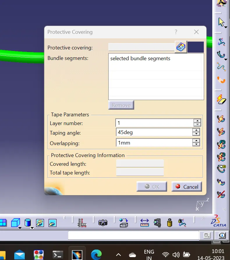
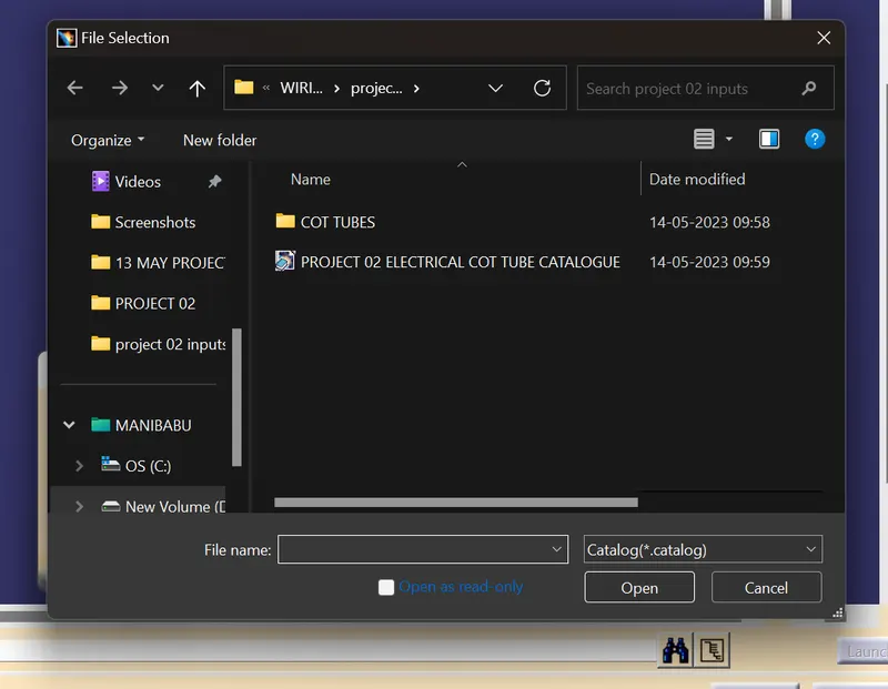
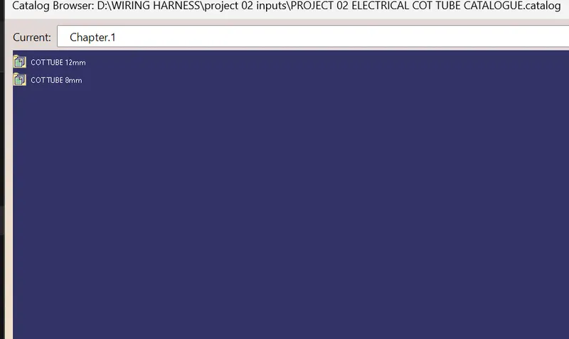
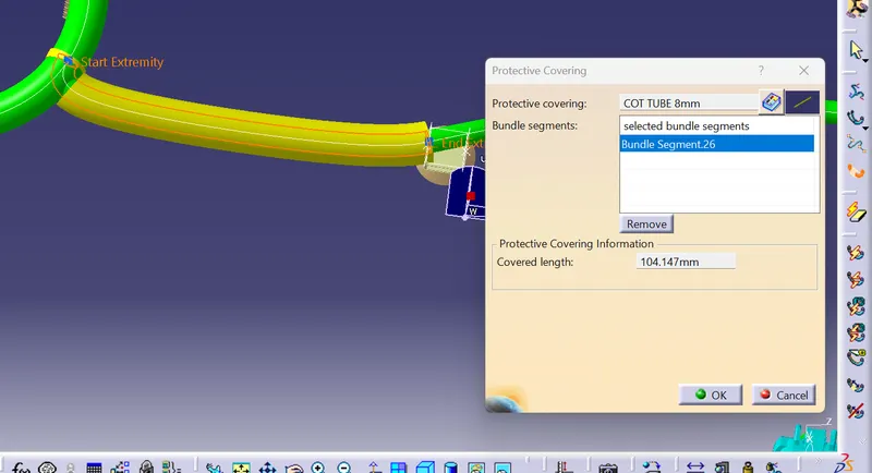
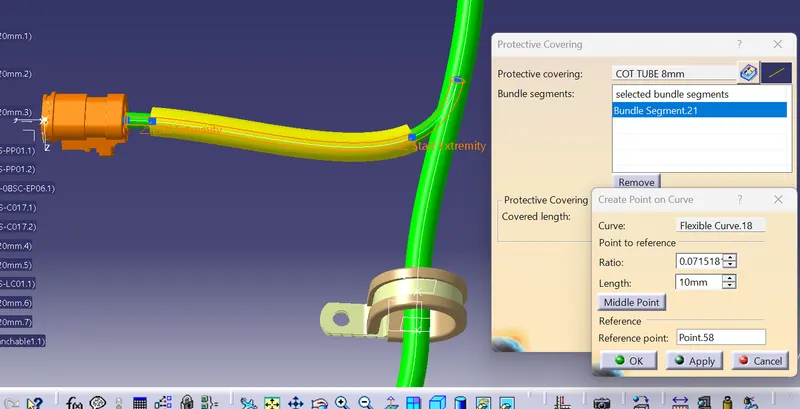
We acn alte the start extremity and the end extermity so donnt place the protective covering near the connector o the support just make sure to keep a healthy distance
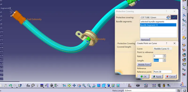
Now wrap the protective coverings across al the bundles for safe prtotection and making them as the water and teh dust resistance components .
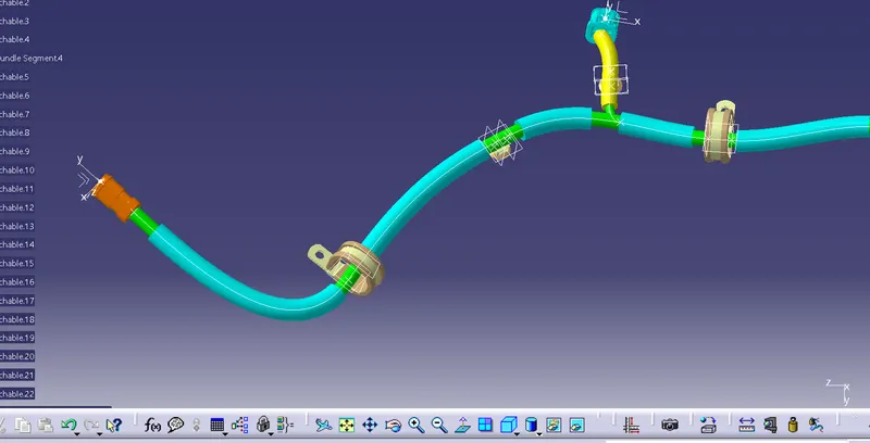
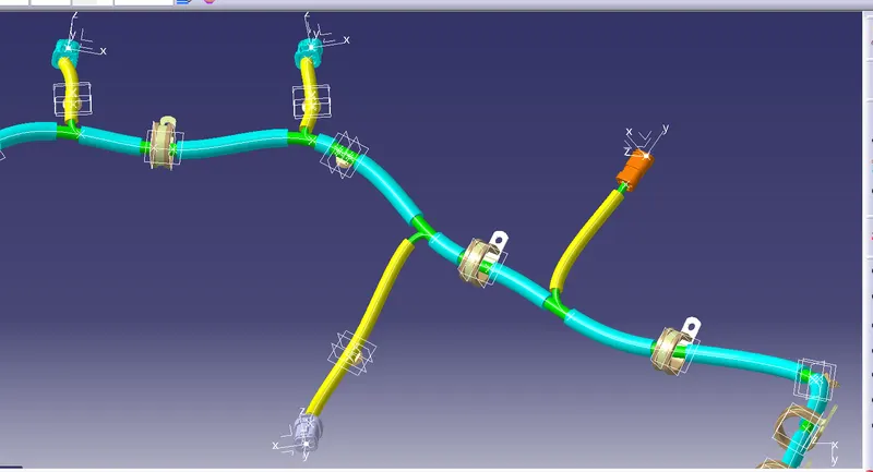
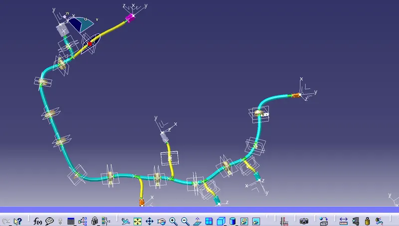
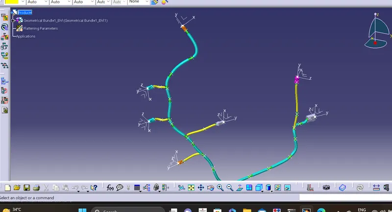
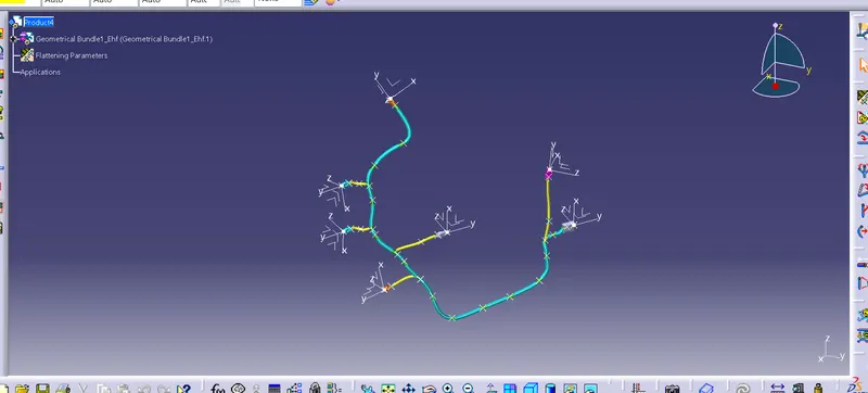
So the wiring harness is completed so we need to form the flattening of the wiring harness to represent the wiring harness as ain the form of the flattening drawing
Electrical harness flattening is one of the catia V5 feature which enables us to convert the view the wiring harness bundles in a single plane . it is necessary to check the bundle continuity before proceeds to the harness flatteneing workbench. Once the cat product file is ready fr flattening then create a new product and define some flattening properties . The settings provided for the flattening product is stored in the tree stucture
They are basically
Setting 01:
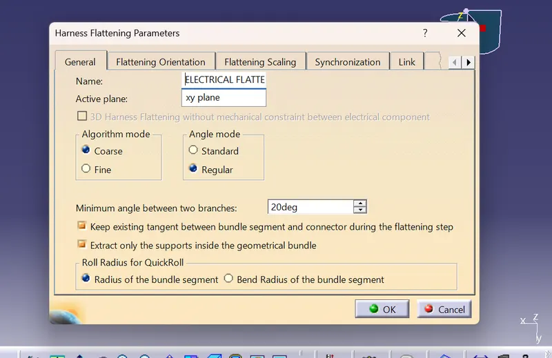
- we need to provide the name for the flattenings and the active plane that the flattening should be done
- the minimum angle should be kept at approx 20 Degrees
- The tangent (vector position )for the bundles should be adopt from the geometrical bundle of the wiring harness assembly cat product file
- We need to check the Extract the supports only from the geometrical bundle so that no background data is allowed for flattening in the workbench
- Roll radius of the qickball or for the roll feature is obtained from the radius of the bundle segment
Setting 02:
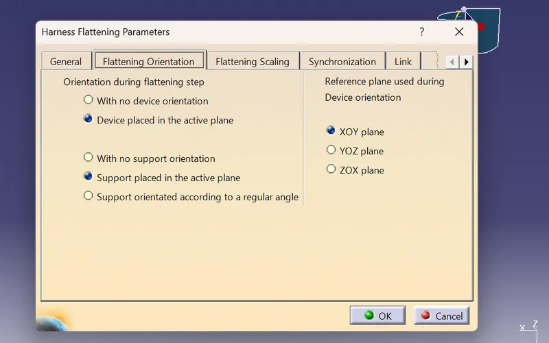
These are the parameters which are adjusted by the catia automatically so continue without making any considerable changes in the flettening orientation settings
Setting 03:
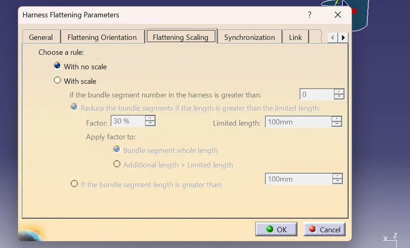
The flattening scaling is very useful as it would like to fake the dimension of the product in the flattening workbench as adjusted as the wiring harness product components are very long so just dont alter anything any continue
Setting 04:
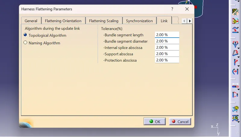
These are the parameters which are adjusted by the catia automatically so continue without making any considerable changes in the link settings
Setting 05:
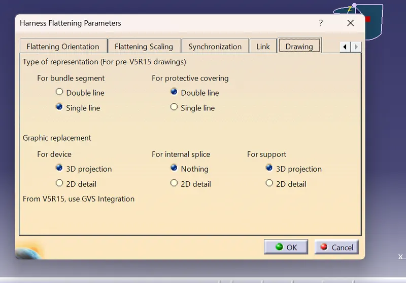
The bundle segment representation either in single line / double line
For rotective covering single line / double line
This the setting which will help us to get the better output in the drawing sheet adopted from the flattening
Aim : To create the wiring harness flattening sheet for the project 02 cat product
First we need to craete anew product and apply the flattening settings required and store in a desired location
Now open the project 02 cat product and save this product to the same desired location where the flattening cat product is saved so that when any changes are ,ade in the challenge 04 cat product those changes can be easily adopted to the flattening product by using the synchronize feature in the flattening workbench 
Now open the two products vertcally side by side and click on the flattening product < Extract command < geometrical bundle of theproject 02
Now use
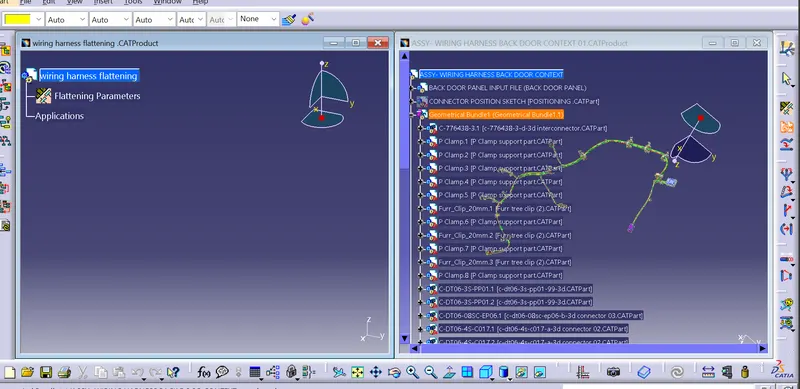
Now use the flatten command to make the bundle looks flat.and used properly for the drawing sheet preparation
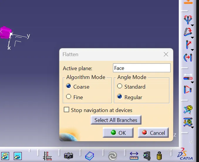
Select any of the flat face for the flatteningof the harness bundles and select all the bundles make sure all the bundles are highlighted for flattening or not then click ok then the wiring harness bundles got flatten
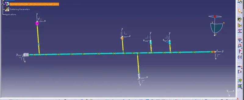
So the harness bundles are flatten then crate a flattening drawing of the wiring harness bundles
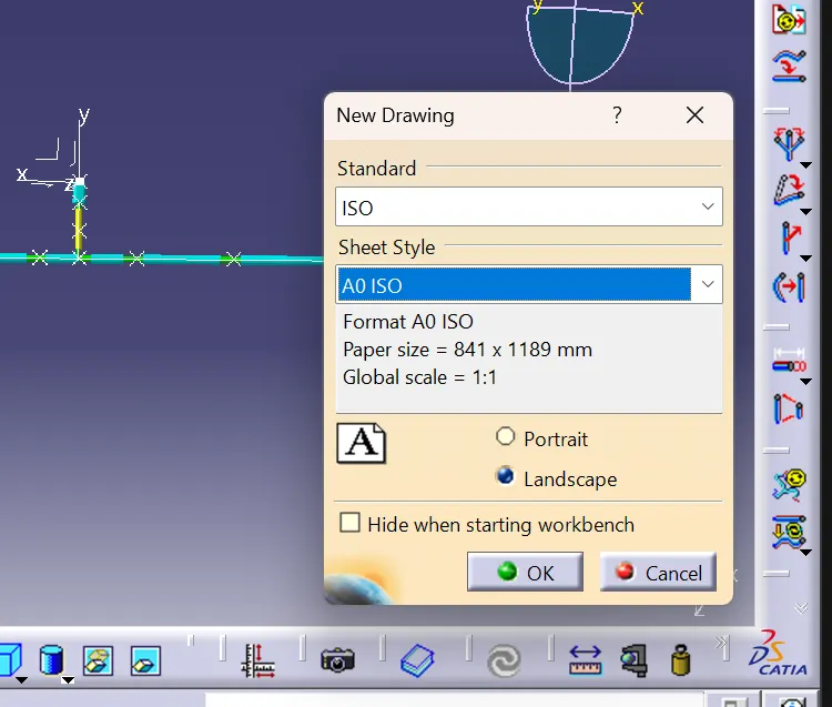
Now select the 3Dview in the drafting workbench and select any of the face to adopt the flattening file into the drafting workbench
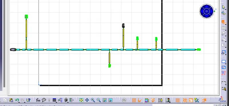
Now adjust the properties of the drafting worksheet and the single line represents trhe bundle segment and the double ;line represents the protective covering
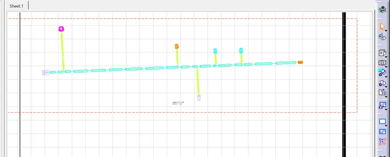
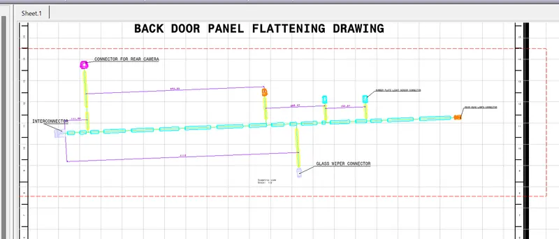
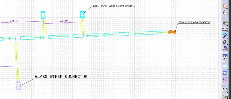
The front view of the hartness bundle flattening drawing is
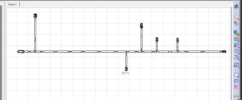
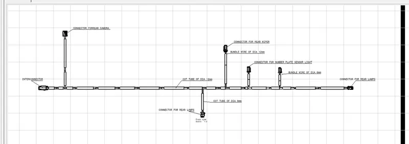
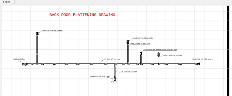
So the flattening drawing sheet is completed
Conclusion:
So the wiring harness for the rear door panel is roued by following the harness design rules and consideration and flattening of the wiring harness is done and the flattening drawing sheet is prepared
And the cad product files of the assembly and the flatteing drawing and the assembly files are uploded using the browse option below
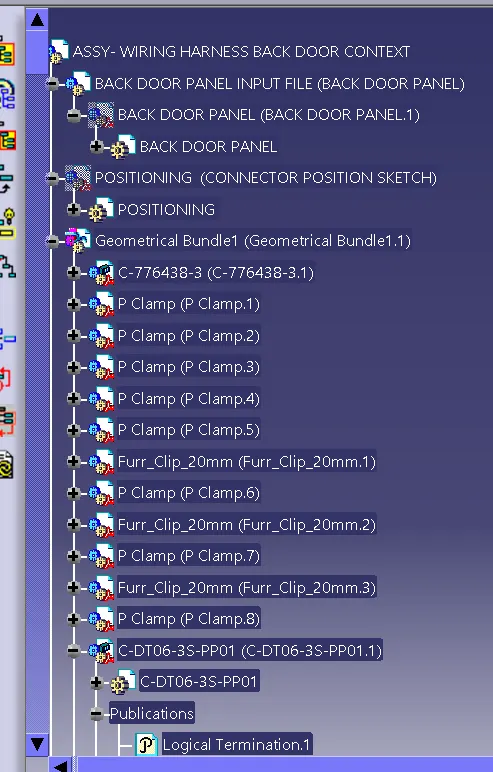
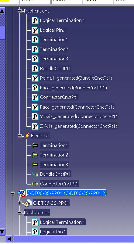
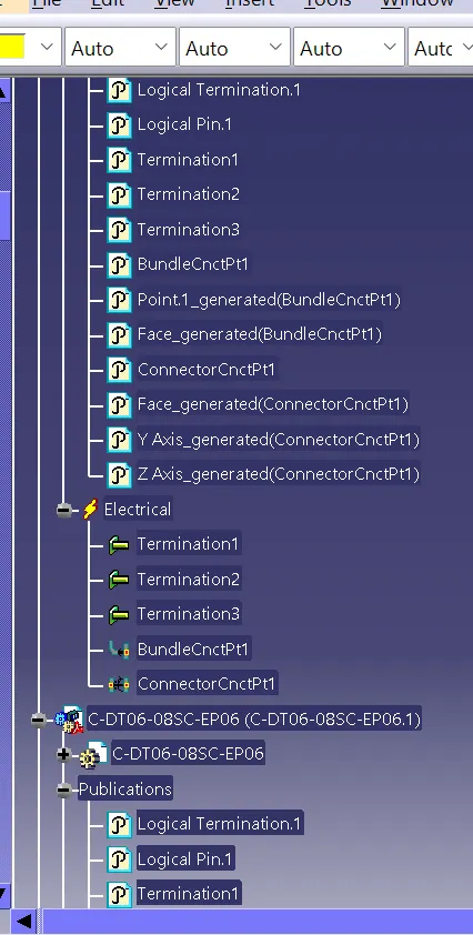
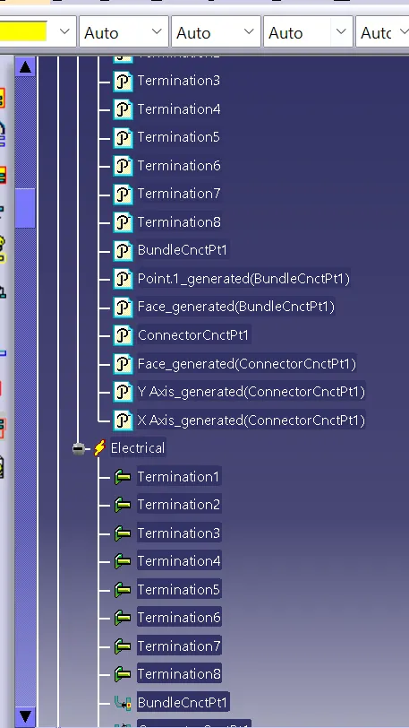
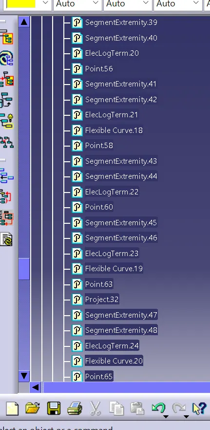
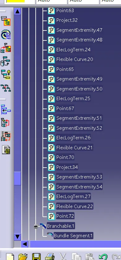
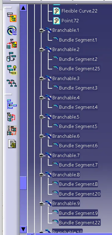
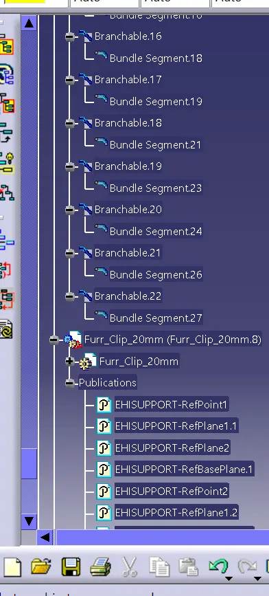
Tree structure