Project 2
1.Isolated buck converter:
The isolated buck converter is made using a transformer connected between the switch and the diode.
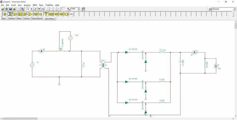
The circuit for forward converter is shown above.THe mosfet is connected with the primary of the transformer and the secondary of the transformer is connected with the diode.The mosfet shown is pmos which has lower drain to source resistance and the necessary voltage conditions.
The output voltage of the circuit is given by,
Vo=(N2/N1)*D*Vs
Assume N2/N1=1,Vs=45-60,V0=3V
D=V0/Vs
=3/45
=0.06
D=3/60
=0.05
The load resistance can be found from the average current in the inductor is given by,
Il=Vo/R
R=3/100
=0.03 ohm
The inductor value is given by,
L=(Vo/fs`Delta`Il)(1-D)
=(3/200k*10)(1-0.06)
=1.41uH
The capacitor value is given by,
C=(1-D)/8Lfs^2(`Delta`Vo/Vo)
=(1-0.06)/8*1.41u*200k*200k*0.1
=0.2uF
The simulation of the converter will result in,
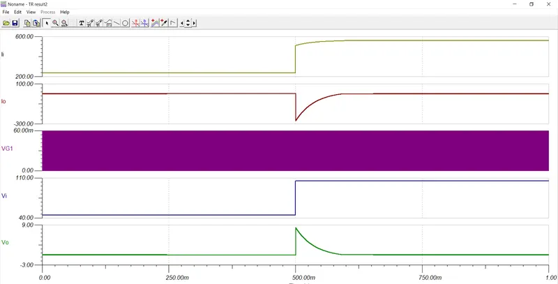
The input voltage varies from 40V to 60 V.When the voltage is 40,the output voltage is near about 2V.The output current is about 100A.After half of the time the input voltage changes and the output voltage and the current increases acoording to the value.
The multiphase scheme is implemented by connecting the diodes in a parallel manner to increase the efficiency.