Project 2
Route the Wiring harness on Given car body and Prepare flatten view drawing in CATIA V5. Application of all Packaging rules, Industry best practices studied in this course shall be demonstrated in design. Apply Protection coverings as required.
Answer:
Back Door Harness Assembly requires the following connection connectors
- Inter connection Connector – 1
- Top mounted stop light connector – 1
- Defogger connectors – 2
- Brake Light Assembly Connections – 2(LH and RH)
- Number plate Light Connections – 1
- Wiper motor Connection - 1
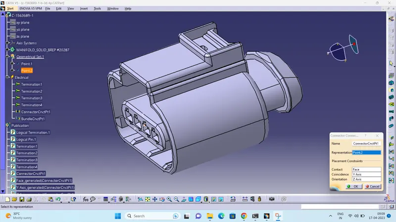
1.C-1563689-1 used as Brake Light and wiper motor connector.
- Create midpoint on the contact face which will be normal to wire bunddle insertion.
- Craete Axis System with respect to the point which we have created and defining the axis direction.
Switch to 'Electric Part Design'
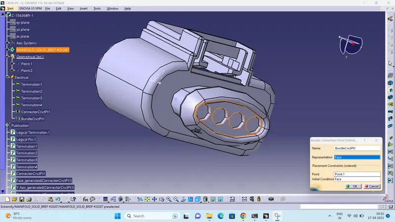
- Define the part as connector in catia, give no. of termination as 4 because we have 4 entry points for wire.
- Bundle connection point:
- Bundle connection point:
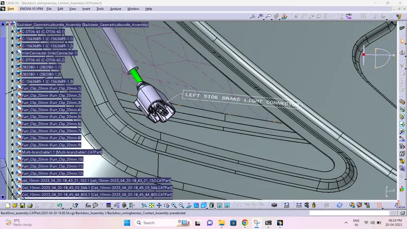
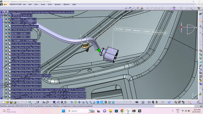
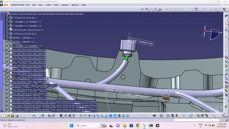
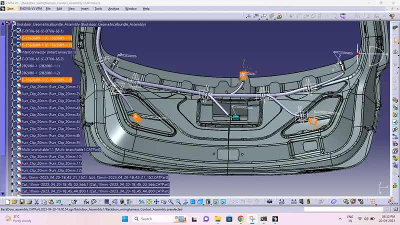
2. 282080-1 used as defogger connector
- Create midpoint on the contact face which will be normal to wire bunddle insertion.
- Craete Axis System with respect to the point which we have created and defining the axis direction.
Switch to 'Electric Part Design'
- Define the part as connector in catia, give no. of termination as 2 because we have 2 entry points for wire.
- Define Bundle connection point
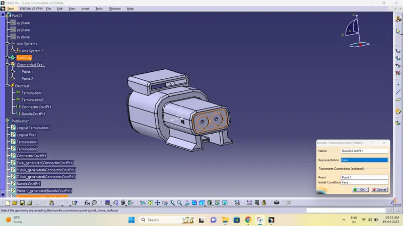
- Define connector connection point
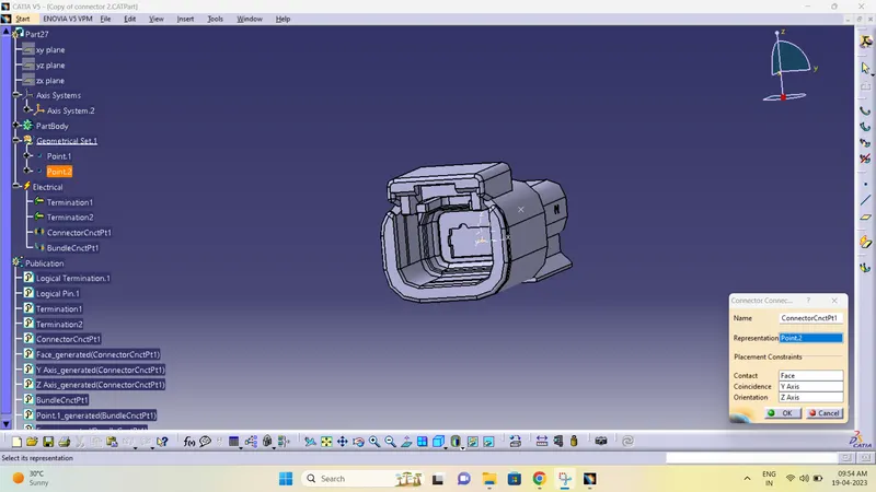
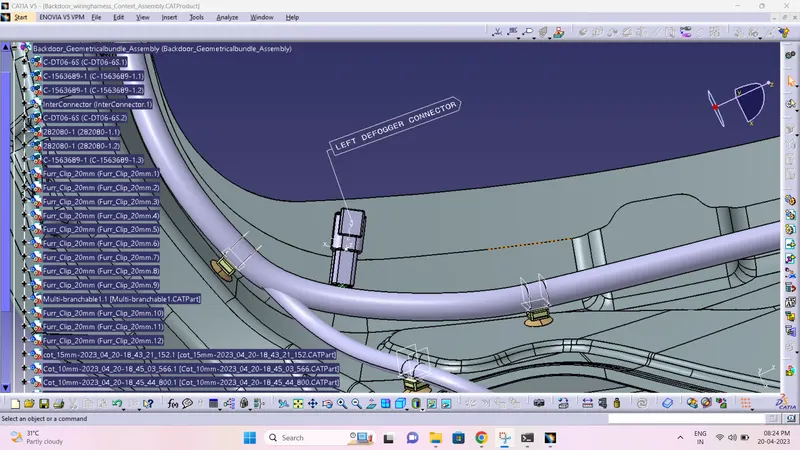
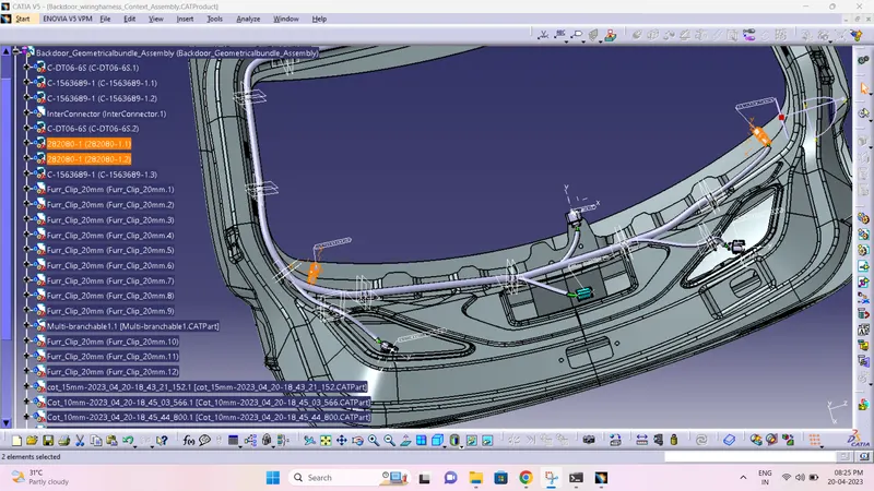
3.776438-4 used as Interconnector
- Create midpoint on the contact face which will be normal to wire bunddle insertion.
- Craete Axis System with respect to the point which we have created and defining the axis direction .
Switch to 'Electric Part Design'
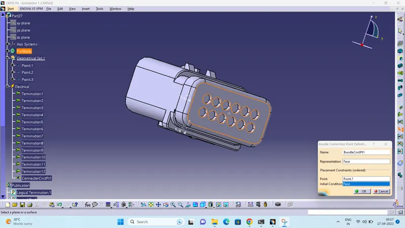
- Define the part as connector in catia, give no. of termination as 12 because we have 12 entry points for wire.
- Define Bundle connection point:
- Define connector connection point
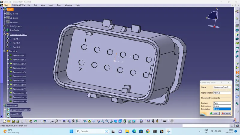
- create cavity connection axis system
- create cavity connection point
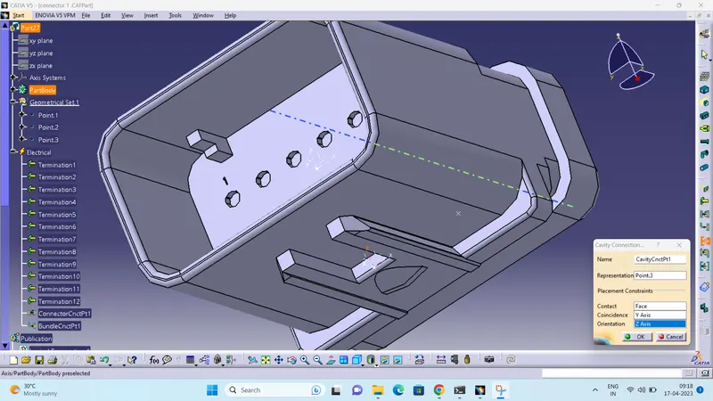
4. Tyco 85229-1 :
- Create midpoint
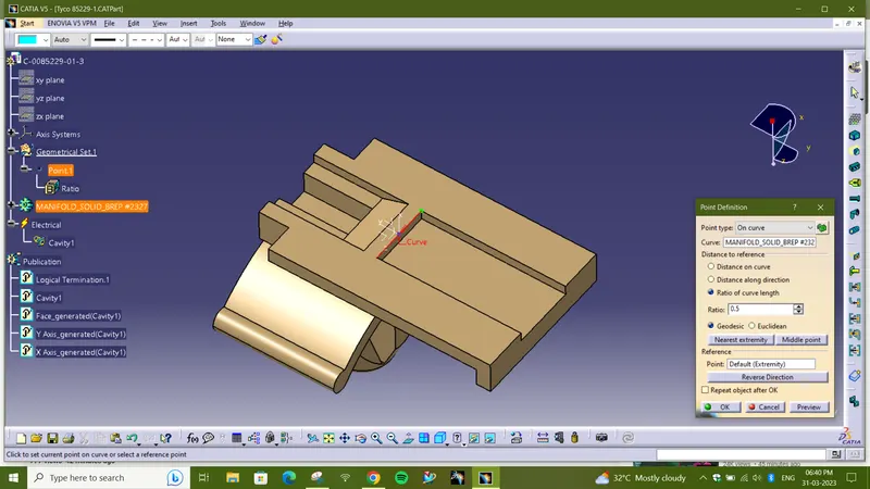
- create cavity connection point
- create cavity connection axis system and orientation should be same as in connector
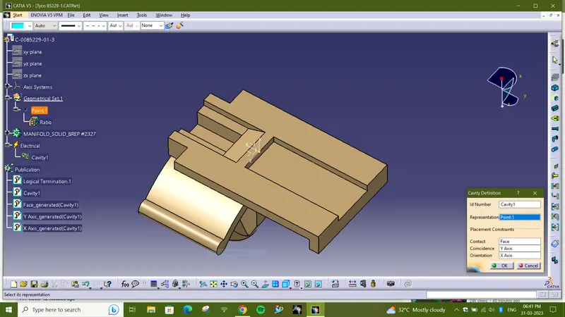
- Switch to Electric part design and define part as Mounting Equipment
- Define cavity connection point
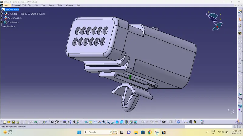
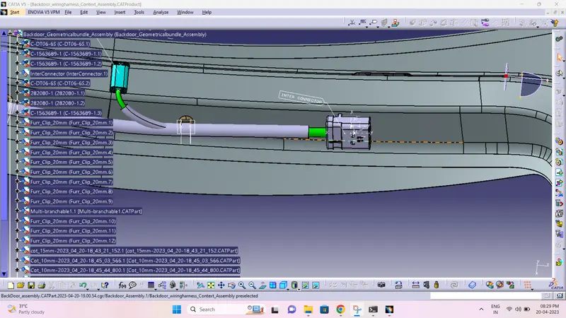
5.DT06-6S used as NAME PLATE LIGHT CONNECTOR and HIGH MOUNT STOP LIGHT CONNECTOR
- Create midpoint on the contact face which will be normal to wire bunddle insertion.
- Craete Axis System with respect to the point which we have created and defining the axis direction .
Switch to 'Electric Part Design'
- Define the part as connector in catia, give no. of termination as 6 because we have 6 entry points for wire.
- Define Bundle connection point:
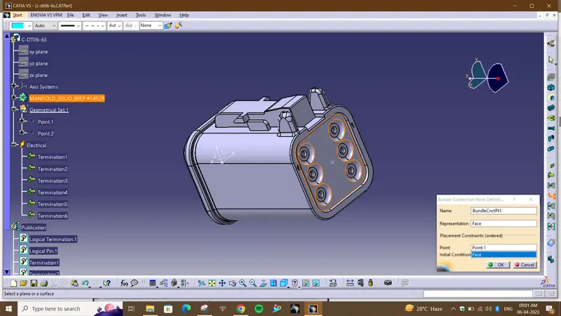
- Define connector connection point
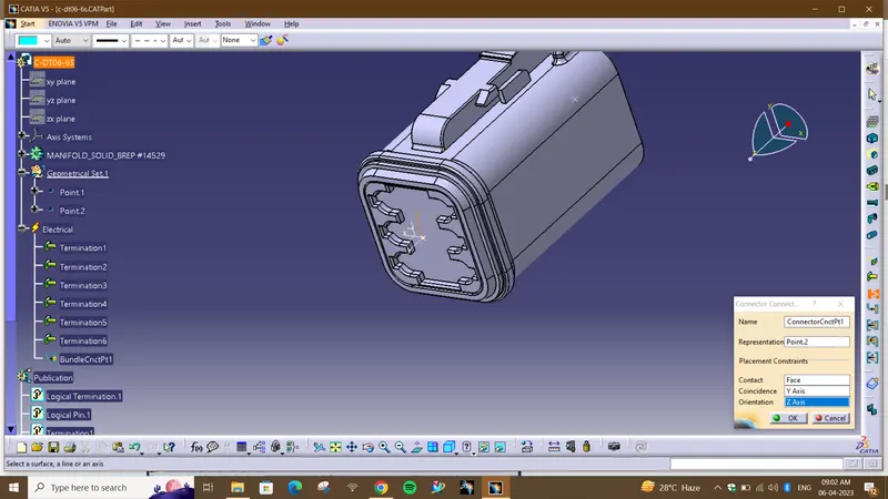
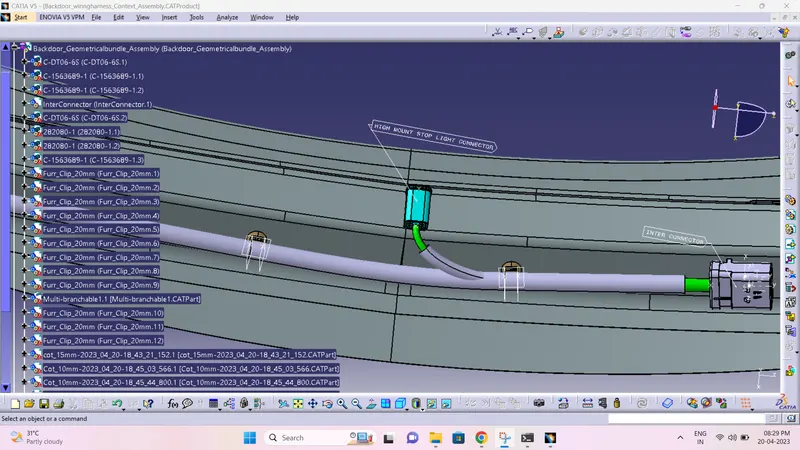
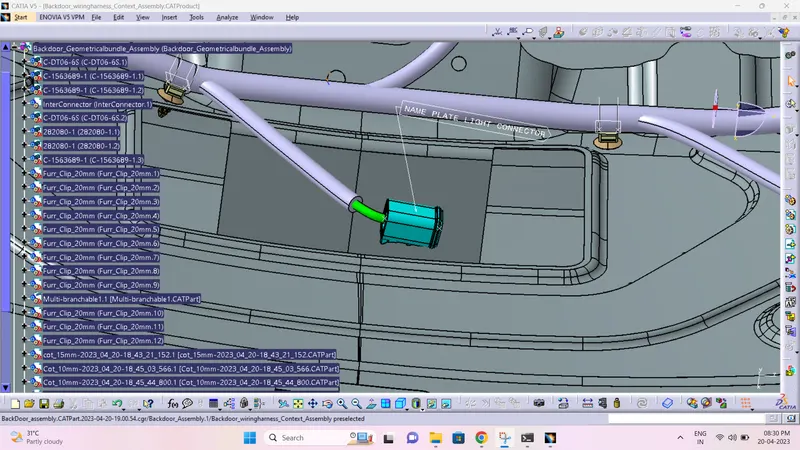
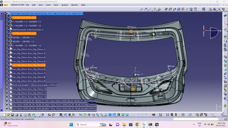
Furr tree clip:
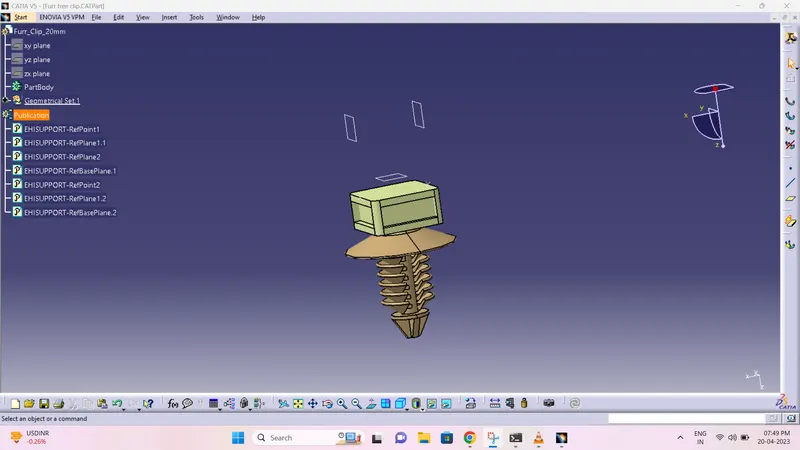
HARNESS CONNECTIVITY CHECK
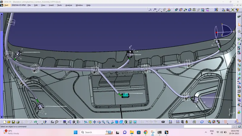
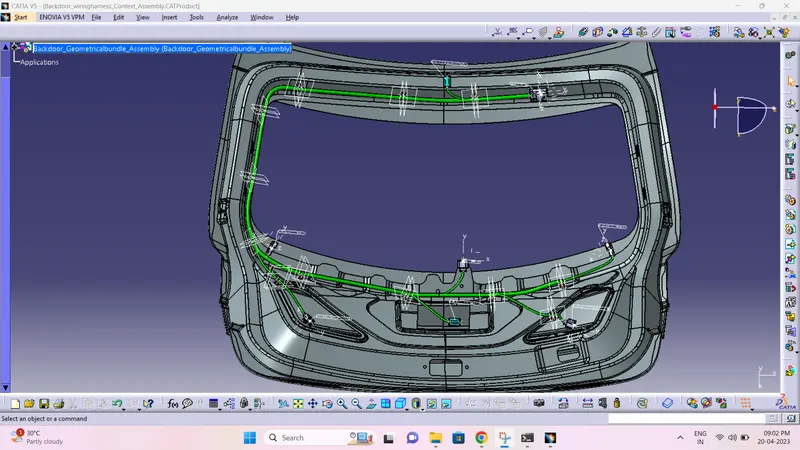
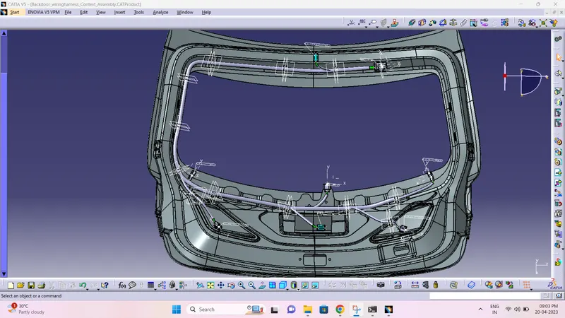
After all the connectors are defined, the workbench was switched to Electrical Harness Assembly where Geometrical Bundle was activated. All the connectors were routed using the Multi-Branchable Document command.
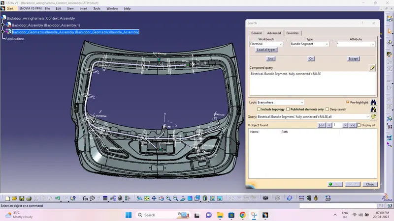
- Now in this step, we have to check bundle continuity.
- So for that, go in Edit>Search>Workbench-Electrical>Type-Bundle segment>Attribute-fully connected.
- We will get one window, in that selecting True option will show all the connected bundle segments while selecting False option will show all the non-connected bundle segments.
- Now, we will check for True condition and search for result.
- All the bundle segments are showing connected.
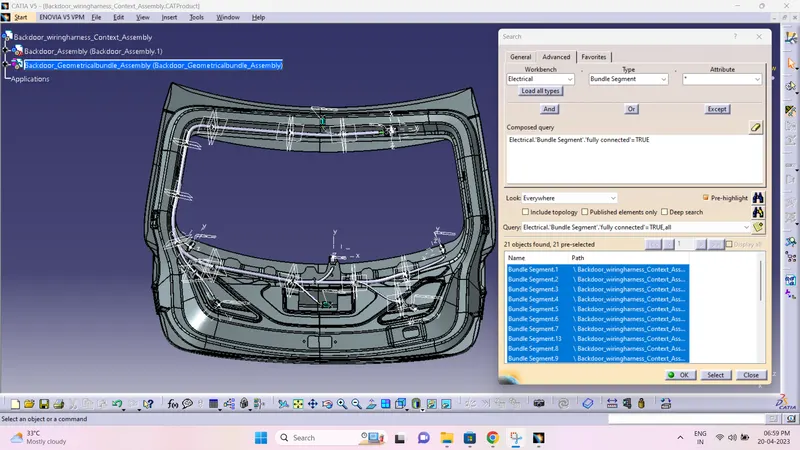
Checking for discontinuty
Harness Flattening Procedure:
- Harness flattening can be created from the Electrical Harness Flattening Workbench in CATIA V5.
- Create a new product file in the Electrical Harness Flattening workbench and rename it as of our requirement.
- Select the product file and define Flattening parameters to it. And we can rename it as of our requirement.
- Save the flattening product file in the save folder which is having all the other required documents.
- Create vertical windows with Harness assembly product and flattening product files.
- Using the Extract option, extract the harness assembly into the flattening product.
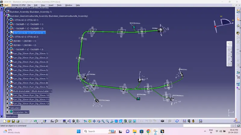
- Convert the extracted harness assembly into the flattened harness assembly by using the Flatten commend.
Before Flatenning
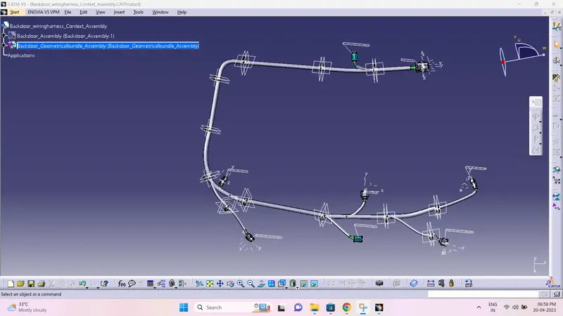
After Flatenning
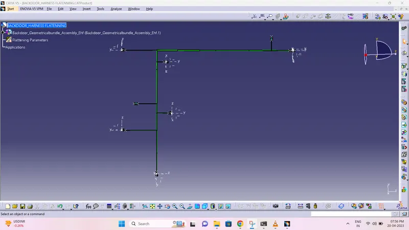
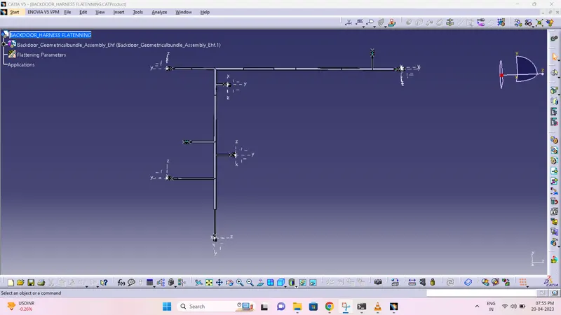
Create a Drawing File for the flattened harness product.
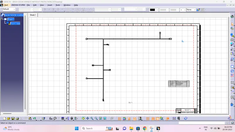
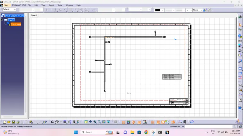
- First, we need to make sure that in the flatten parameter settings bundles and protective coverings have different graphical representation which are,
Bundle Segments - Double line representation
Protective coverings – Double line representation.
Drawing without protective covering:
Drawing with protective covering:
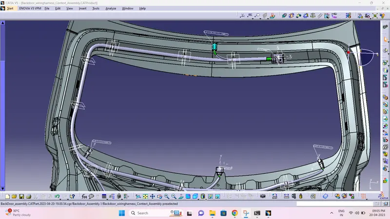
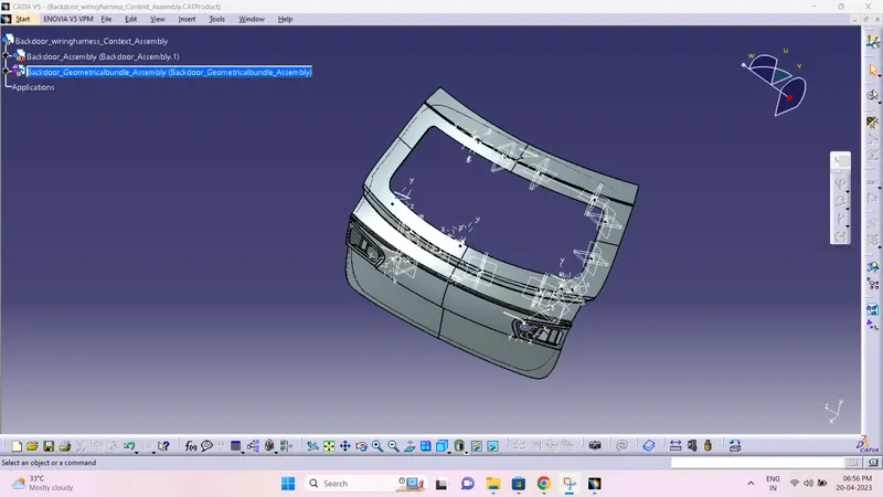
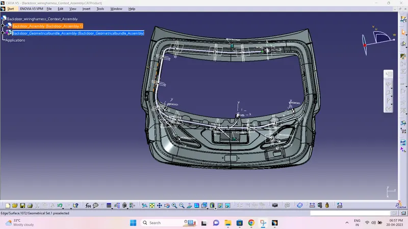
Final BACK DOOR HARNESS ASSEMBLY VIEWS:
NOTE:
For some reason annotations are showing (?) error after saving the file. I have consulted with the TSE and tried different methods in group session he told me to submit as it is and mention it in the report. But after clicking the connector they are turning to white colour. My self and conserned TSE sir are not able to find the error.
Conclusion
CAR back door wiring harness assembly has been successfully completed considering all the packaging rules and industry standards, Wiring harness flattening and Flattened view drawing preparations are also done using CATIA v5 software.