Project 2
ANSWER-
Introduction-
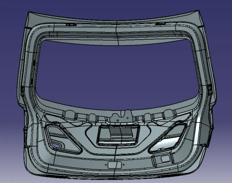
The trunk or boot of a car is the vehicle's main storage or cargo compartment it also have a hatch at the rear of the vehicle. It is also called a tailgate.These doors can be operated manually or electric powered. here we design the trunk or back door wire harness using the Catia.The Backdoor is an assembly of many parts such as inner panel, outer panel upper, outer panel lower and Reinforcement.Inner panel is attached to the outer panel using mastic sealant.
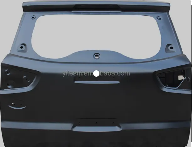
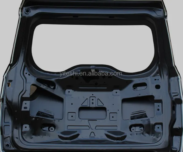
Door Wiring Harness-
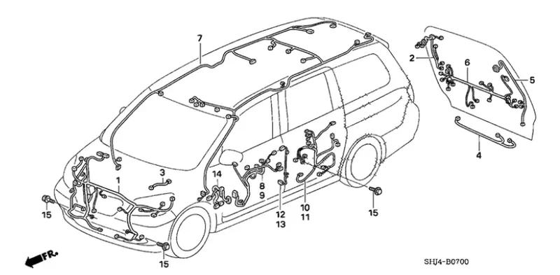
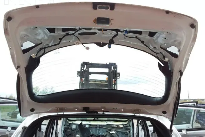
In the case of car doors, as the door of the automobiles opens and closes, the wires bend. If you use the car every day, the door will open and close many times. In case of Back door, the trunk could be open and close many times in daily life. Backdoor wiring harness mainly introduced to connect the brake lights, number plate lights, rear wiper motor, defogger connections. The harness routing should be maintained properly with all the supporting components like clips, clamps with proper protective covers, rubber grommets.
OBJECTIVE-
- Define all the mechanical connectors electrically and save it in the Catalogue.
- Place required Connecters on the Back door CAD data.
- Place Fir Tree clips at the required position by following the packaging rules.
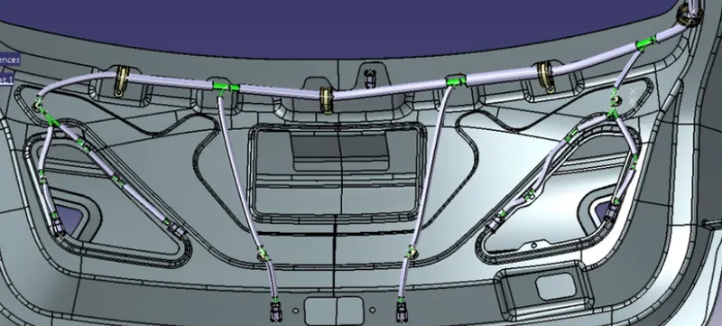
- Create the Wiring Harness Routing with all the electrically defined connectors and mounting equipments.
- Create branching points at required locations to create sub branches and connect to various connectors in the geometrical bundle.
- Apply Protection coverings as required.
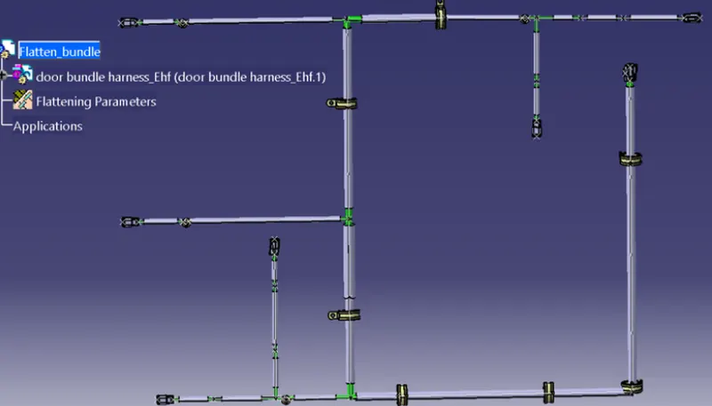
- Create Wiring harness flattening for the final geometrical bundle.
Back door assembly: The back door assembly has multiple connections for a tail lamp , indicators , number plate lamp and wiper mechanism. The inter connection is placed near to the opening and closing mechanism which is above hinge.
-
Obtain the 3D data for the connectors: If you have the 3D data for the connectors to be used in the wiring harness, import them into CATIA V5 as part files. If not, you can download connector models from reputable sources or create them using CATIA V5's built-in modeling tools.
-
Create a 3D wireframe of the wiring harness path: Use CATIA V5's wireframe modeling tools to create a 3D path along which the wiring harness will be routed. This path should follow the contours of the car body, avoiding obstacles and taking into consideration packaging rules and industry best practices, such as maintaining proper bend radii and avoiding sharp bends.
-
Route the wiring harness along the wireframe path: Use CATIA V5's routing module to route the wiring harness along the 3D wireframe path. This may involve creating individual segments of the wiring harness for different sections of the car body, such as the front, rear, or sides, and routing them accordingly.
-
Apply protection coverings: Based on industry best practices, apply protection coverings to the wiring harness to protect it from damage due to rubbing, abrasion, or other environmental factors. These coverings can be added as separate components in CATIA V5 or applied as surface treatments to the wiring harness geometry.
-
Flatten the view drawing: Once the wiring harness is fully routed and protected, create a flattened view drawing in CATIA V5 to document the final design. This drawing should include details such as the wire routing paths, connector locations, protection coverings, and any other relevant information.
-
Validate the design: Before finalizing the design, validate the wiring harness routing against packaging rules, industry best practices, and any other design requirements or constraints. Make any necessary adjustments to ensure that the design meets all specifications.
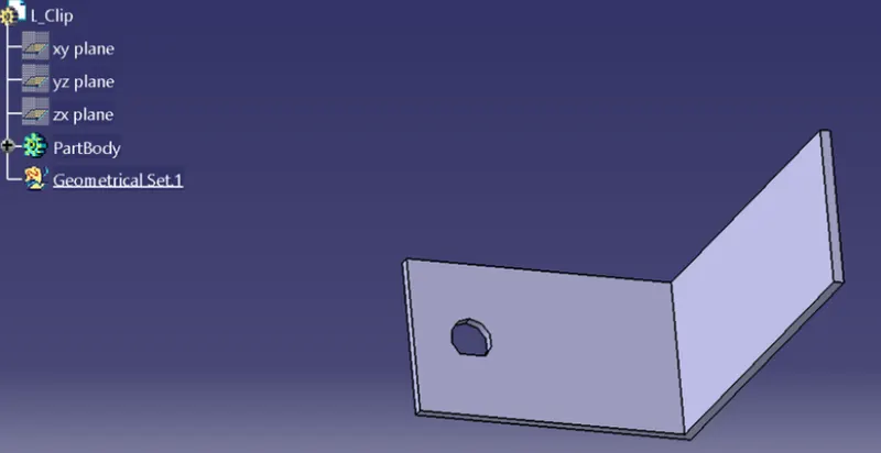
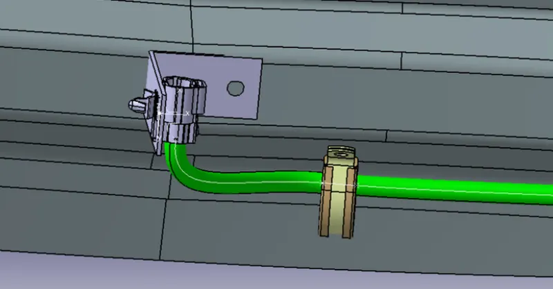
An L clamp is taken to mount the interconnector to the backdoor
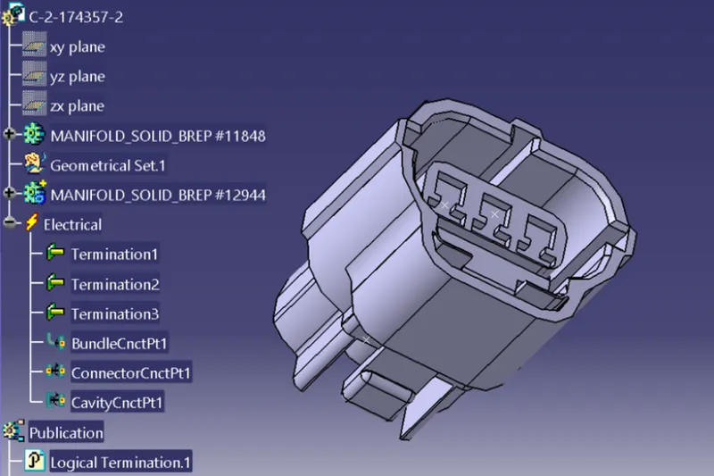
Interconnector we take C-2-174357-2 . The connector is mechanically and electrically defined to mount and connect the bundles.
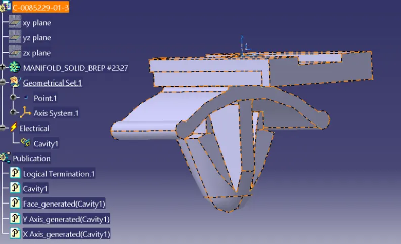
The mounting clip is electrically defined and connected to the connector through a clamp by means of electrical connection.
The Second connecter we choose is a C-DT06-2S for all other 7 connectors to the components .These are electrically defined.
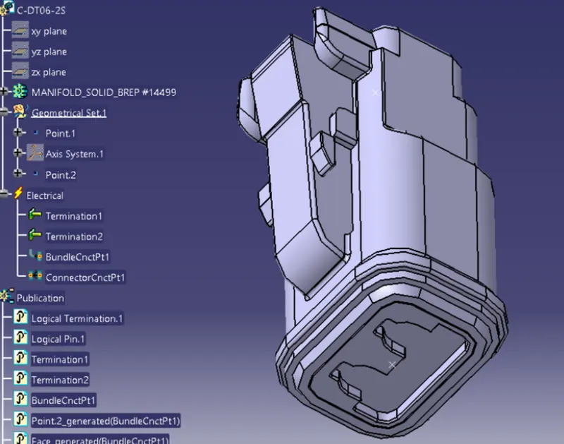
We select 3 supporting elements inorder support the wiring throughout the routing . These are P clamp , U clamp , Furr tree clip. These are all defined as an supporting part in catia v5.
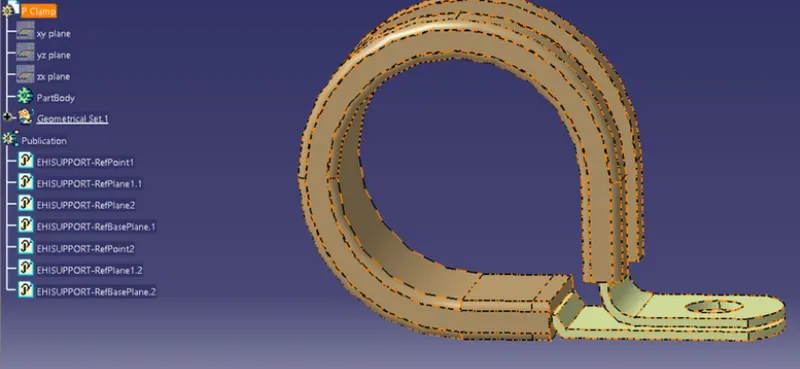
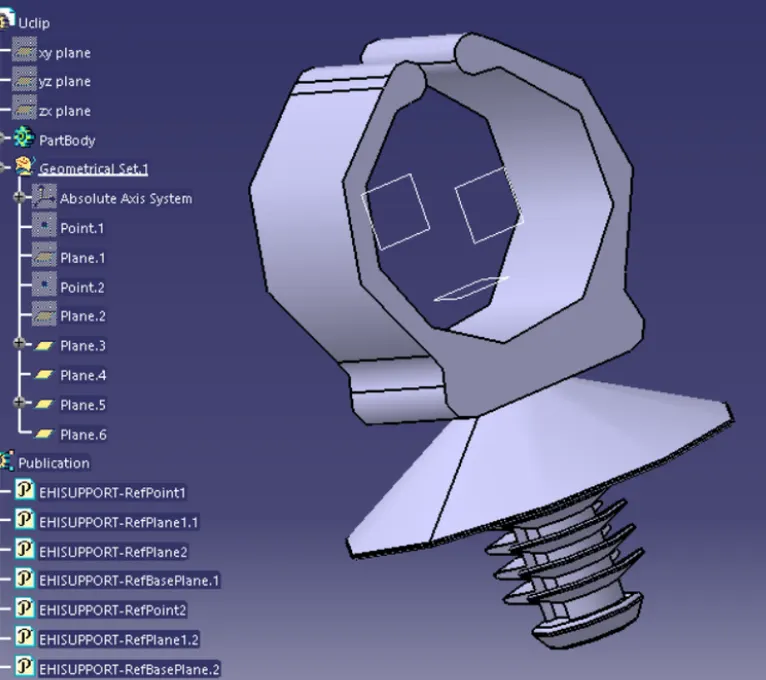
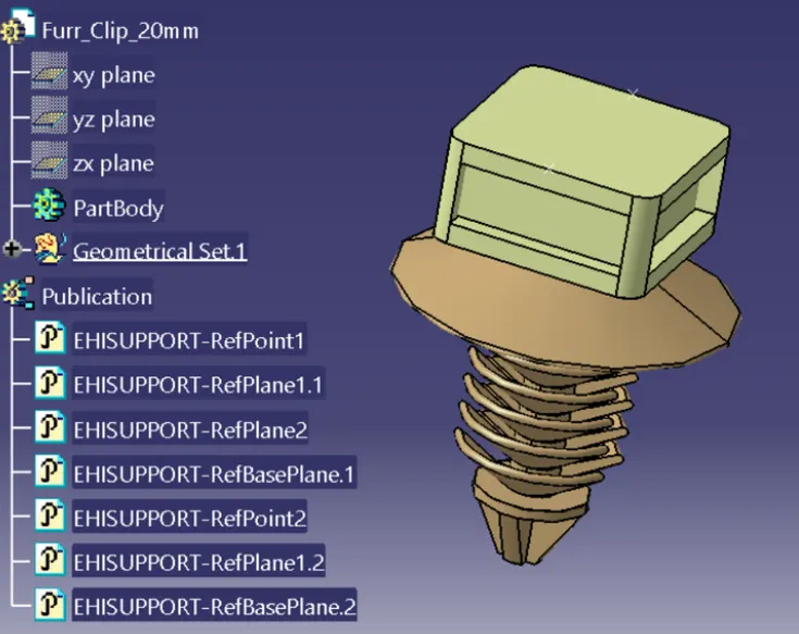
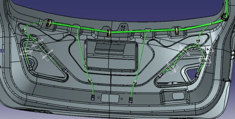
Now the connectors and supporting parts are placed in the right places with the help of assembly workbench move tools as shown below.
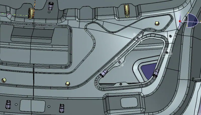
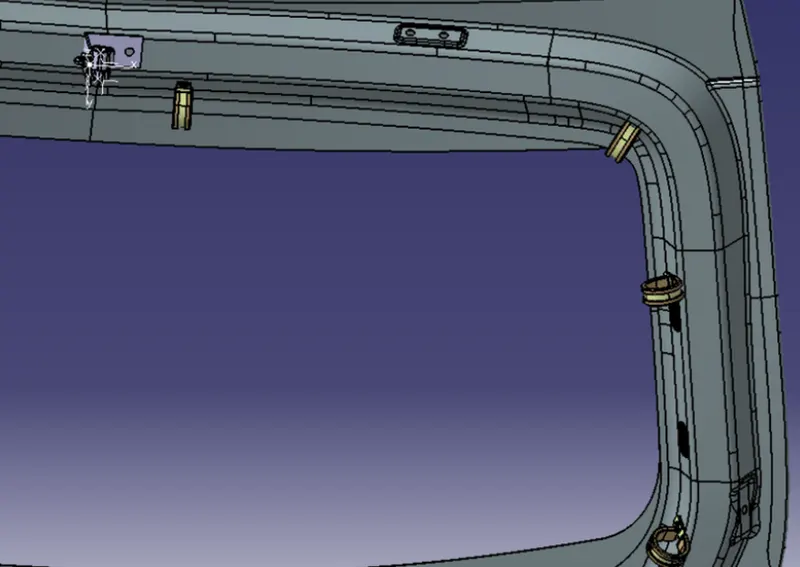
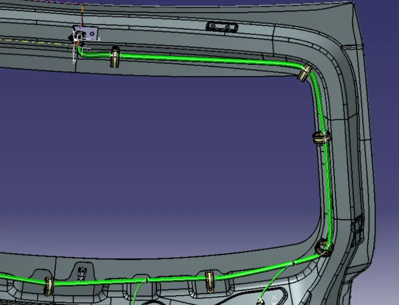
Once the components are in place we start the routing from the interconnector.
CONCLUSION:
Routing of the wiring harness for the car backdoor assembly has done. Applied all the packaging rules while routing the wiring harness, implemented industry best practices in the harness design. Also, provided details like clearance, clipping selection, harness fixing requirements, harness continuity in order to design the harness.