Project
AIM:
To Prepare a Technical report for BAJA All Terrain Vehical ATV Model without using look up tabel and using look up table
OBEJECTIVE:
Carry out the system level Simulation of an BAJA All Terrain Vehical and prepare the technical report explaining the model properties of without using look up table and using look up table and comments the results.
Model:
- BAJA ATV Model without Dashboard.
- BAJA ATV Model with Dashboard.
- BAJA ATV Model with CVT Ratio as RPM.
- BAJA ATV Model - Data Extraction.
- BAJA ATV Model with Mapped lookup Table without Dashboard.
- BAJA ATV Model with Mapped Lookup Table with Dashboard.
EXPLANATION:
BAJA ALL TERRAIN VEHICAL (ATV) MODEL:
All Terrain Vehicles (ATV) are among the most usefull land vehicle ever invented. Desigined to combat the hazards of different kinds of terrain, they can be used in almost every worksite there is. Not only do this make traveling easier for drivers, they are also safe to use when transporting loads or cargo, Suspension and chasis play a vital role in the strucatural performence of an off-road vehical.
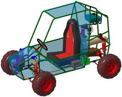
COMPONENTS OF A BAJA ALL TERRAIN VEHICAL (ATV):
The Main components are using in BAJA All Terrain Vehical (ATV) are given below:
Continously Variable Transmission (CVT):
- A continuously variable transmission (CVT) is an automatic transmission that can change seamlessly through a continuous range of gear ratios.
- This contrasts with other transmissions that provide a limited number of gear ratios in fixed steps.
- The flexibility of a CVT with suitable control may allow the engine to operate at a constant RPM while the vehicle moves at varying speeds.
- The most common type of CVT uses two pulleys connected by a belt or chain.
- CVTs are used in automobiles, tractors, and earthmoving equipment.
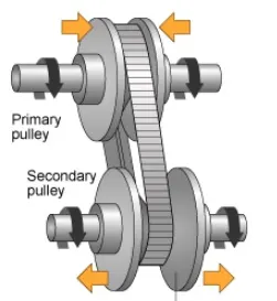
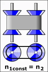
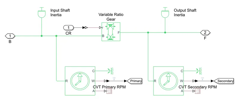
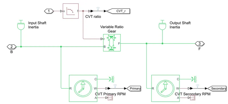
CVT:- This subsystem is created using following blocks
- Inertia
- Ideal Rotational Motion Sensor
- Mechanical rotational Reference
- PS- simulink converter
- Goto
- PS terminator
- Variable Ratio Transmission
The CVT subsystem is shown below
Common Block Used:-
- Signal Builder
- Goto
- From
- Simulink PS Converter
- Solver Configuration
- Mechanical Rotional Reference
- Scope
- Simple Gear
- Generic Engine
Common Subsystem Created are :-
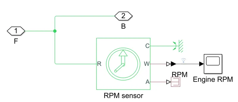
Engine Sensor:- It is a subsystem created using following blocks.
- Ideal Rotational Motion Sensor
- Mechanical rotational Reference
- PS-simulink converter
- Scope
- PS terminator
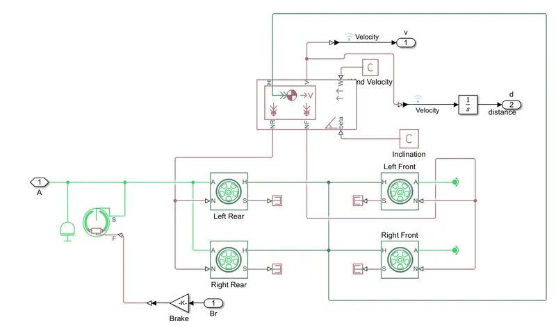
Vechicle Body:- This subsystem is created using blocks as given below
- Inertia
- Double Shoe Brake
- Gain
- Tire
- PS terminator
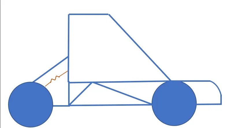
- Vechicle Body
- PS constant
- PS-simulink converter
- Integrator
- Rotational Free End
BAJA ATV Model:-
BAJA ATV Model without Dashboard:-
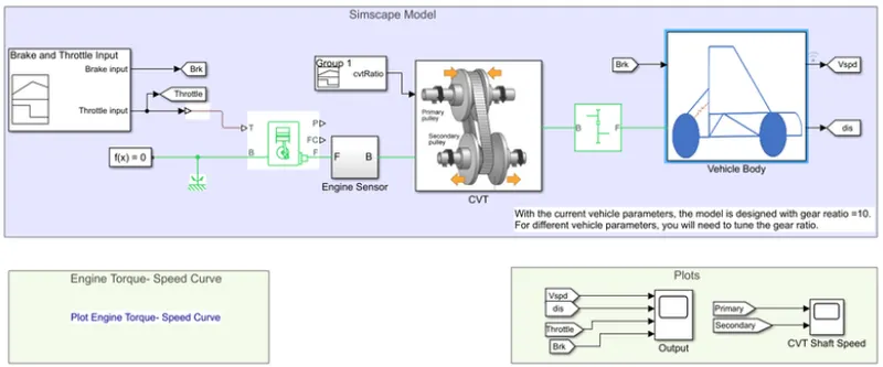
- Model:- The file name for this model is 'cvtmodel.slx'
Working:-
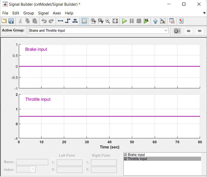
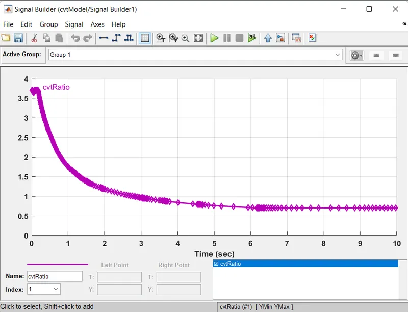
- The signal Builder block used for providing Brake input , Throttle input and CVT Gear ratio input.
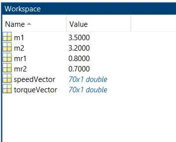
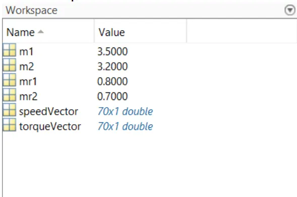
- The torque vector and speed vector input is provided from MATLAB Workspace.
- The Throttle input is given to the Engine where the engine parameter changes accordingly.
- The output from the Generic Engine is the pass through the Engine sensor block.
- The sensor block recorded the rpm of engine and forwards the output from engine
- The break input is given to the double shoe brake block via gain block.
- The output from brake block provided to tires.
- The vehicle body block provide velocity foe all tiers.
- It also provides output signal velocity and displacement using integrator.
Input Data:-
Signal Builder Block Input:-
Brake and Throttle Input:-
CVT Ratio:-
MATLAB Workspace:-
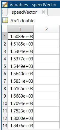
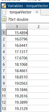
Gear Ratio is 10.
Result:-
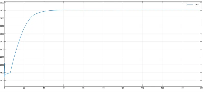
The simulation time is 200 seconds
Engine RPM:-
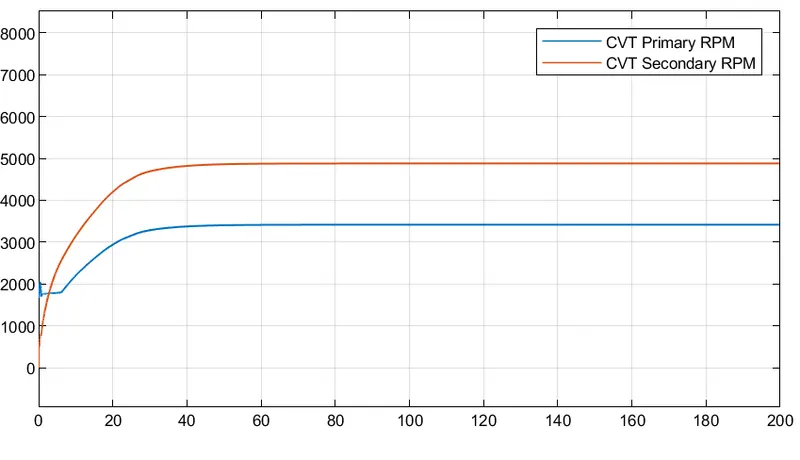
CVT Shaft Speed:-
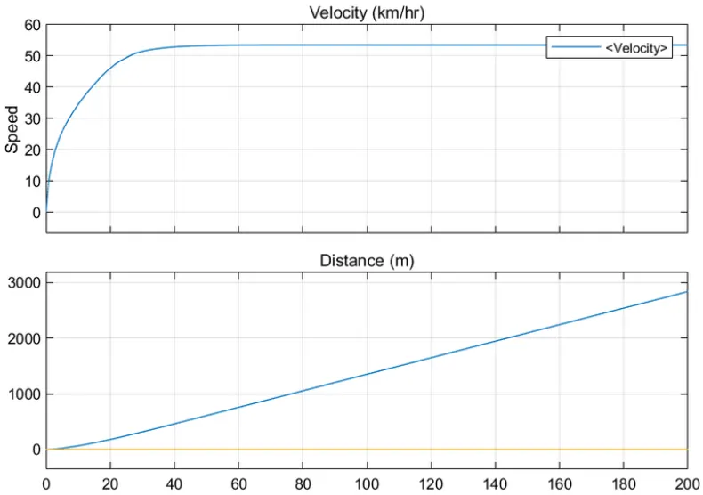
Velocity and Displacement:-
BAJA ATV Model with Dashboard:-
Model:-
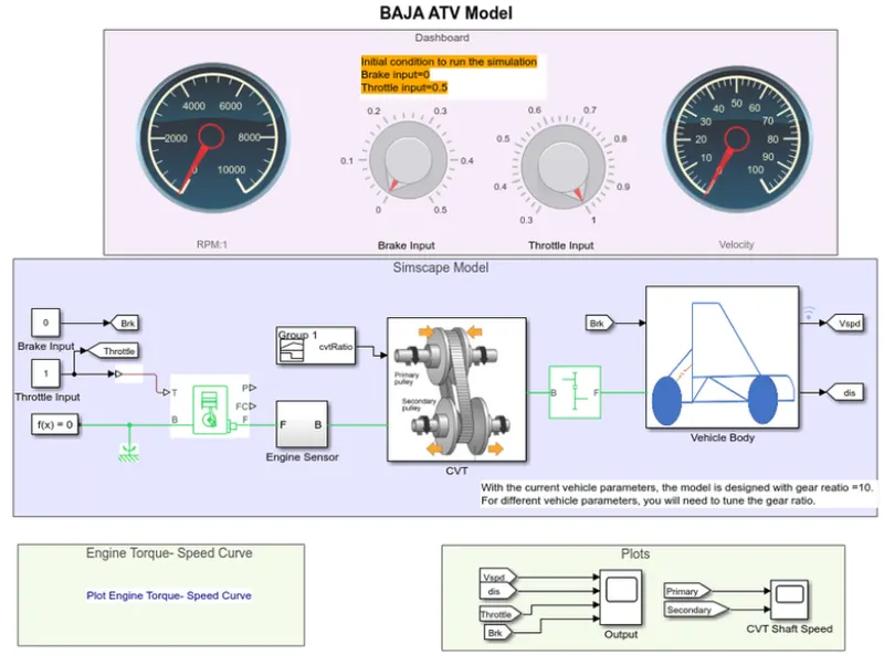
The file name for this model is 'cvtmodel_dashboard.slx'.
Blocks used:-
- Circular Gauge
- Knob
Working:-
The working oof BAJA ATV Model with dashboard. The only difference is here we can modify input i.e. throttle input and brake input during simulation using Knob.
Input Data:-
CVT Gear Ratio:-
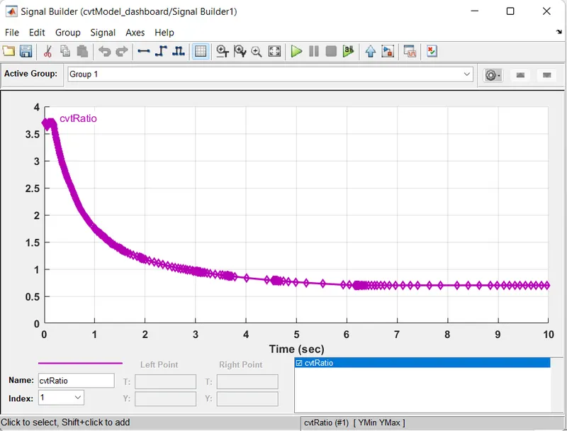
The CVT Gear Ratio is provided using Signal Builder Block.
Matlab Workspace:-
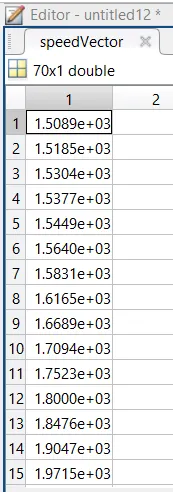
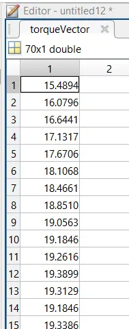
Gear Ratio is 10
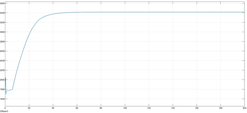
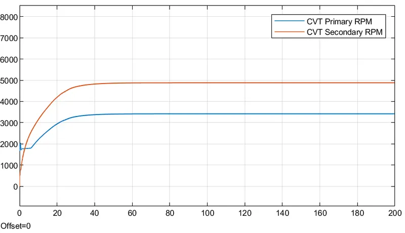
Case 1 Brake=0 and throttle=0.5
Engine RMP:-
CVT Shaft Speed:-
Velocity and Displacement:
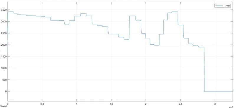
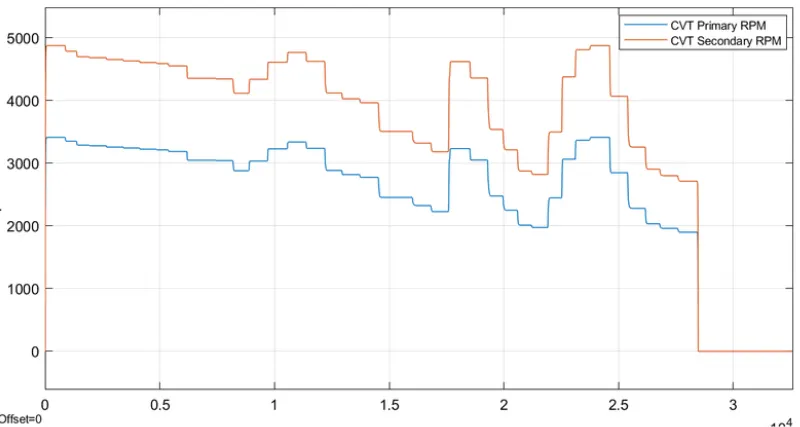
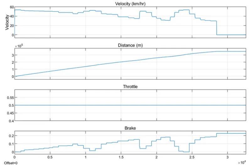
Case 2: Brake=Varying and Throttle=0.5
The simulation time is set in infinity for the case. As the Throttle value is constant,Brake value is varying. When the brake value exceeds 0.2, the RMP becomes 0. So the brake applied between 0 to 0.2.
Engine RPM:-
CVT Shast Speed:-
Velocity and Displacement:
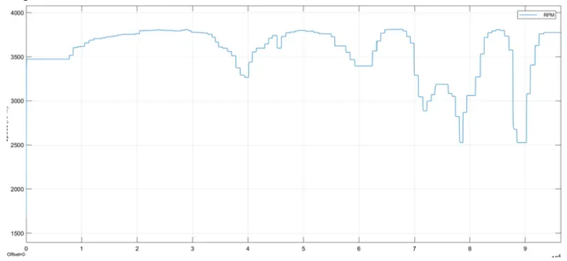
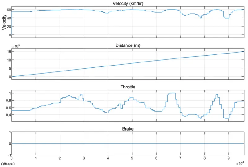
Case 3: Brake=0 and Throttle=Varying
The simulation time for this case is infinity
Engine RPM:
CVT Shaft Speed:
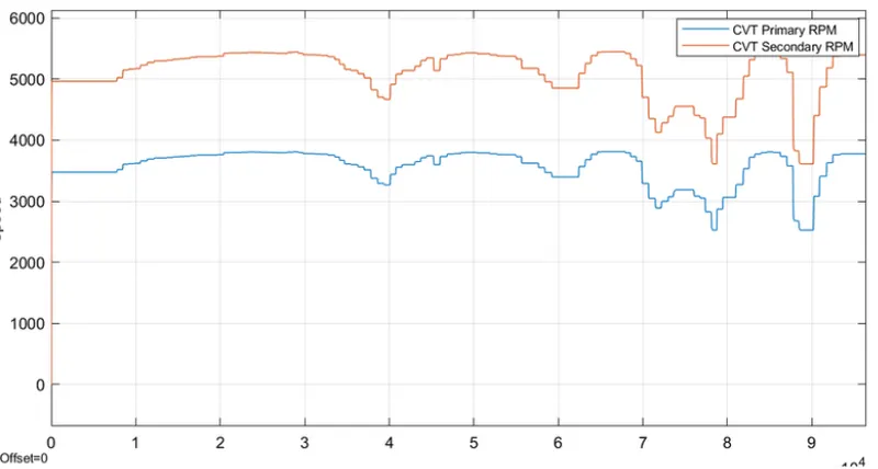
Velocity and Displacement:
BAJA ATV Model with CVT Ratio as RPM:
Model:
The file name for this model is 'cvtModel_cvtratio.slx'.
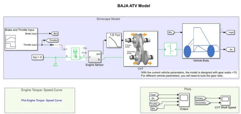
Block used:
1-D Lookup Table: This block maps inputs to an output value by looking up or interpolating a table of values you define with block parameters.
Working:-
The working of BAJA AATV Model without Dashboard. The difference here is the instead of signal builder input for CVT Gear Ratio here engine rpm is given as CVT Ratio using Lookup Table block.
Input Data:
Brake and Throttle Input:
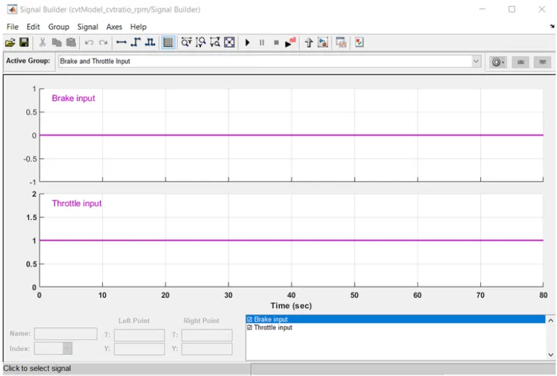
Lookup Table Input:
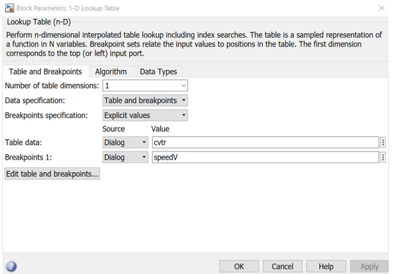
CVT Ratio is Given by the Engine RPM output provided by Generic engine.
Gear Ratio is 10.
Results:-
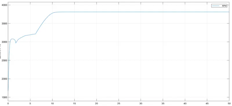
The simulation time is 50sec.
Engine RPM:
Here this output is also Input for CVT Gear ratio for CVT subsystem
CVT Shaft Speed:
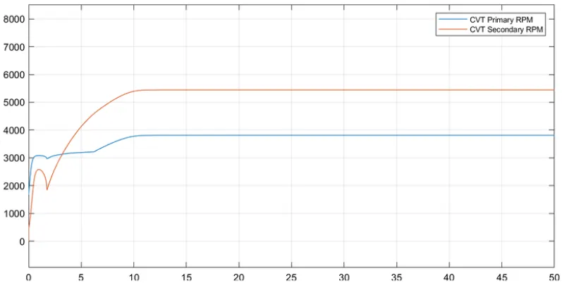
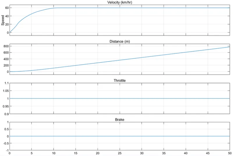
Output plots:-
BAJA ATV Model with data Extraction
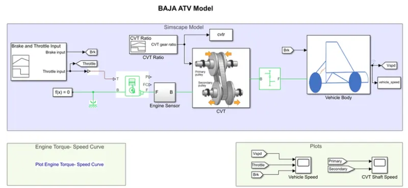
Model:
The filename for this model is 'cvtModel_data.slx'.
Working:
The working of BAJA ATV Model Dashboard. The only difference is here the output gets saved to Matlab workspace file using To workspace Block.
Input Data:-
Signal Builder:
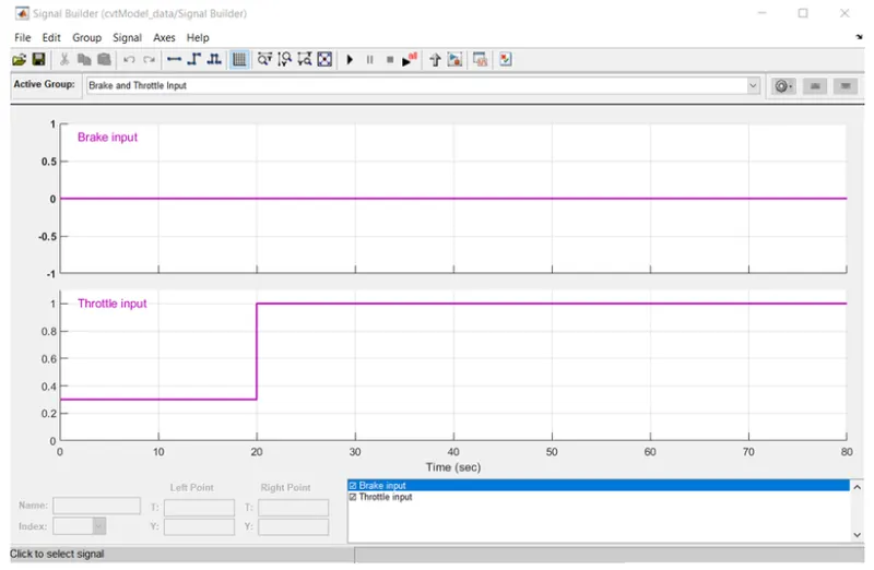
Brake and Throttle Inputs is
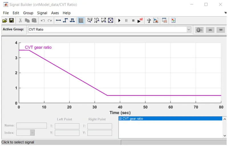
CVT Ratio:
Workspace:
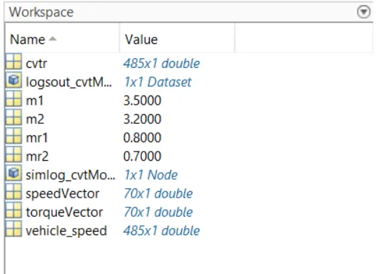
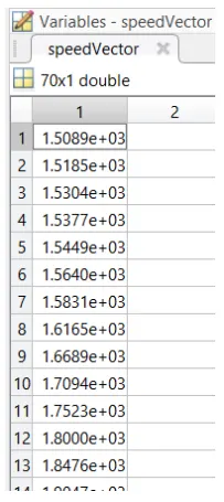
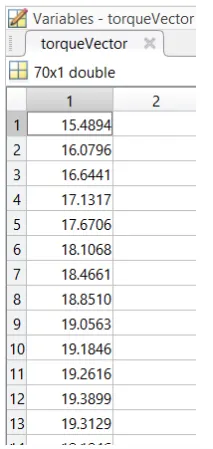
Gear Ratio is 12.
Result:
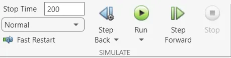
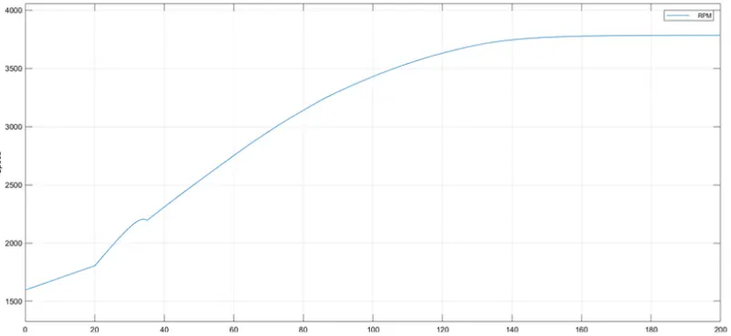
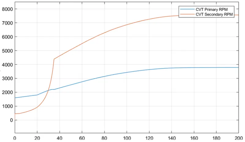
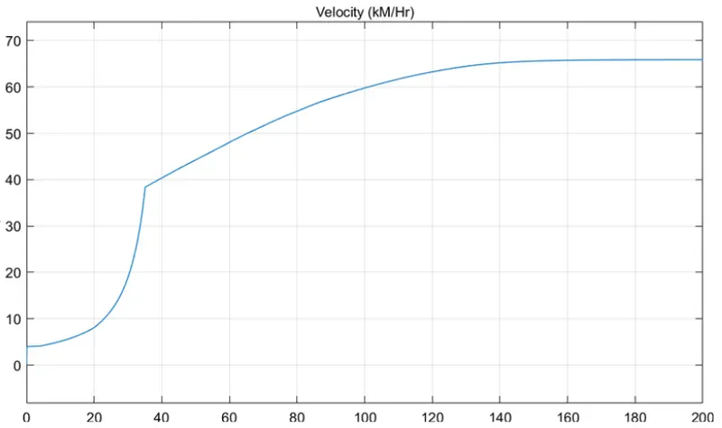
The simulation time for this model is 200sec
Engine RPM:-
CVT Shaft Speed:-
Velocity Speed:-
BAJA ATV Model with Mapped Lookup Table without Dashboard:-
Model:
The filename for this model is 'cvtModel_mapped.slx'.
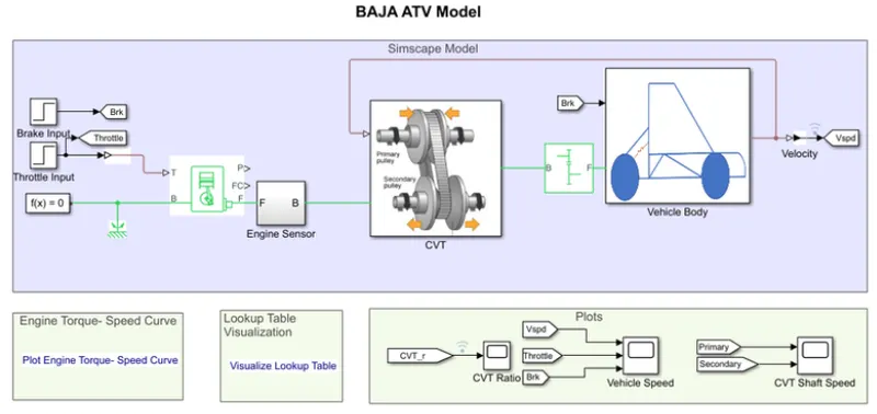
Blocks used:
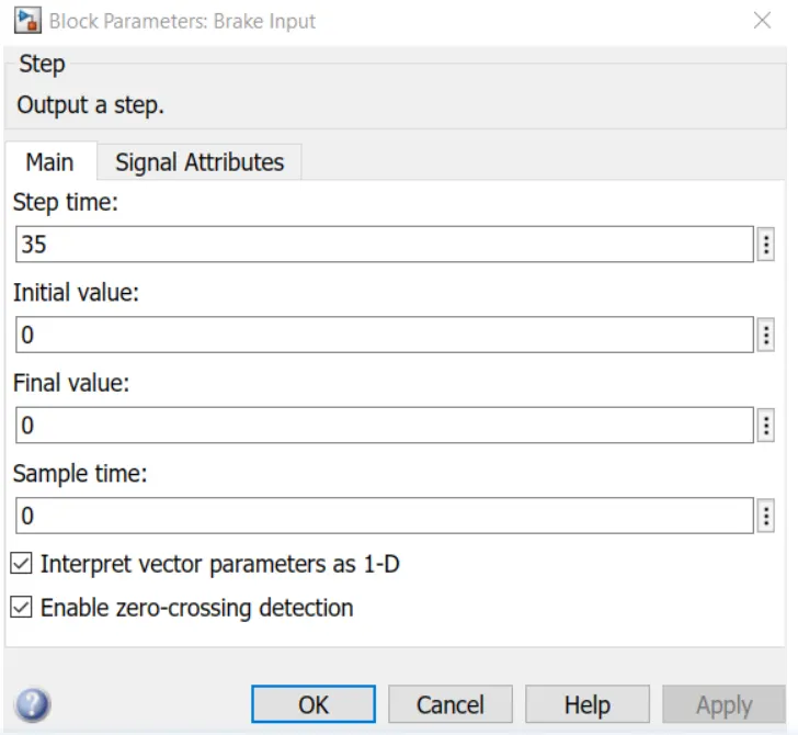
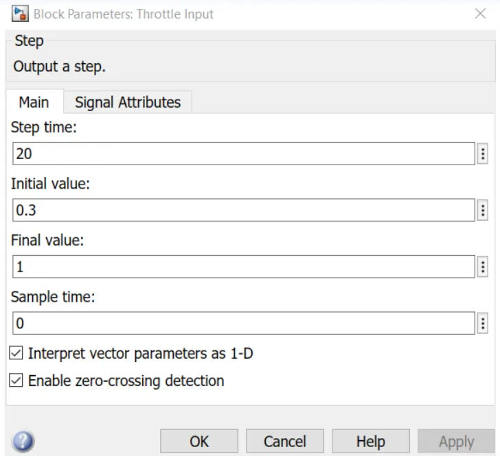
- Step:The Step block provides a step between two definable levels at a specified time.
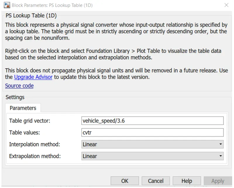
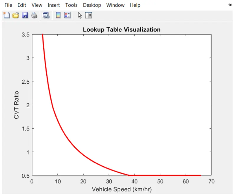
- PS Lookup Table: The PS Lookup table (1D) block approximation to some function f=f(x) given data vector x and f. Both the input and the output are physical signals.
CVT Sub System:-
Working:
The working of BAJA ATV Model without dashbord. The different is step input signal is used here. Also in CVT gear ratio. It needs to be loaded in the workspace using the file name Lookup Table_data.mat.
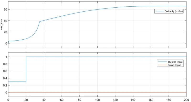
Brake Input:
Thorttle Input:
PS Lookup Table (1D):
Gear Ratio is 12
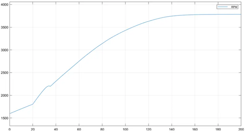
Engine RPM:
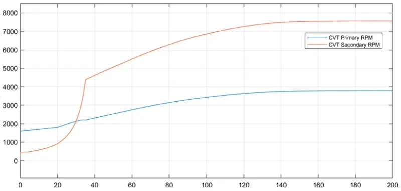
CVT Shaft speed:
Vehicle Speed:
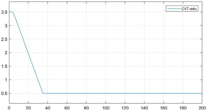
CVT Ratio:
BAJA ATV Model with Mapped Lookup Table with Dashboard
Model:
The filename for this model is 'cvtmodel_dashboard_mapped.slx'.
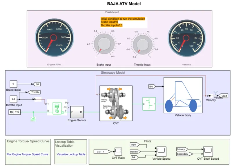
Working: The Dashboard is difference here is that the input provided by using Knob.
Gear Ratio is 12
Result:-
The simulation time for this model is infinity.
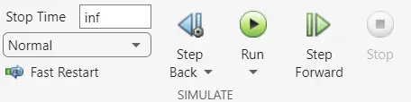
Dashboad Model Simulation OFF.
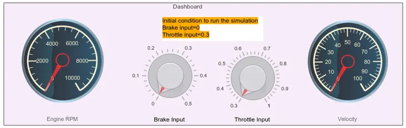
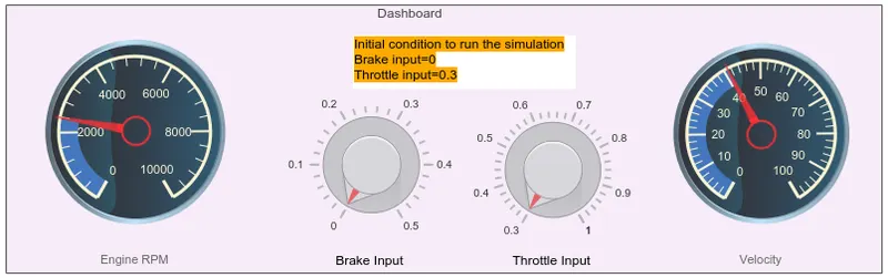
Dashboard Model Simulition ON.
FLOW PROCESS:
The model workflow process is same as the process os 'BAJA ATV Model_mapped lookup table without Dashboard but the throttle and brake inputs are controlled by the user with the Knob followed by the vehicle speed is given as feedback to the CVT Ratio lookup table.
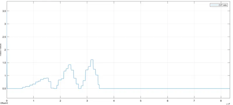
Relationship of CVT Ratio, Throttle Brake Inputs:
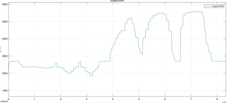
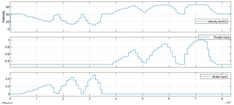
The relationship with Throttling, Braking in CVT Ratio respectively is in this BAJA ATV model the Engine per set to run at 3300 rpm with the throttle value of '0.3'. When the throttle is being increased the CVT Ratio reaches the state where engine speed is maximum. Whwn the throttle is being decreased the CVT ratio will move towards where the minimum engine speed state. While the braking is applied the cvt ratio increases so that nearest state of minimum engine speed. When the braking is removed the CVT Ratio decreases so that it achieve the state of maximum engine speed.
Engine RPM:
CVT Ratio:
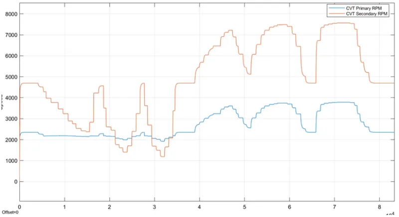
CVT Shaft Speed:
Vehicle Speed:
CONCLUSION:
System level Simulation of an BAJA All Terrain Vehicle without lookup table and using lookup table has been carried out and technical report for the model has been prepared and output results and plotted.