Project 2
Develop general arrangement for the RC office building. Analyze and design the building as per IS standard code in TEKLA STRUCTURAL DESIGNER. Refer the attached plan and elevation. The building to be designed for dead, live, wind and seismic loading.
Report of each member to be generated and extract drawings for structural plans, beam reinforcement details from the software
AIM
To create a model of Rc Office building and to analyze and Design as per Is code In Tekla Structural Designer.
PROCEDURE
1. To open the New Model file and save the File as appropriate locations.
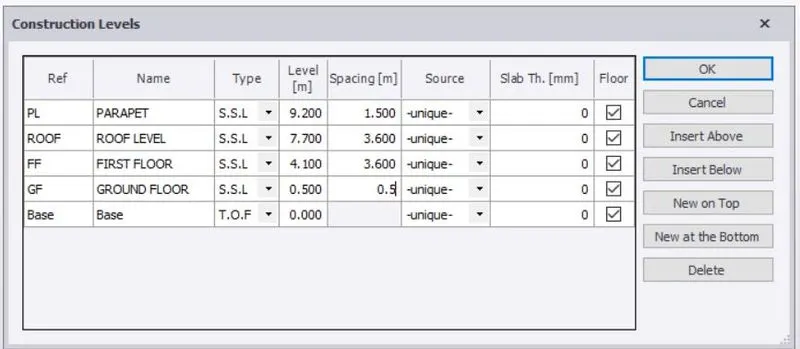
2. Go to Model > Choose Construction Level > add the Different floor level from one floor to another floor from taking the reference of Given Building plan.
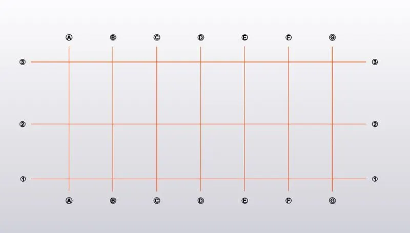
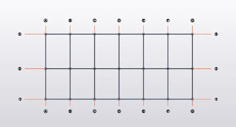
3. Go to Model Tab > Choose Grid Line option > To draw Gridline as a reference of Given floor plan Dimension. To consider both the direction Of Gridline in X direction we put a name for Alphabetic and Y direction in Numerical.
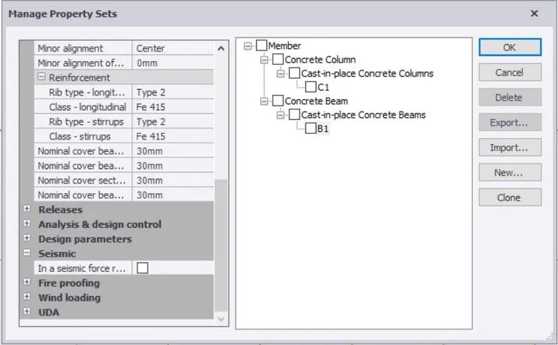
4. Next to Creata a material properties.
Go to Home Tab > Manage set properties > Go to new > member > concrete column, concrete beam and slabs.
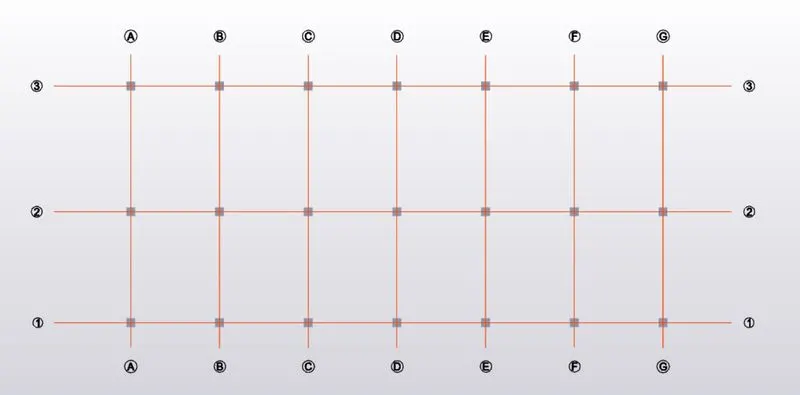
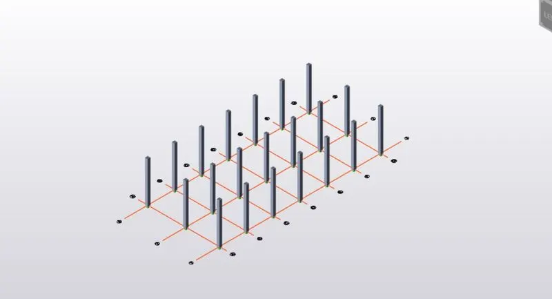
5. To model the column Go to Ground floor , to add the column at center intersection nodes. The main contribute to choose base level and Top level and to check 3D structure view.
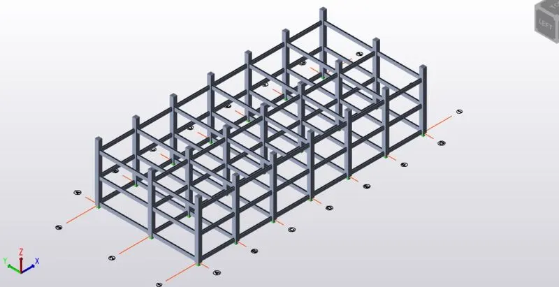
6. Similarly, to model the beam as the same procedure. To create a beam properties and to Draw proper pick and end point.
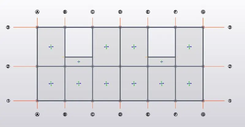
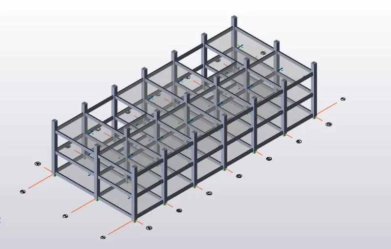
7.Go to model > choose slab on beam > To choose particular slab properties and to add all floor level.
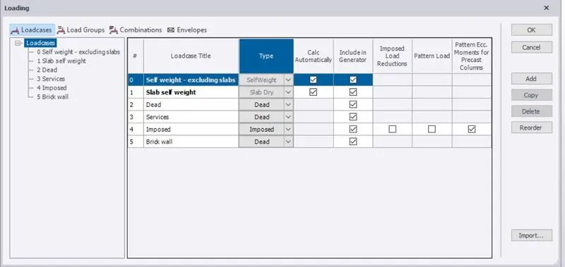
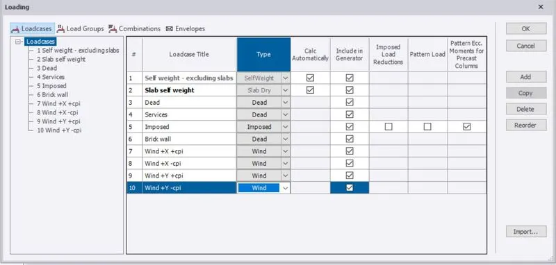
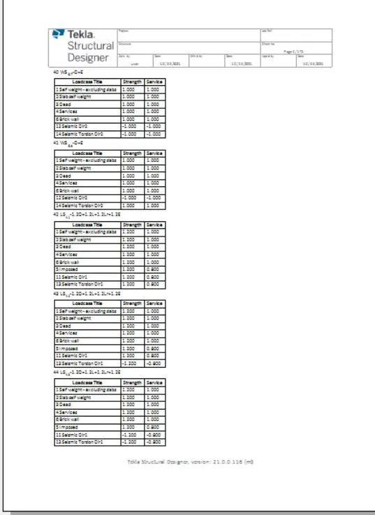
8. To create and add the required loadcases. Go to Load > Loadcases > open new dialog box and to add all type of loadcases.
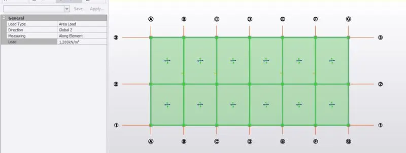
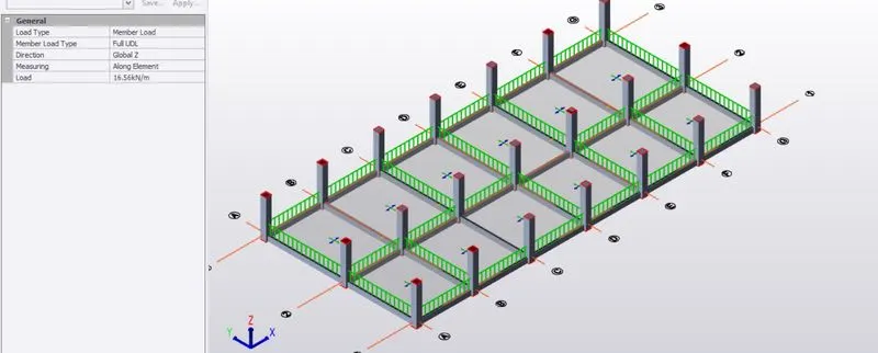
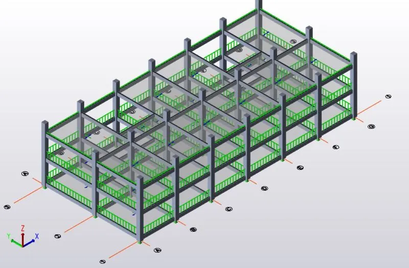
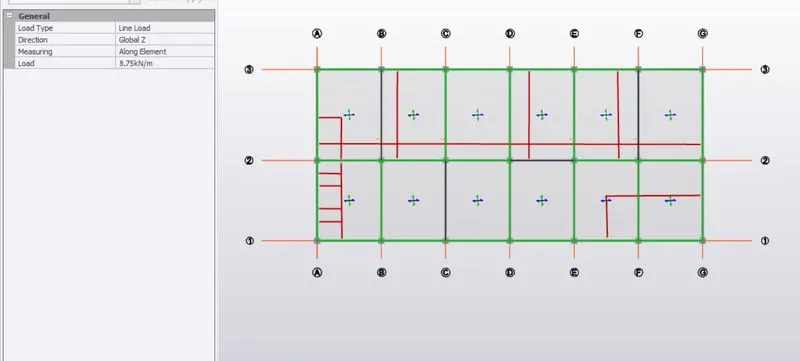
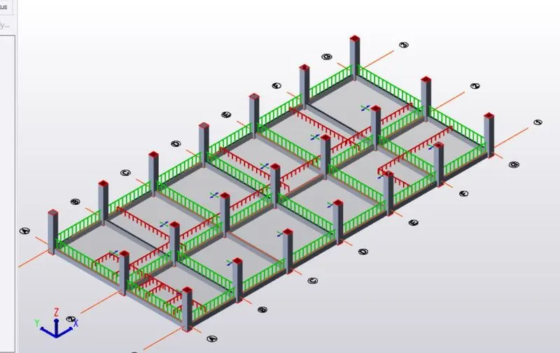
9.The main important role of Modeling for to add the load data of our model. To calculate the Dead load of Finishes load, service load, Brickwall load and apply the model at a particular places of reference from given building plan.
Calculation of Dead Load
- Finishes Loading ( 50mm thick )
= 0.05 x 24
= 1.2 KN/m^2.
- Brick wall load with cement plaster thickness.
Unit weight of brick wall = 20KN/m^3
@ Ground floor to First Floor ( 3.6m height )
- Exterior wall ( 230 mm thickness )
= 0.230 x 20 x 3.6
= 16.56 KN/m.
- Interior wall ( 125 mm thickness )
= 0.125 x 20 x 3.6
= 8.75 KN/m.
@ First floor to Top Floor ( 3.6m height )
- Exterior wall ( 230 mm thickness )
= 0.230 x 20 x 3.6
= 16.56 KN/m.
- Interior wall ( 125 mm thickness )
= 0.125 x 20 x 3.5
= 8.75 KN/m.
- Roofing load.
= 1.5 KN/m^2.
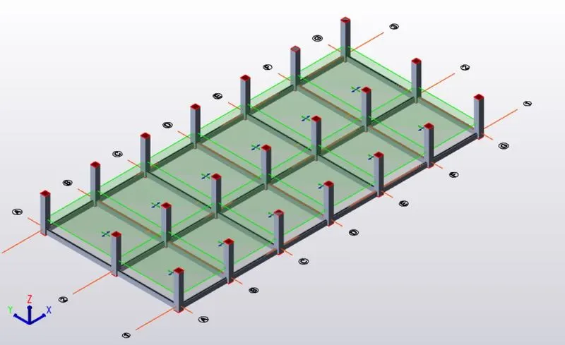
10. Similarly, we add the Live load to model
Calculation of Live Load
As we taken the value of all areas of Live Load from IS 875, PART-2, TABLE-1.
- Store room = 5 KN/m^2.
- Office room = 3 KN/m^2.
- Rest room = 2 KN/m^2.
- Toilets = 2 KN/m^2.
- Staircase = 5 KN/m^2.
- Equipment Room = 10 KN/m^2.
- Conference Room = 5 KN/m^2.
- Flat roof = 0.75 KN/m^2.
- Workshop = 5 KN/m^2.
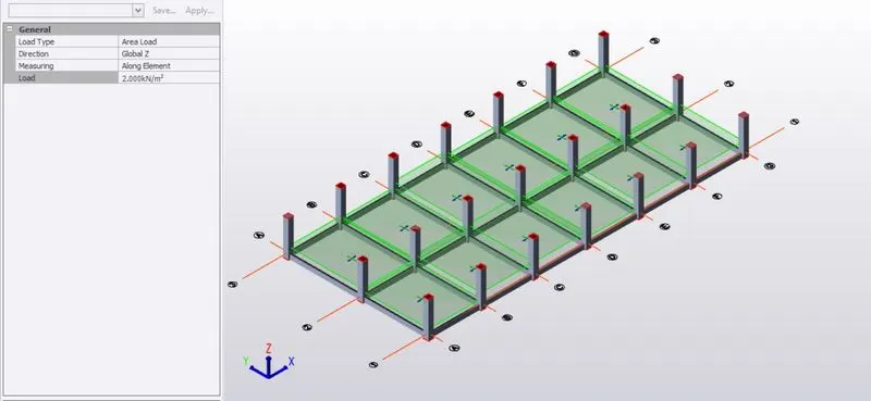
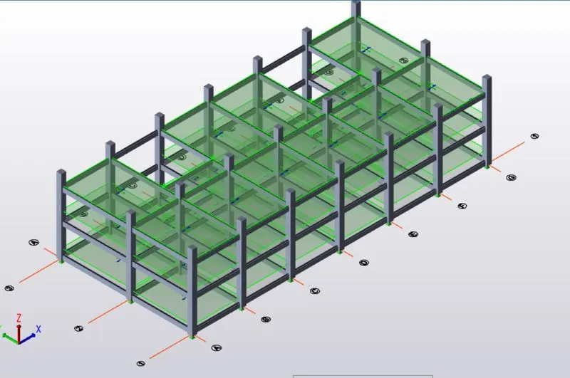
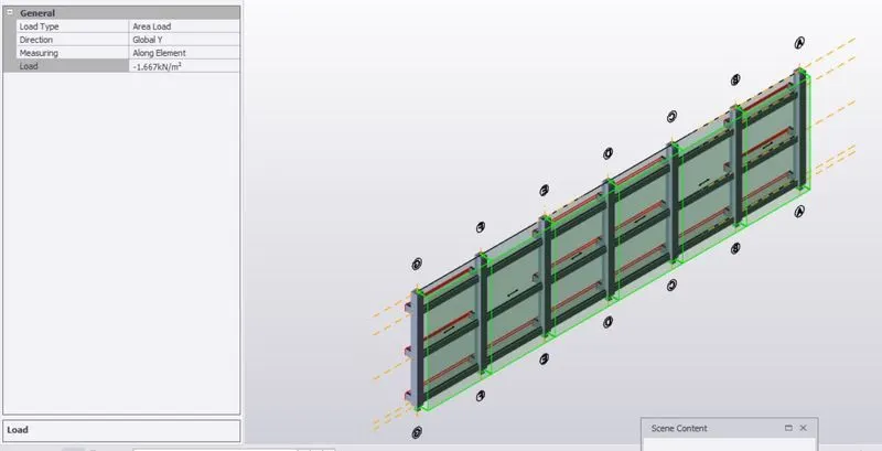
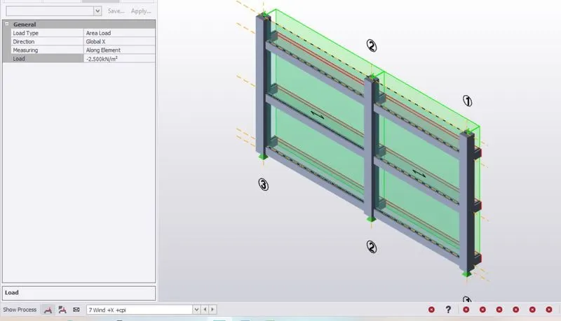
11. To calculate the wind load and apply the load to model with both the direction as per indian standard reference.
Data
- Basic wind speed, Vb = 50 m/s.
- Terrain category = 2
- Class of structure = A
- One horizontal dimension of structure, L = 36 m
- Another horizontal dimension of structure, W = 16 m
- Height of structure, h = 8.7 m
SOLUTION
- Ratio of wall and Roof Co-efficient
Wall , L/W = 2.25
h/w = 0.55
ROOF, h/w = 0.81
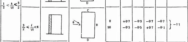
- As per reference of IS 875, Part – 3, Table =5.
- To find external pressure co-efficient(CPe) for walls.
The condition is satisfied in,
- To find Design Wind pressure (Pz).
Pz = 0.6*Vz^2.
- To find Vz,
Vz = Vb * k1 * k2 * k3* k4
Therefore,
As we take value of k1, k2, k3, k4 from IS 875.
K1 = 1 ( under basic wind speed)
K2 = 1.0 ( height upto 10m)
K3 = 1
K4 = 1.15 ( for industrial building )
Vz = 50 *1*1*1*1.15
Vz = 57.5 m/s
Then to find,
Pz = 0.6 * (57.5) ^2
Pz = 1.983 KN/m^2.
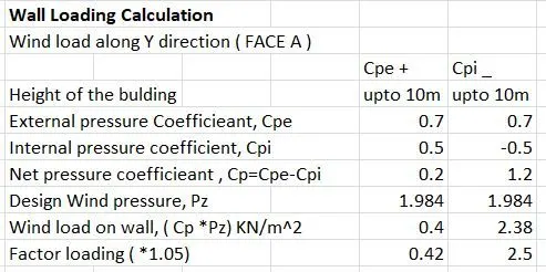
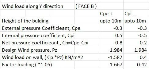
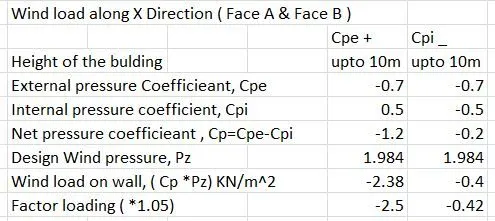
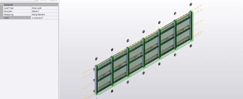
To add the wing load cases into the Loadcases category and to apply the wind load to model in all direction.
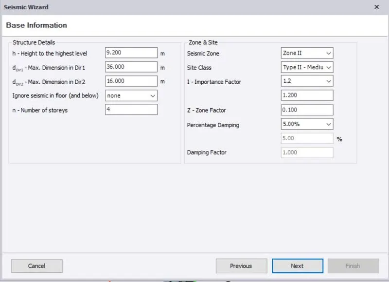
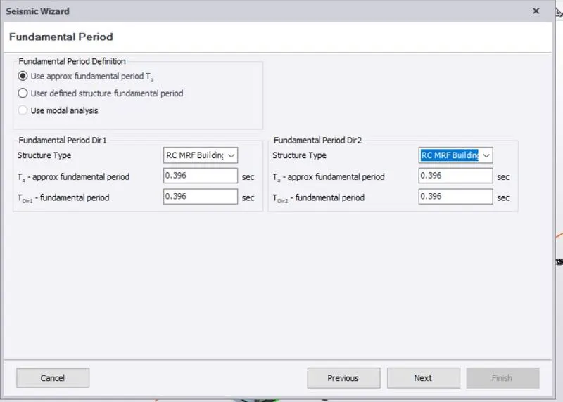
12. Go to load tab > seismic load > seismic wizard , then to check all data of loads and to check all details of building information.
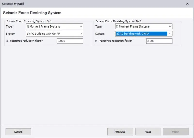
13. Next, to analyze the model. Before we check all parameters of the whole model of Auto design standards, Material properties, etc.., Go to Analyze tab > Choose 1st Order Linear and to switch on all loadcases and loading combinations.
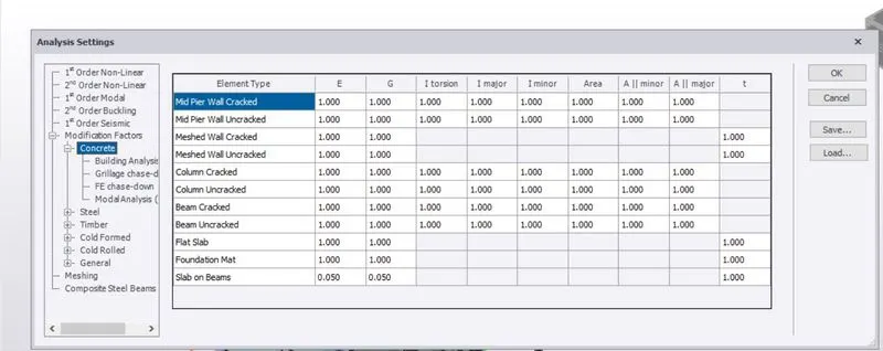
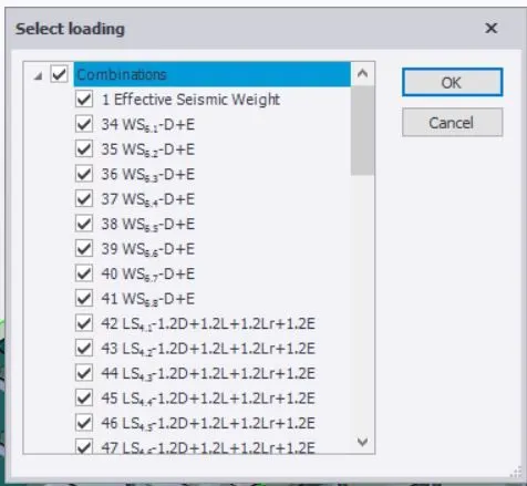
14. After Analyzed the model, to check the Axial force, Shear major, Moment major with the value of Forces, deflection and Reaction in all direction. Go to Result view and choose this all parameters and check whether it is all ok or not.
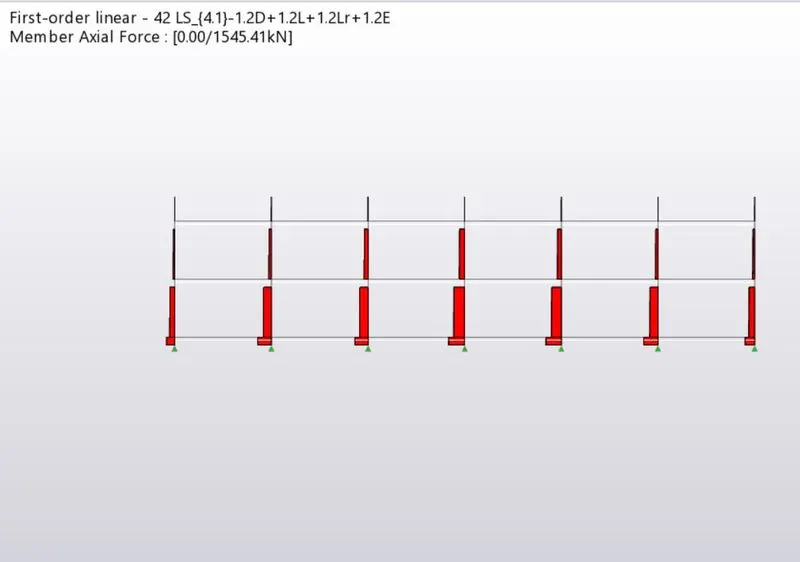
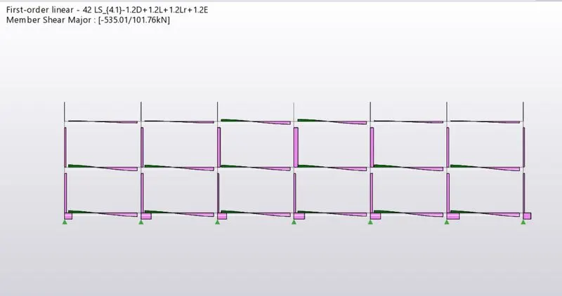
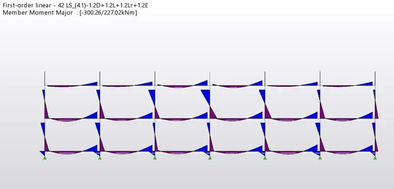
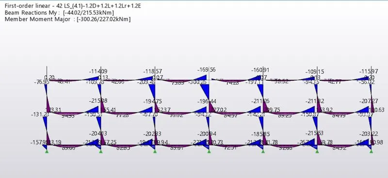
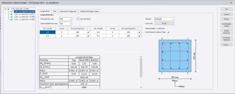
15. Go to Result view > check all column whether it is Fail or not. If any problems id there, to right click the column > Interaction design > static and to heck the column detailing.
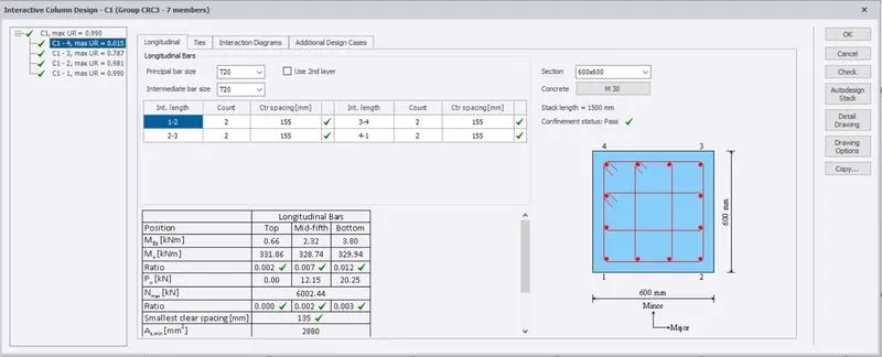
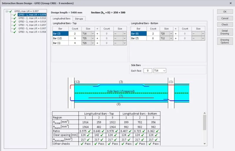
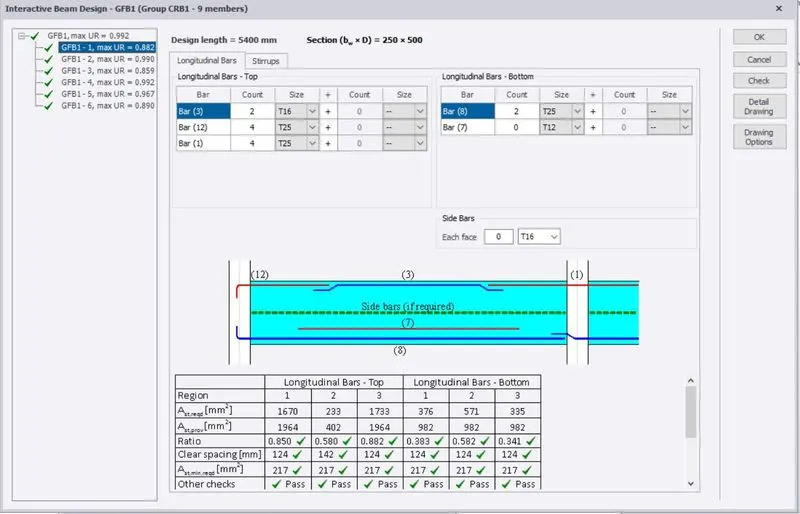
16. Similarly, to check the Beam characteristics.
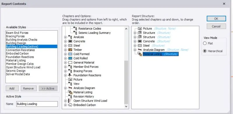
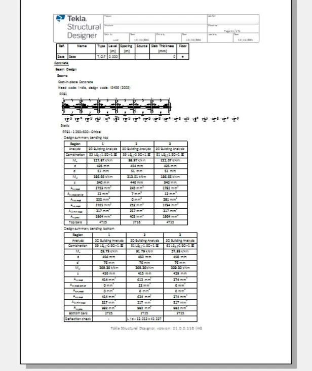
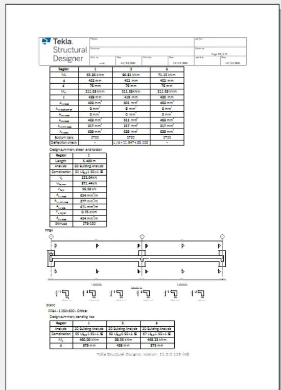
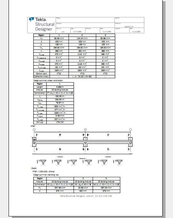
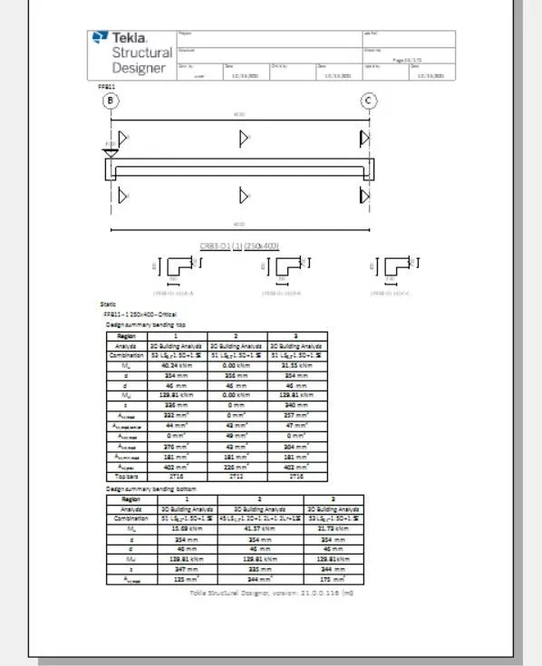
17. To create a Report of our model, Go to Report Tab > Select the properties and to add whatever we need to add the required stages.
To be created the report of Drawings of structural plans and Beam reinforcement details.

RESULTS
The above following steps we can successfully design and Model the structure as per given data. To created the report for Building further process requirement.