Project 2
Report on Wiring harness on Backdoor of a car
Aim: To route the wireharness in the backdoor of car and application of all packaging rules and industry best practice with placing the appropirate connectors at the different functioning location like tail light, wipermotor, number plate light etc. and flatten the created harness to represent it on drawing sheet.
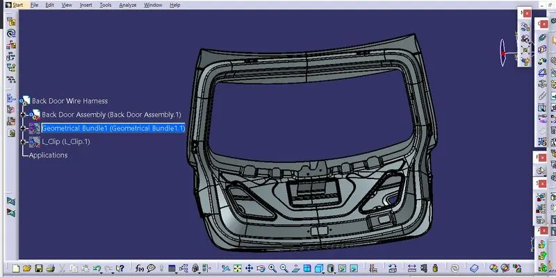
Given Backdoor Cad data:
Step 1: First we selected two pole connector for the tail light left and right, no. plate light, locking sensor, rearview camera so total there are 7 two pole connectors, 1 four pole sealed connector at wipper motor.
- We selected fir tree clips to prevent the fouling of bundles and provide support to them.
- P clamps are selected to provide guiding support to them.
- After selecting these part we electrically define each part and add them into the main product file containg the backdoor part file and geometrical bundle product file when required.
- Our parts are as shown below:
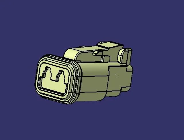
- Electrically defined two pole connector DT06-2S:
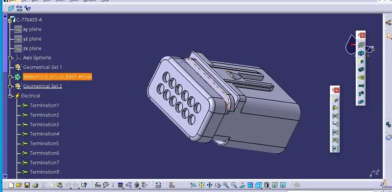
- Electrically defined sealed connector C-1563689-1:
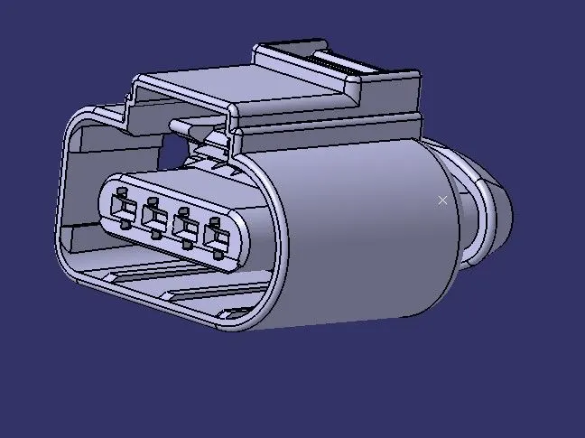
- Elctrically defined interconnection connector:
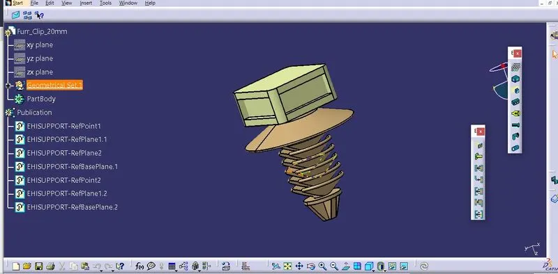
- Electrically defined fir tree clip:
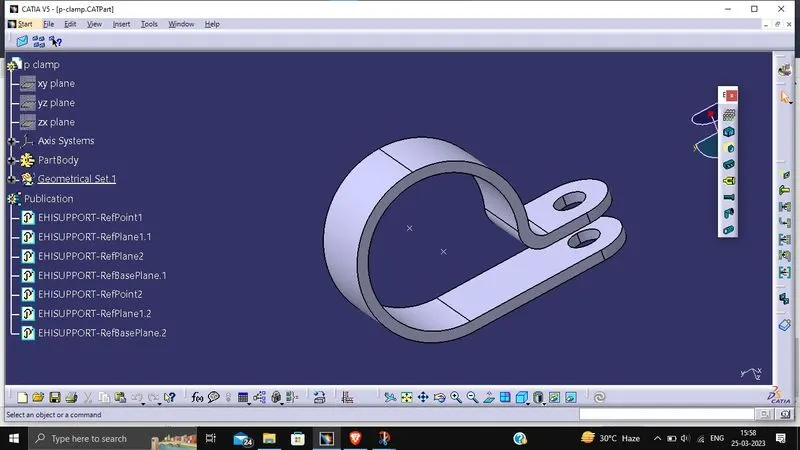
- Electrically defined P clamp:
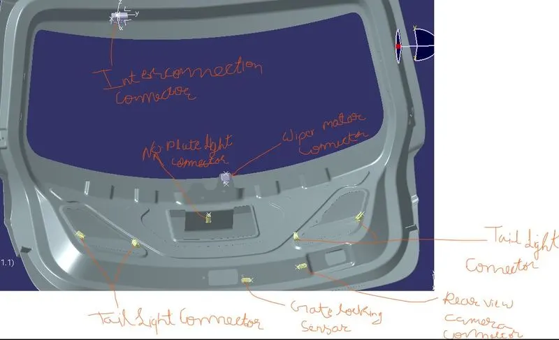
Step 2: Now position each component at the required location such that.
- Main interconnection connector is placed on top of seling flange which connect the entire circuit to other circuit.
- Two 2-pole connectors on the each tail light, one on gate locking sensor, one on rear view camera area, one for no. plate lights.
- One four pole connector for wiper motor so it is placed near to it.
- P clamps are placed accordingly to guide the bundle and to avoid twisting.
- Fir tree clips are place to avoid fouling of bundle and provide support to the bundle so they are placed accordingly.
- We placed all the parts by using the commands like manipulation, compass movement and smart move.
- Finally our backdoor with attached components will look like this:
Step 3 : Now start routing the bundle starting from interconnection connector.
- We route the wire with taking the bend radius ratio of minimum 1.4 for each bundle.
- Diameter of main bundle taken as 15 mm, and bundle connecting the connectors taken as 5mm .
- Each branch is of length 50 mm minimum.
- Branch point should be place at distance of minimum 25 mm from clips and clamps.
- Fir tree clips are used to prevent the fouling and provide the support.
- So our final routing look like this:
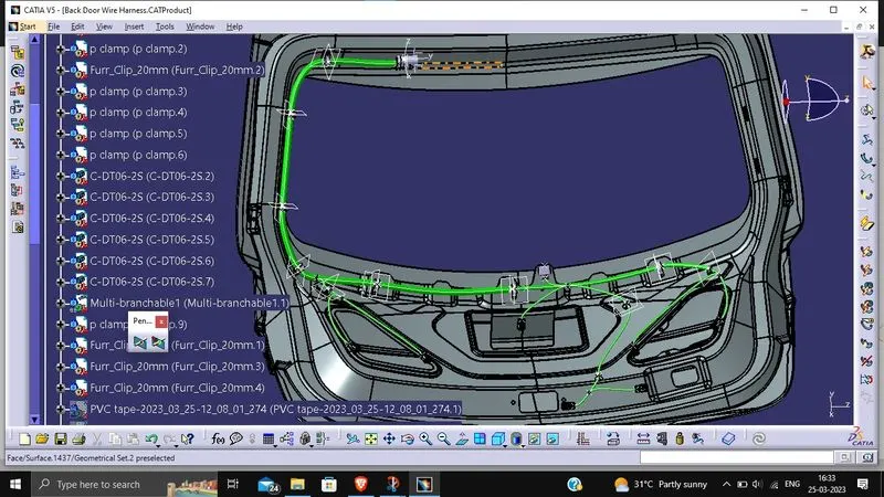
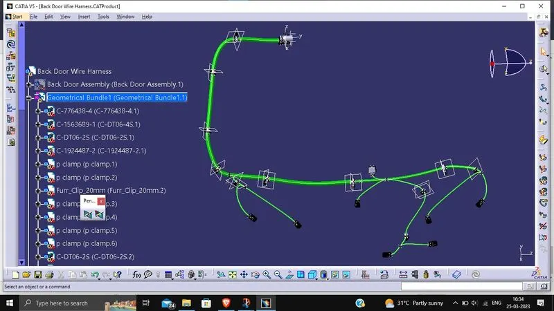
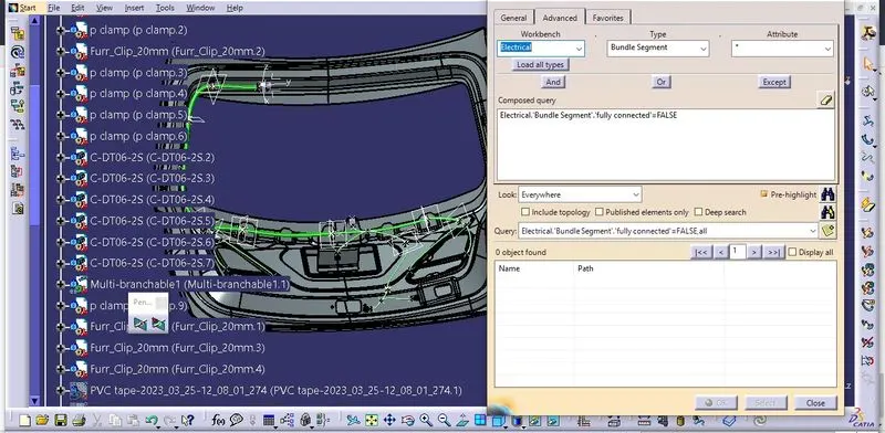
- Checking the continuity of bundle segemnt we got the result as shown:
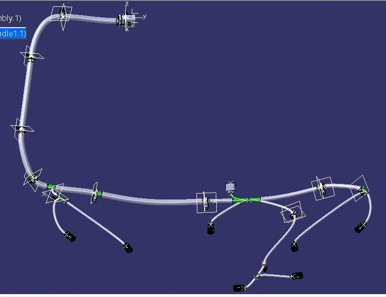
Step 4: Add protective covering like PVC tape on the bundle segments this covering will provide tight covering around the bundle and also provide thermal nad moisture insulation.
so after adding the protection coverings our design will look like this:
Step 5 : Now flatten the wire harness by using the flattening wire harness workbench.
- First create the new product file for flattening then define the falttening parametrs in it as shown below:



- Now extract the geometrical bundle from the main product file, and flatten it using the flatten command, then use the command such as quick roll, rotate to make the harness of comapct size as shown below:
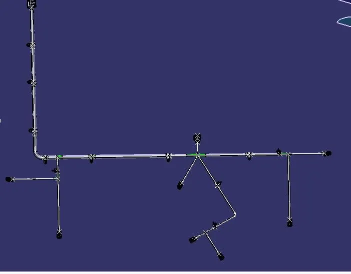
Step 6: Now create the 2D drawing out of the flattened design.
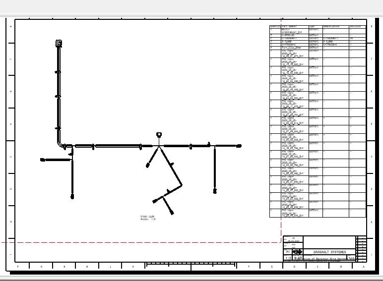
- Create a new drawing file select the sheet size of A2 in iso standard, now add the front view of flattened wire harness in the drawing sheet.
- Change the scale of drawing to 1:2 and define the properties of front view as shown below:
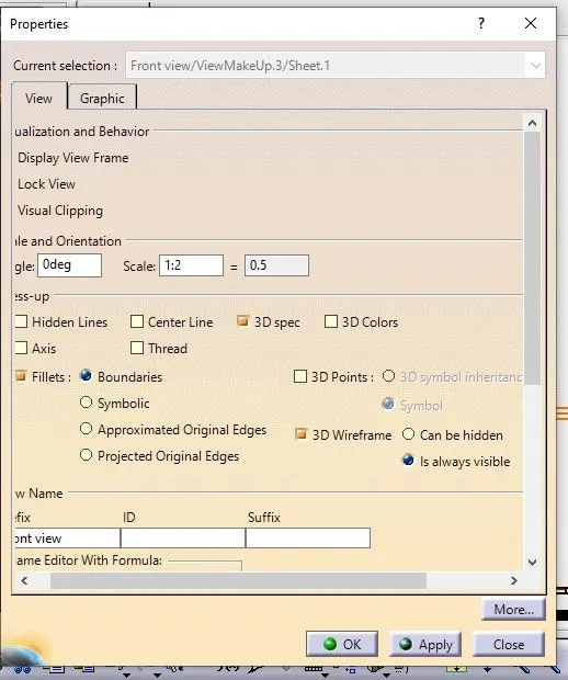
- Add the frame and title box in sheet background also the bill of material also be added so our final drawing sheet will look like this: