Project 2
Project 2 - Backdoor Wiring Harness Assembly:
Aim:
Route the Wiring harness on Given car body and Prepare flatten view drawing in CATIA V5. Application of all Packaging rules, Industry best practices studied in this course shall be demonstrated in design. Apply Protection coverings as required.
Introduction:
Backdoor Wiring Harness Design:
A wiring harness is a systematic and integrated arrangement of cables within an insulated material. The purpose of the assembly is to transmit signal or electrical power. Cables are bound together with straps, cable ties, cable lacing, sleeves, electrical tape, conduit, or a combination thereof. The wire harness simplifies the connection to larger components by integrating the wiring into a single unit. There are four main steps in electrical system design:
- selection of component,
- wiring diagram,
- wiring harness
- electrical routing.
Selection of Components:
Selection of connectors, fuses, lights, switches, sensors, wires, cables, relays, protection tubes, motors etc. are the core components of the wiring harness. The performance of these components directly determines the overall performance of the wiring harness and plays a decisive role in the stability and safety of the whole vehicle. The basis of the selection of these components is the voltage system and its current carrying capacity. Ambient temperature in the selection of these components is one of the most important aspects of wiring harness design. Proper selection of these electrical components and their conductors ensures reliability and safety. For example, for the requirements of high performance airbags like ABS and ECU with a terminal connector, gold-plated pieces are preferred to ensure safety and reliability.
For the backdoor harness required connectors for main interconnection, Fur tree clips are used to mounting the harness and different gauges of wires has been used to connect the bundles.
Wiring Diagram:
Wiring diagrams are also known as schematics or circuit diagrams. The selected components are placed and connected to each other in the diagram. These components belong to a set of libraries which can be modified and configured according to customer specific requirements. A wiring diagram shows each connection in detail. The schematics give an overview of the components that are part of the electrical design. Other items in the schematics are for example cables, sheet cross references and ECUs.
If an assembly is going to be used for communications or data signal transmission, twisted pairs should be considered to eliminate the risk of noise or EMI (electromagnetic interference) impacting on the performance of the assembly.
Wiring Harness:
The entire vehicle is divided into parts which are detachable and the wiring harnesses are designed accordingly. This process also involves generating a connection list and a BOM (bill of materials). Harness passes through many areas where it requires protection against heat, dust, moisture etc. Wire harness protection prevents damage caused by wire vibration damage, abrasions and incidental contact with other pieces of heat-producing equipment.
Thermal management tubes and sleeves are designed to operate under high temperatures and provide superior fire resistance under extreme conditions. These tubes and sleeves are difficult to ignite, and they self-extinguish promptly. The most common types of cable and wire protection are braided sleeving, corrugated loom, heat shrink, vinyl tubing and conduit. A typical wiring harness drawing has cable lengths, component view, grommet, connector specifications and inline connectors.
Electrical Routing:
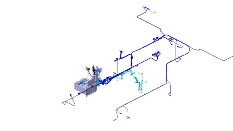
The lengths of the harnesses in the harness drawing are derived from the 3D models. Harness installation drawings are generated via 3D routing. The routing feature creates a unique type of subassembly which builds paths of electrical cables between the components. It ensures flexibility between two or more components and helps in deciding the path through which the cable should run to avoid further complexity. This helps in understanding the path followed by a particular harness.
Objectives:
- Define the mechanical components electrically and prepare the catalogue for the components
- provide support parts like clips and clamps
- Provide proper routing of bundle without interference
- Apply protective coverings
- Creating the flattening file using flatteing workbench
- create the 2D drawing using Drafting workbench
Components used in Harness Assembly:
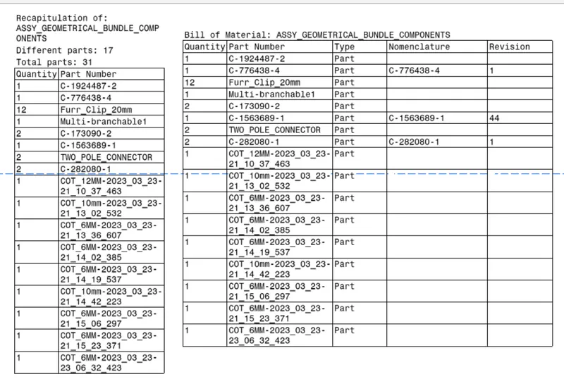
- C-776438-4 - Used for main interconnection
- C-1563689-1 - Used for wiper motor connection
- Two pole connector - Used for break light
- C-173090-2 - Used for indicator light
- C-282080-1 - Used for number plate light & Lock sensor
- Fur tree clip - Used for supporting the bundles
- Cot tubes - Used for Protecting the bundles
Define the components electrically:
Connectors:
- First step is to create the parameters of the all mechanical connectors using mechanical part workbench.
- Next step is to create bundle connection point and create connector connection point.
- Then create connector connection axis, where Y axis facing towards connector entry and X axis toward locking mechanism.
- Then define the connectors electrically using electrical part workbench.
- First step is define the connector and terminals using connector option.
- Then Define bundle connection point option to define bundle entry position.
- Then Define connector connection point option to define connector entry point.
- Then add the connectors in the catalog.
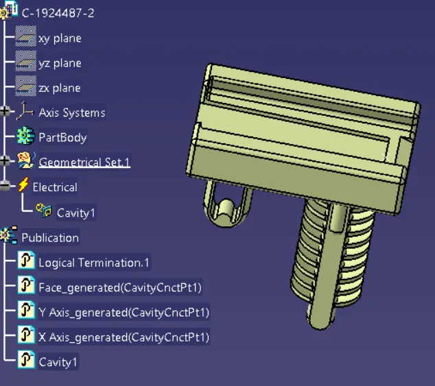
- If cavity is present define the cavity using define cavity connection point option.
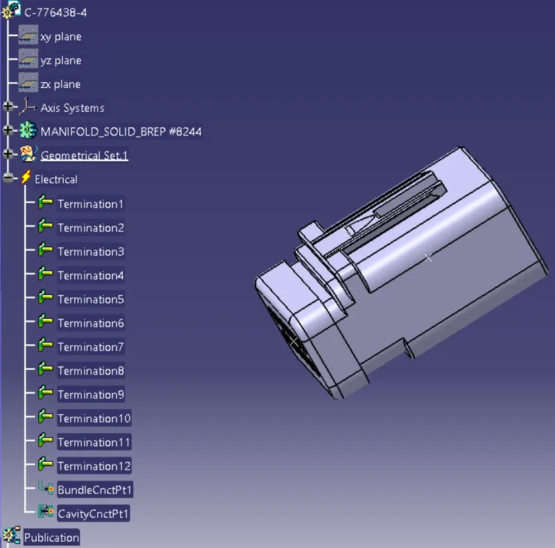
- Create a points using point command from part work bench.
- Then for creating cavity connection point, choose point type as on curve and select the line of the locking pad and choose middle point option to create a point.
- Connector clip Cavity Axis system has been created using axis system command from part work bench
- Then choose axis sytem type as standard and selct the orgin as connector connection point.
- And adjust the coordinates of X axis pointing in the direction of locking mechanism, Y axis pointing towards the front face of the connector.
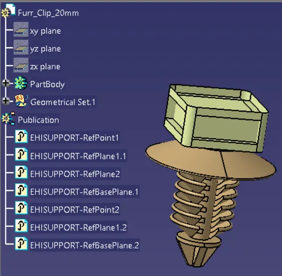
Fur tree clip:
- Created the appropriate parameters using part work bench
- Then use define support part option to define bundle entry and exit point from electrical part design work bench
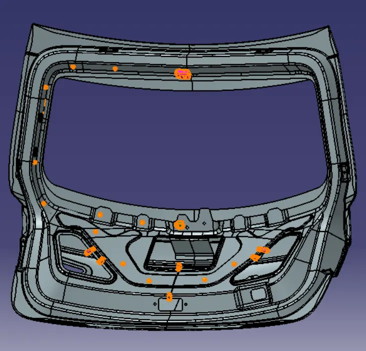
Creation of Harness assembly Context:
- Create context product file from assembly workbench
- Here the back door product file and harness components product file were added to make context assembly.
- Then placing the components in appropriate location to create bundle assembly
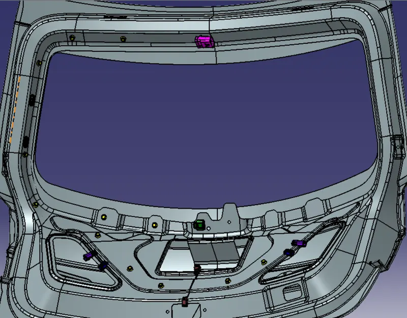
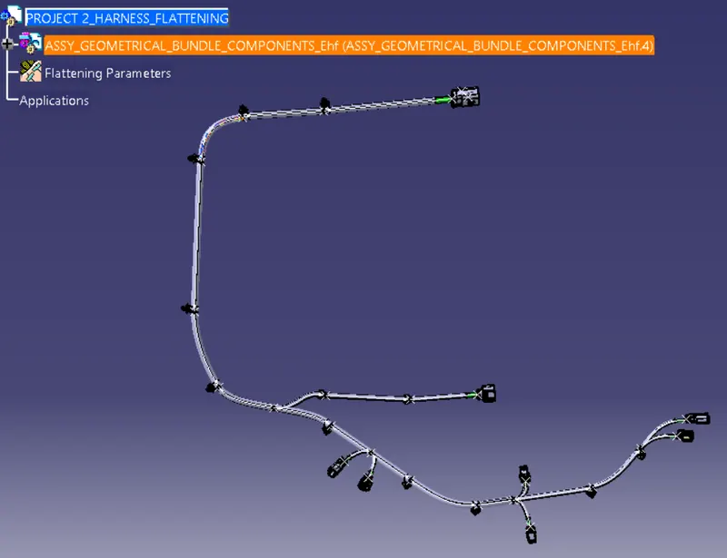
- Then activate the assembly geometrical bundle electrically using geometrical bundle option from electrical harness assembly workbench
- Then choose multi branchable document option to create multibranchable file in the geometrical bundle.
- Then use add branchable option to create bundles of each components.
- For creating the branch points using add branch points option.
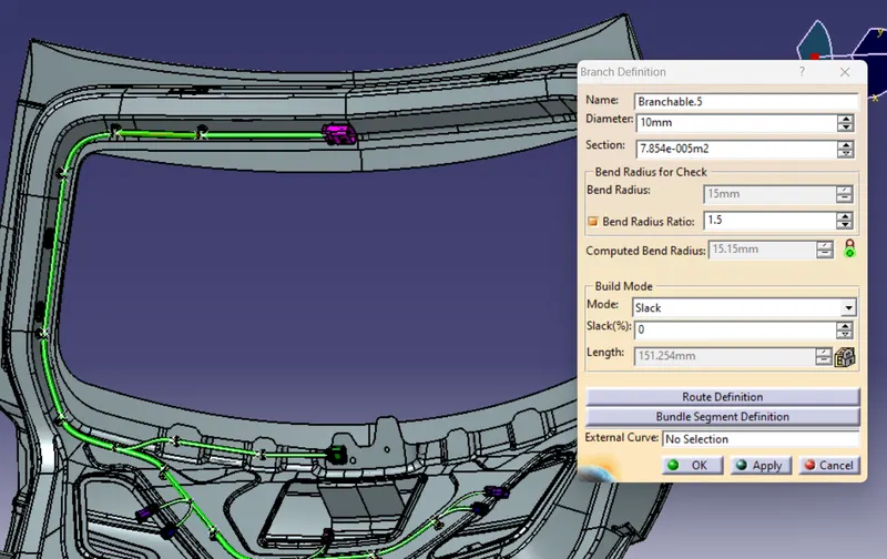
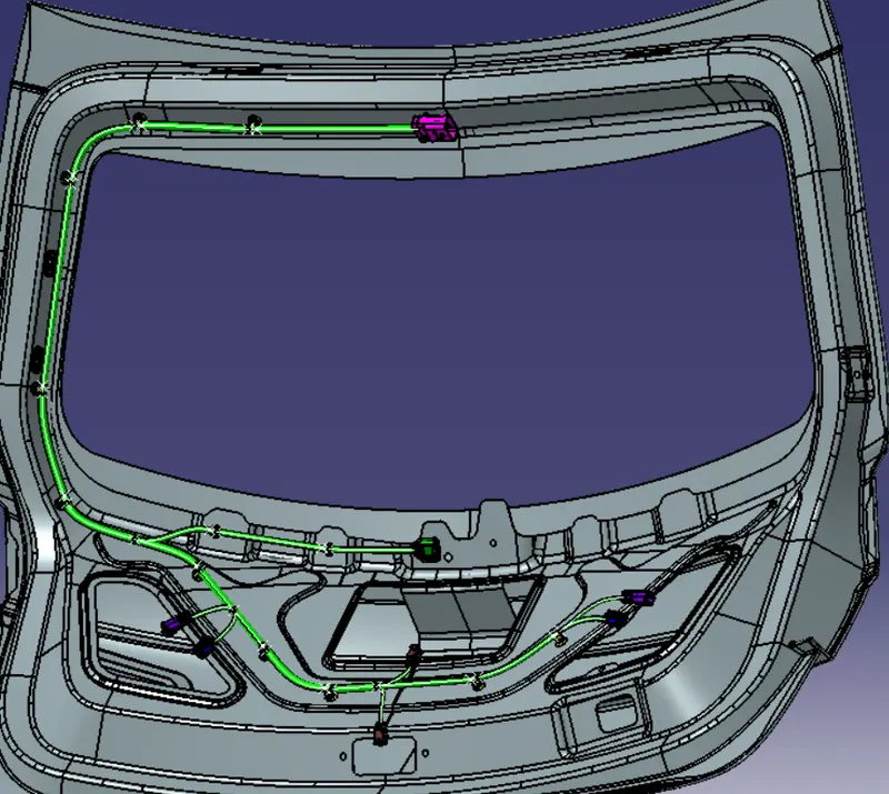
- Then the next step is adding the protection covering of harness bundles
- For adding protection covering choose protection covering option and select the appropriate cot tubes from the catalog and choose the bundle segment which will need protective covering and click ok.
- Following the above steps to add protective coverings in the required bundle.
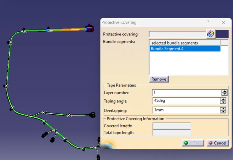
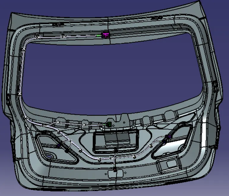
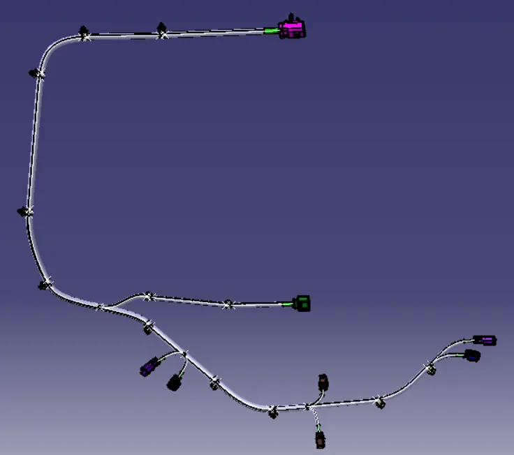
- The next step is to check the Bundle connectivity.
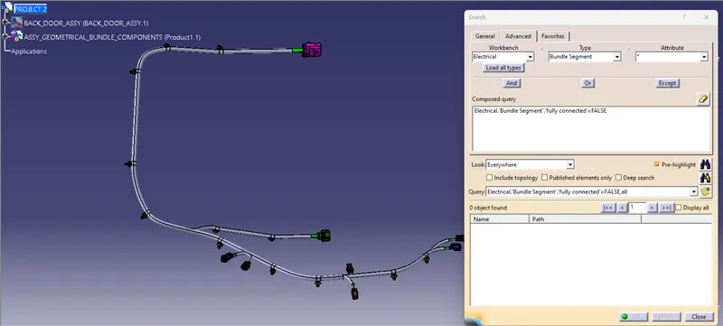
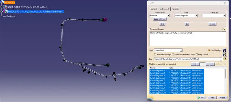
- For checking the bundle connectivity go to edit-search-advanced-attributes fully connected and check the connectivity in true and false option
Creation of Bundle Flattening:
- After completing wiring harness routing next step is Bundle flattening, It has been done from electrical flattening workbench.
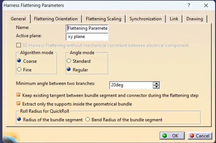
- Initial step is to set the Harness flattening parameters using harness flattening parametes option.
- Then next step is to extract Geometrical bundle assembly file from tile vertical window.
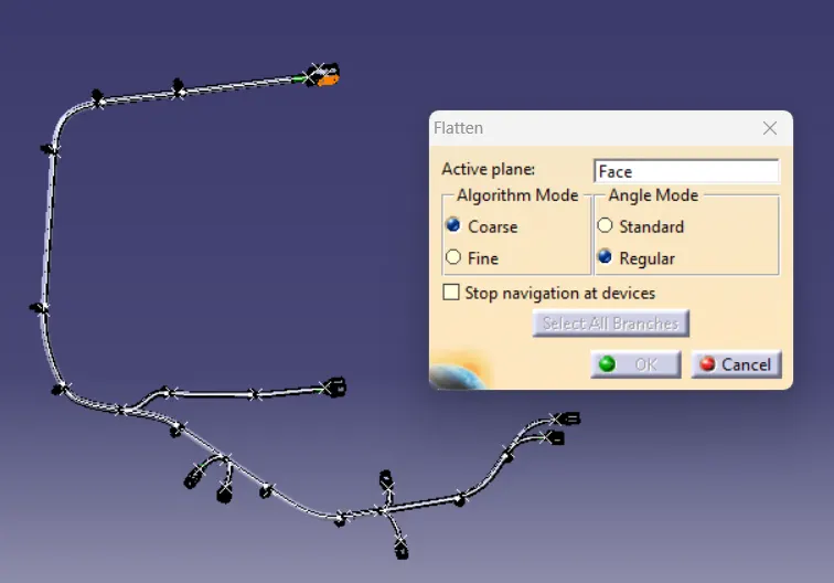
- Then next step is flatten the bundle using flatten option, where have to select the plane and choose the bundles for flattening and click ok.
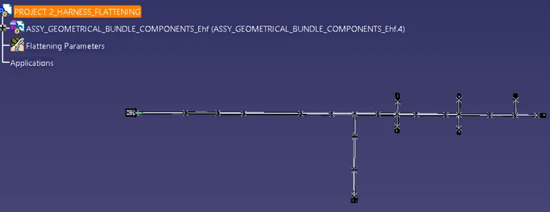
- Then have to arrange the bundles using rotate command.
- And then arranging the connectors and clips using manipulation tools from part assembly workbench
Creation of Harness Flattening Drawing:
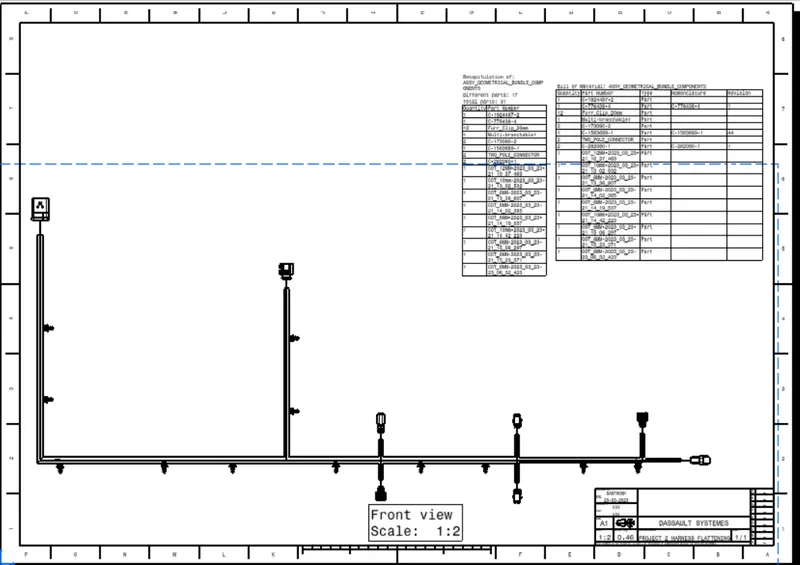
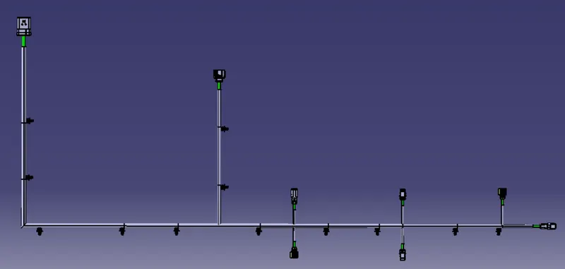
- After creating Flattening of harness next step is 2D drawing creation, It has been created from Drawing workbench.
- Initial step is to select the front view of the harness flattern assembly connector face, then click ok.
- Then adjust the drawings as per the parameters from the properties option.
- Then Add the title block and bill of materials from background views toolbars.