Project 2
'WIRING HARNESS ROUTING DESIGN ON BACKDOOR/TAIL GATE OF A CAR'
Aim of Project:
To Design and develop the Wiring harness on Given tail gate of a car and Prepare flatten view drawing in CATIA considering all industrial packaging rules.
Input:
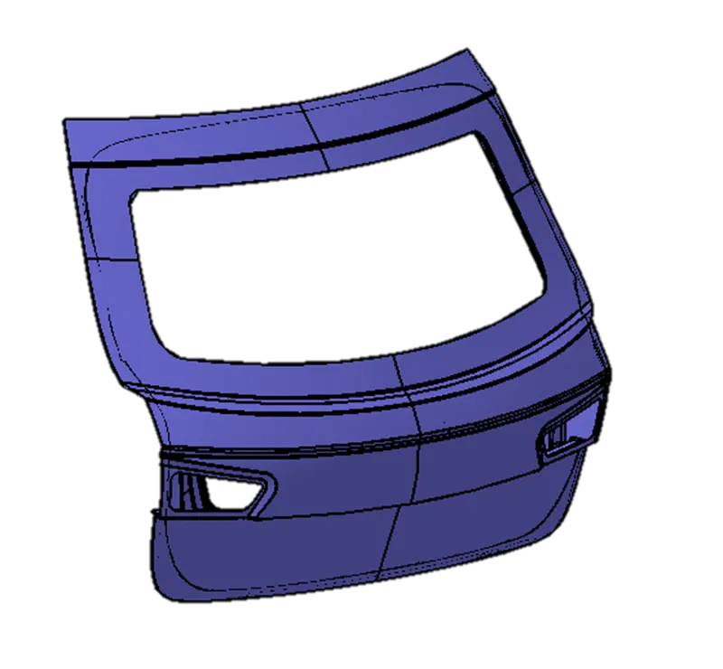
A back door is a hinged door attached at the rear end of the vehicle. It may be used for loading and unloading cargo, or to get passengers in and out, in case there are seats present at the rear. The back door comprises of certain components which form the back door assembly together.
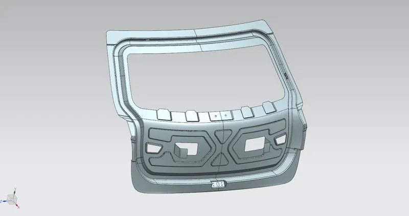
- Inner Panel: The inner panel, as the name suggests, is the inner part of the door. It is where most of the reinforcements and components are mounted. It is manufactured either by casting (aluminum) or sheet metal stamping (steel).
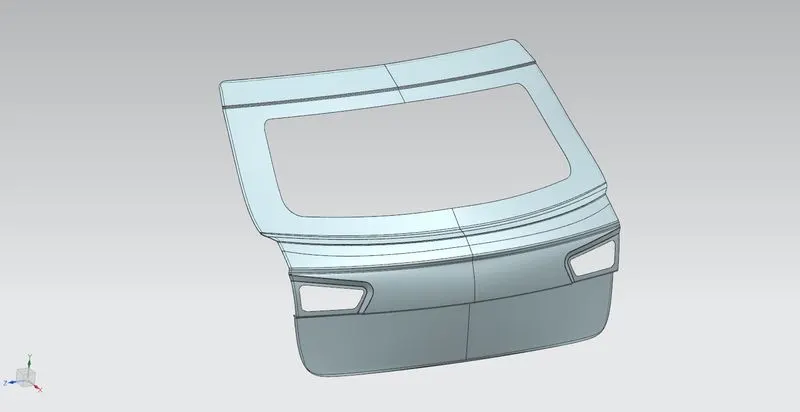
- Outer Panel: The outer part of the rear door and is mostly responsible for aesthetics of the vehicle. Outer and inner panels are connected by mastic sealants in center and by hemming process at edges. The outer door handle and in some cases. Outer panel comprises of windshield,wipers , parking sensors camera,taillights etc which is usually visible from outside.
Our main area of concern is the inner panel as it is the area where all wiring harness is routed
Some important packaging rules to be considered during wire harness routing:
- We have to avoid harness routing and clipping in blind zone
- We need to provide additional slack to the according to surroundings
- We have to provide enough clearance for the wire harness
- We have to follow guiding channel if provided in design
- We need to use fur tree and avoid using bigger clamps like p clamp Enough clamps and also ensure clearance with surrounding
- Minimum distance between clip and branch point should be 23 mm
- Maximum branches on a single point should be 4
- Wiring harness routing should be easy in manufacturing, accessibility, maintenance and removal.
A wiring harness, is an exterior sheath used to cover some types of electronic wires. Generally, wiring harnesses are made of thermoplastic or thermoset materials that can help protect the cables from the high temperatures and other foreign particles such as water,lubricants etc.
DESIGN METHODOLOGY:
Step 1: We have to Create a Context Assembly which will work as main assembly and it will contain the backdoor data and harness geometrical bundle assembly and any other mounting parts can also be added to context assembly.
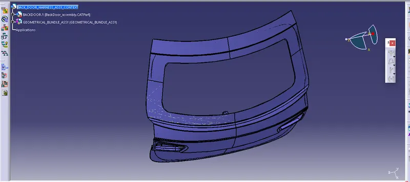
Step 2: We have to define all the mechanical connectors and other clamping parts electrically in electric part workbench and save it in the Catalogue so that we can use it next time in some other project.
1) Interconnector C-776438 : No of termination is 12
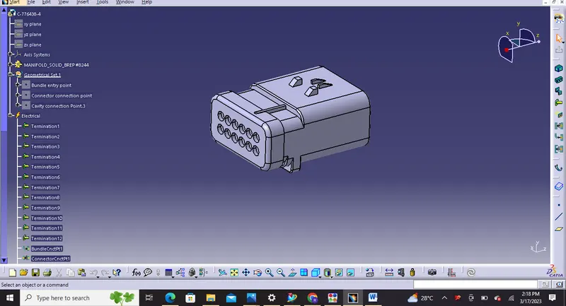
Electrically defined
2) C-DT062S : No of termination is 2
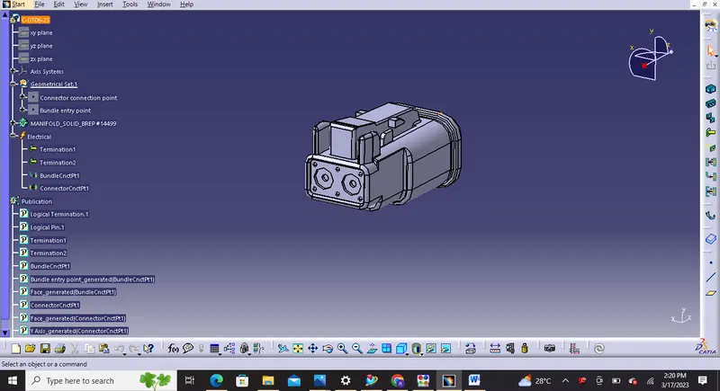
Electrically defined
3) C-DT064S : No of termination is 4
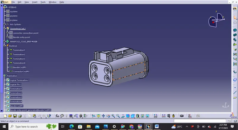
Electrically defined
4) C-1563689 ( Injector Connectors) : No of termination is 4
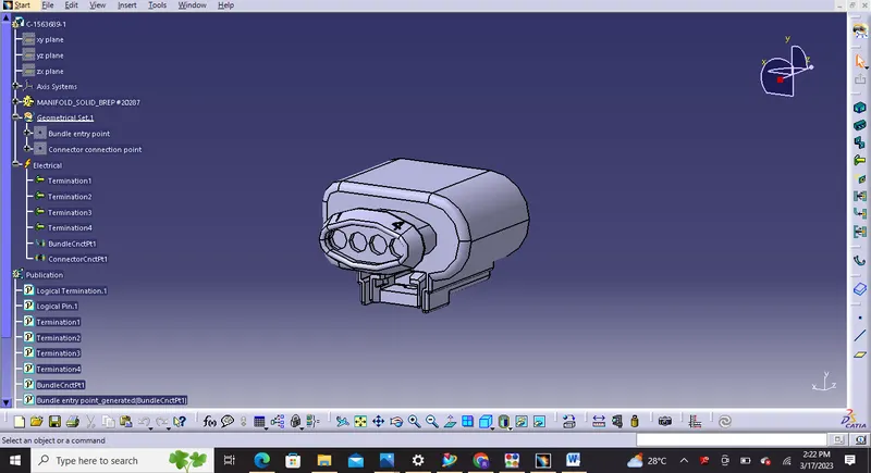
Electrically defined
5) FUR TREE
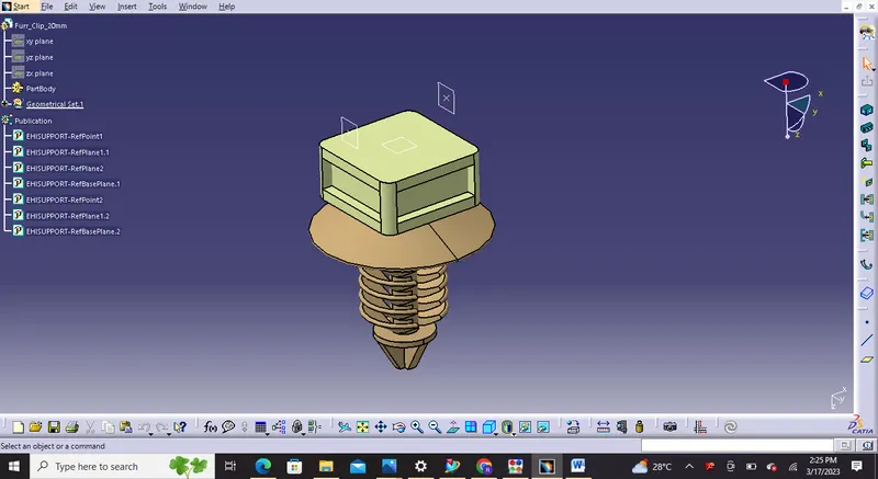
Electrically defined
Step 3: We have to create a catalogue for connectors.
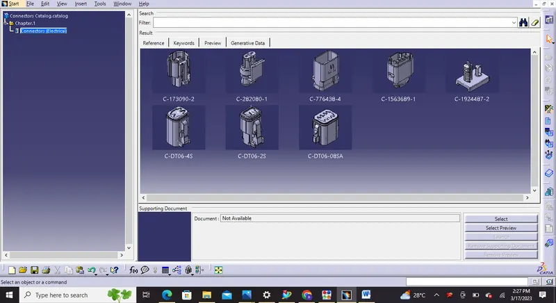
Connectors Catalogue
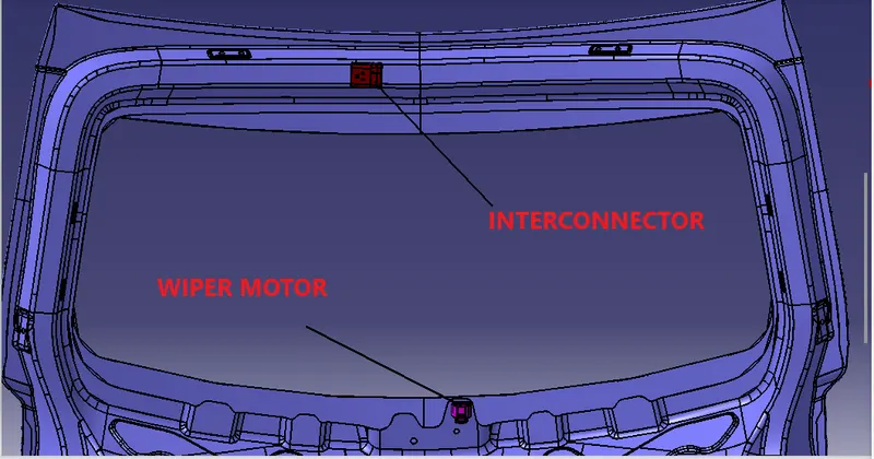
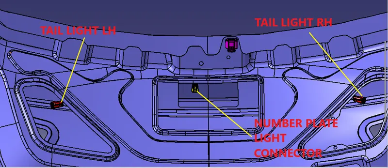
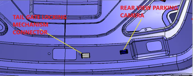
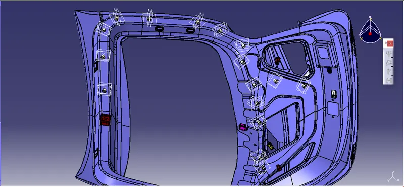
Step 4: We have to place all the connectors to the required positions on the given Backdoor 3D CAD model along with all other necessary mounting equipments.
Fur Tree
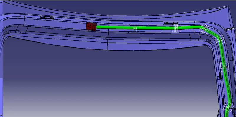
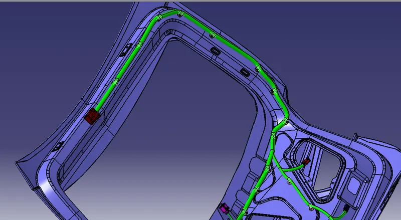
Step 5: We have to route connection in 'ELECTRICAL HARNESS ASSEMBLY' workbench
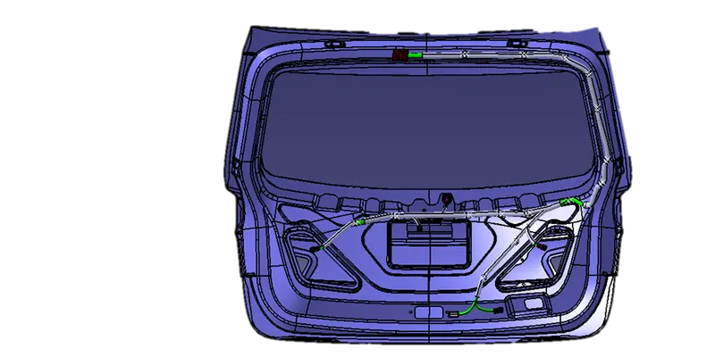
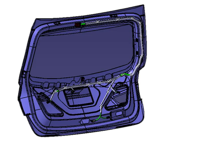
The Bundle routing starts from Interconnection connector to Fur tree. The diameter for this routing path is 15mm and bend radius ratio is assumed to be 1.4 whereas for other areas i have used 10mm and 5mm bundles.
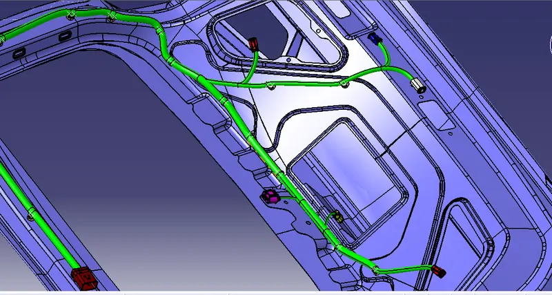
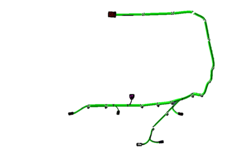
Step 6: We have to add protection coverings in the bundles like Corrugated Tubes
Steps to create Corrugated tubes:
1) we have to switch to electrical part design
2) Then select Define protection part
3) Click on part in specification tree
4) Then finally we need to provide the given parameters such as inner radius , bend radius and thickness etc '
#Note: Bend radius will be 1.5 times the outer dia of tube
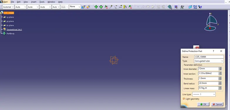
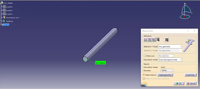
Tubes will be created
We can create different Corrugated tubes with diameter of 20mm,15mm,10mm,5mm etc and store it in catalogue
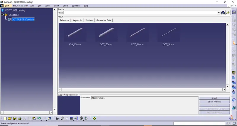
Cot Tubes stored in catalogue
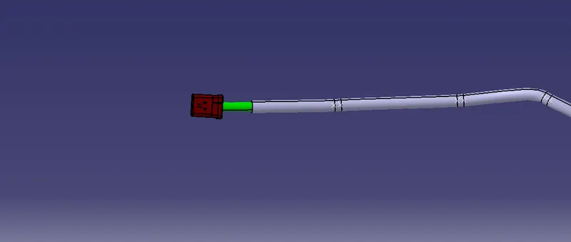
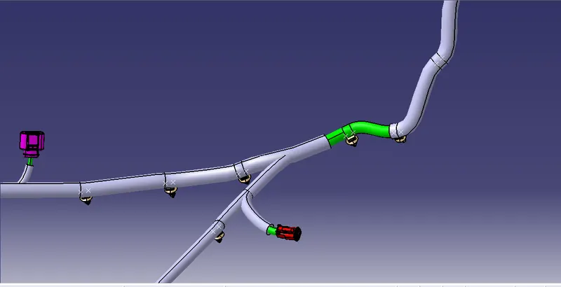
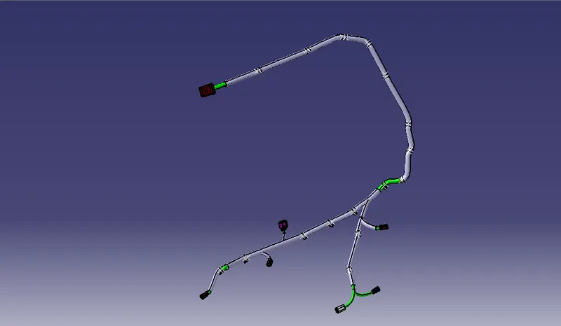
Protective coverings added on required places
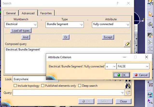
Step 7: We have to perform Bundle Continuity Check ,We have to make sure that multi-branchable is selected then we have to click on Edit>Search>Advanced>Workbench-Electrical>Type-Bundle Segment>Attribute-Fully Connected and give 'FALSE' condition so as to see any bundle discontinuity
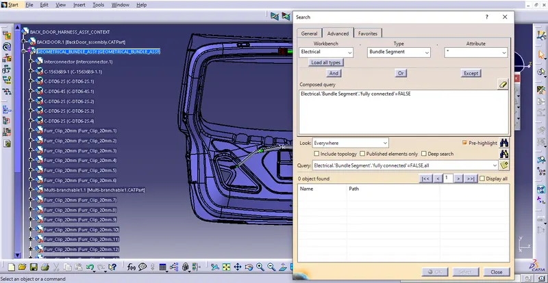
False Condition is reflecting null elements that means there is no bundle discontinuity
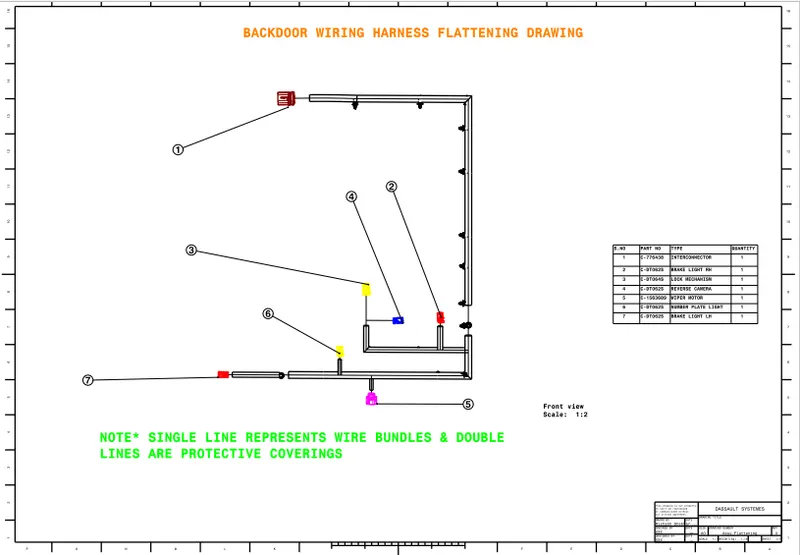
Step 8 , Flattening :
After wiring harness Bundle packaging process is done.We need to convert the geometrical bundle into a flattened wiring harness in the Electrical Harness Flattening Workbench.
- To create the Flattened Harness, we need to create a new product file and switch into the electrical harness flattening workbench.
- Then we need to define the Harness Flattening Parameters and then Extract the geometric bundle from the wiring harness context product file.
- Then select all the branches and flatten the entire Geometric bundle.
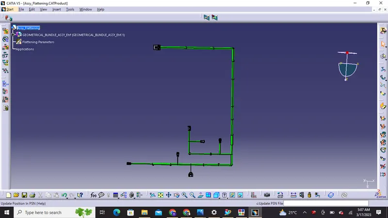
Then we need to rotate the bundles as required
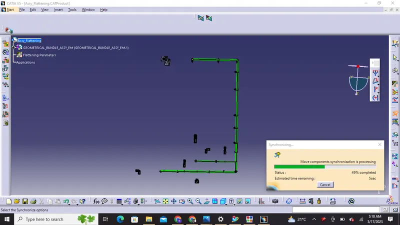
Synchronize is performed after adding protective coverings
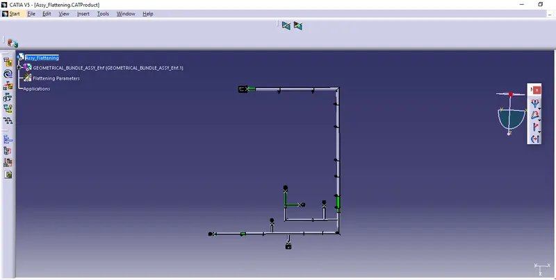
Synchronize updates the flattening assy with respect to geometrical bundle assy
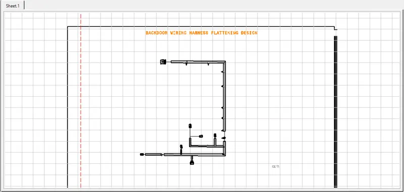
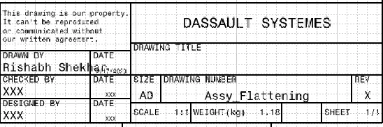
Step 9, Drafting: Finally Preparation of drawing is carried out in drawing workbench
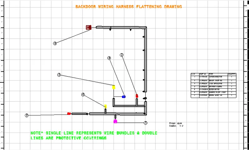
Output:
Thank You!