Project 2
AIM: To route the wiring harness on given car body and flatten view drawing in CATIA V5.
Objective - The objective of the project is to route the wiring harness on given carbody (Backdoor of car) and flatten view drawing in catia v5. All types of packaging rules have to be considered while routing the harness. Also, Industry best practices should be demonstrated in this design. All the necessary details like clearance, clipping/clamping selection, harness fixing requirements, harness continuity should be provided in order to design wiring harness.
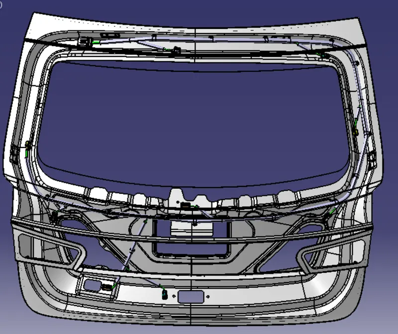
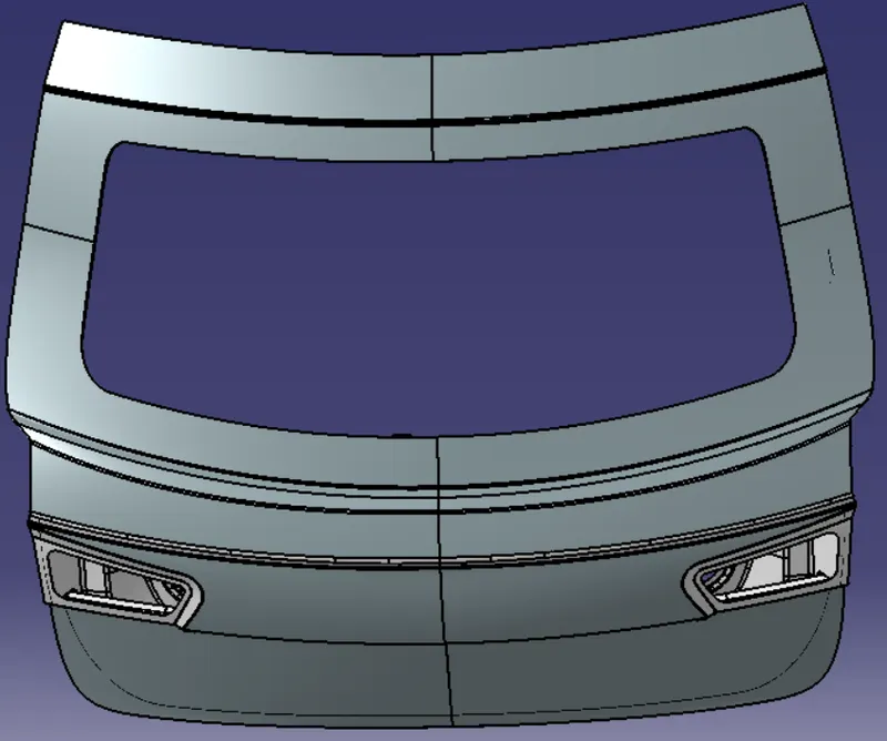
Backdoor car body 3D CAD image
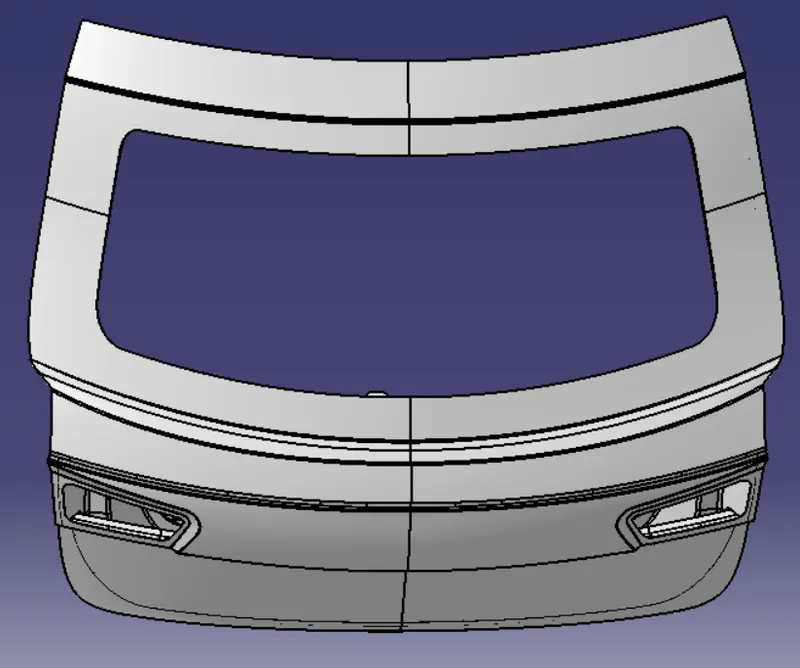
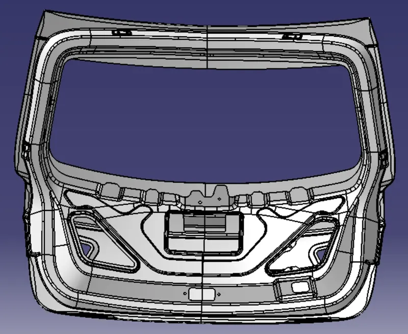
Figure 1: Backdoor 3D CAD car body
Types of Cars
The world of automobiles offers a range of vehicle types, and each comes with its own set of advantages. There are so many type of cars depend on their body's like Hatchback, Sedan, SUV, MUV, Crossover, Minivan, Station wagon, Convertible, Pickup truck, Limousine, Coupe etc.
Sedan : Honda City, Maruti Suzuki Ciaz, BMW 3 series, Toyota Corolla etc
Hatchback : Maruti Suzuki alto, Hundai i10, Tata Tiago, Maruti Suzuki swift etc.
SUV : Toyoto Fortuner, Range Rover, MG Hector, Mahindra alturas, Tata Safari etc.
Coupe: Ford mustang, Audi R8, Mercedes Benz GLE Coupe etc. (A coupe is a two-door car with a sloping roofline)
Station Wagon : Tata indigo Marina, Maruti Baleno altura, Tata estate, Volvo V90 Cross Country etc.
Electric SUV : Tata Nexon EV, Hundai Kona, Mahindra eKUV100, MG ZS EV etc.
Electric Sedan : Mahindra e-Varito, Tata Tigor EV etc.
Electric Hatchback: Mahindra e20 Plus, Mahindra eKUV100 etc.
HATCHBACK:
This type of car is a small car with a rear door which opens upwards revealing the boot space to keep your luggage. Excluding the rear door, hatchbacks are built with four-doors, while two-door hatchbacks are also available in the market. Most hatchbacks use the front-wheel drivetrain to propel the vehicle, while performance-oriented hatchbacks can be either a rear-wheel or front-wheel drive.

In this project, given backdoor source is a Hatchback Car and we have to do harness of backdoor of Hatchback cars.
Backdoor of Car body
A Door is a hinged part which is used for entry and exit of the vehicles. Backdoor are one of the type of door of the vehicle which are located next to the passanger seat which provides access to the luggage compartment. In the most of the cars, these back door are operated with the help of gas stay which in turn reduces the effort required to lift the door.
- This backdoor of carbody consist electrical components as Upper backlight, left hand & Right hand backlight, Wiper motor actuator, Sensor actuator, Camera, Number plate, Defogger etc provided in the backdoor.
- There are 10 connectors need for wiring harness routing in backdoor of Hatchback car.
- Generally high current connectors used for the parent connector just becouse of current follow through this connector is high and all the distribution occurs there.
- Upper backdoor consist 1 connector place for upper side light, 1 connector need for Camera, 2 connector need for defogger, 2 connector need for backlight (LH, RH), 1 connector need for wiper motor actuator, 1-1 connector need for sensor actuator and number plate.
- The bend ratio for all bundle segment should be 1.4.
Some assumptions taken for this project:
- Provide clips/clamps as per requirement.
- Make sure that there is no any fauling case while designing the wire harness. Additional clips/clamps may be used to avoid fauling case.
- Give additional slack if needed. 5-10% slack is sufficient.
- Avoid routing over bolt and bolted joints to avoid harness puncture.
- Avoid routing on sharp edges or else provide protection over the harness.
- Follow the clearance distance and keep away the harness from heat generation components.
- Protection should be provided as needed according to surrounding temperature.
- Branch length should be greater than 50mm.
- Minimum distance between two branch points should be at least 50mm.
- Minimum distance between clip and branch point should be at least 25mm.
- The wiring harness should be easy to assemble and easy to access.
- While using dummy connectors, ensure that whatever positions you are defining that are practical. Bundle diameters and another placements can be defined properly for the wire harness routing.
- If the packaging area is too tight and there are many packaging constraints then we can think of creating harness channel which can be used to route and protect the wire harness effectively.
These are the following steps to do Backdoor wiring harness routing in CATIA V5:
Step 1: Import all the required file for backdoor harness routing like connectors, backdoor, clips and clamps etc.
Step 2: Creating context assembly
- Create a product file and rename this product file as Backdoor Context Assembly.
- A Context Assembly for backdoor harness has created which will work as the main assembly as shown in below figure.
- A Context Assembly will contain Backdoor Assembly data for car body and Backdoor Harness Geometrical Bundle.

Figure 2: Context harness assembly
Step 3: Import all connector in catia v5 and Define all of them as electrical
Here, according to the requirements we are using 12-pole connector. The CAD data downloaded from TE.com. This connector are sufficient enough for flow the current properly in backdoor harness.
These are the following step to define connector as electrical
- Import the file in catia v5
- Switch to the part design workbench
- Define this connector as geometrical parameters
- First bundle entry point, create point on mating side and then create axis on mating side of connector
- Switch to the electrical part design workbench
- Define as a connector
- And then define bundle connection pont and connector connection point
- Save the file
Tyco 12-pole Connector
It is a parent connector where to start routing and it is sufficient enough to manage all the harnesses.
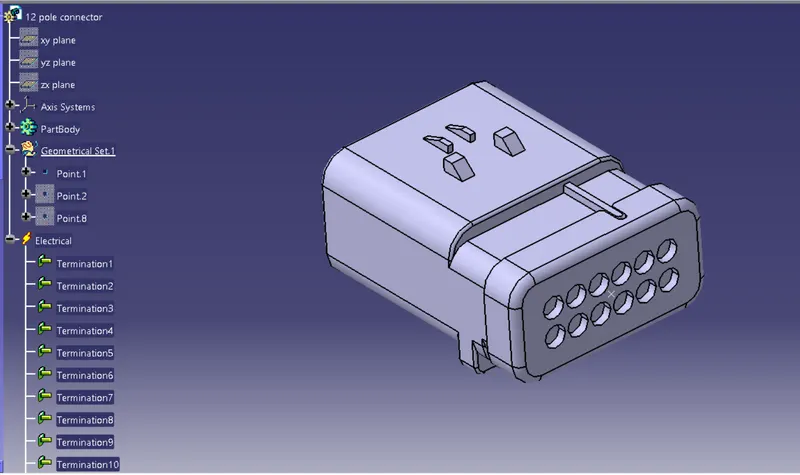
Figure 3: Tyco 12-pole connector
Tyco 4-pole connector
This connector is used for Wiper motor actuator in the backdoor.
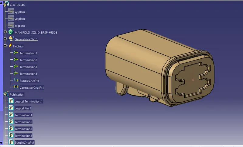
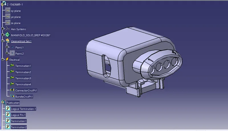
Figure 4: Tyco 4-pole connector
Tyco 3-pole connector
This connector is used in backlight left and right side of the backdoor.
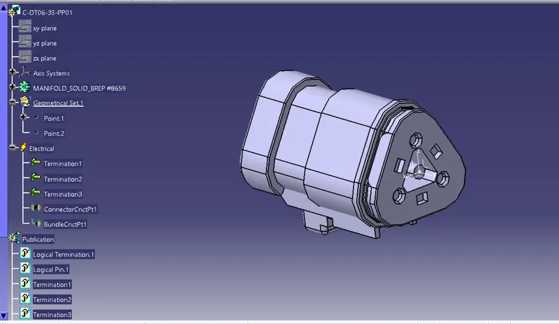
Figure 5: Tyco 3-pole connector
Tyco 2-pole connector
This connector is used for lower side of the backdoor and sensor actuator.
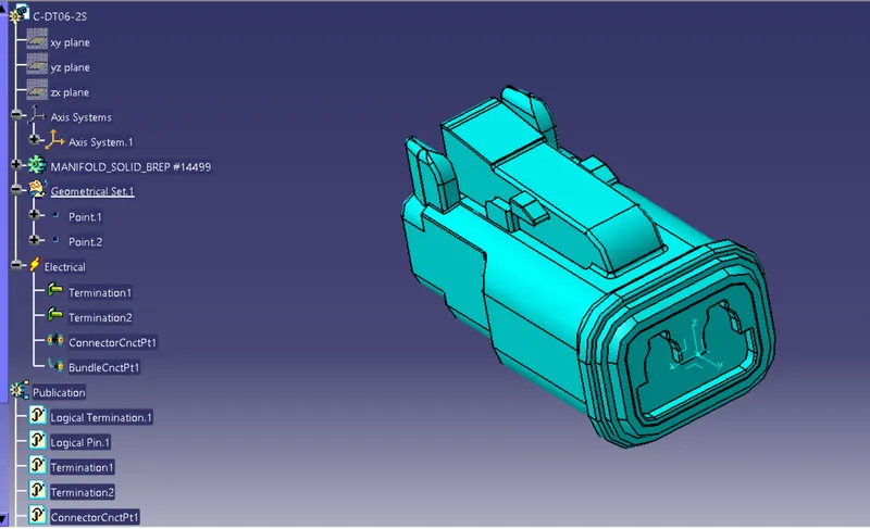
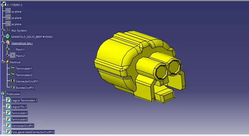
Figure 6: Tyco 2-pole connector
Step 4: Import all the connectors in geometrical bundle assembly in Backdoor context assembly file
In this step, first import the connectors and place all the connectors at desired location like 12-pole connector as parent connector at upper side of backdoor. We have to use manipulation tools along with compass, snap and smart move features to locate all the connectors at their desired locations.
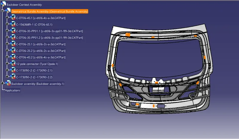
Figure 7: Placing connector at desired location
Step 5 – Placing furr tree clips to the required locations to ensure proper harness routing throughout the Assembly.
- Total 13 furr tree clips need to ensure proper harness routing.
- Ensure no fouling of harness to the back door sheet metal components.
- Enough clamps shall be provided to ensure the positive clearance with surrounding and safety of wiring harness. Distance between two clamps/clips on a straight branch should be maximum of 200mm. However clamping requirements should be decided based on the harness bending and mounting arrangements.
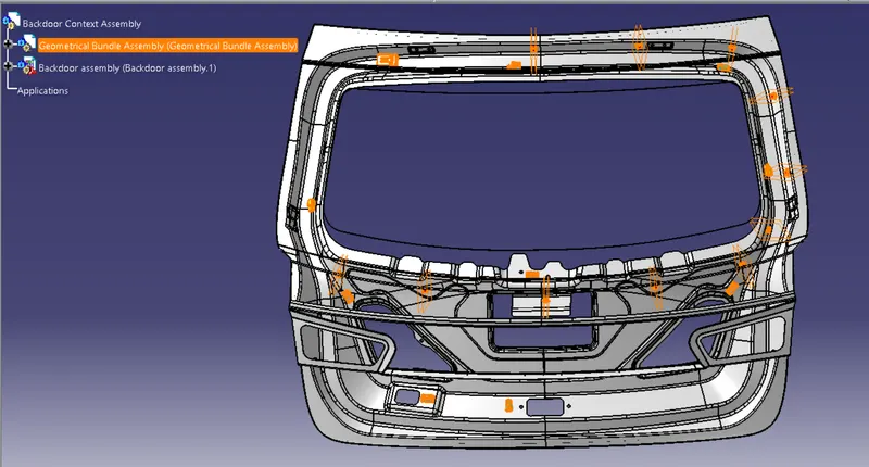
Figure 8: Placing furr tree clip at desired location
Step 6 - Wiring Harness Routing
- Now, the car tail gate assembly is ready for the bundle routing as shown in above figure 8.
- We have activated Geometrical bundle product file from the context assembly to create new multi-branchables.
- Add branch points at minimum of 25mm distance from clips and clamps to create new sub branches connecting various connectors.
- Minimum length of bundle should be 50mm.
- First, we have started bundle routing from interconnection (parent) connector to the nearest Mounting clip available and the continue to add multibranchabe bundles to achieve the required harness bundle. Main bundle harness diameter is considered as 10mm.

Figure 9: Routing from interconnection connector
- Now create branch point to route sub bundle to the Top mount brake light connector to ensure proper and safe routing. Bundle diameter is considered as 5 mm. Reference length from the furr tree clip should be minimum 50mm.
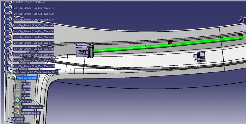
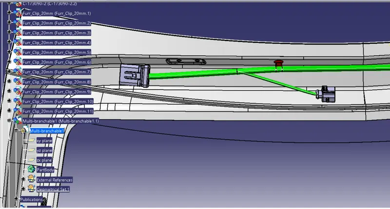
Figure 10: Routing top mounted brake light
- Extend main bundle segment and add branch point to create sub-bundle connection towards the Cam connector (Camera).
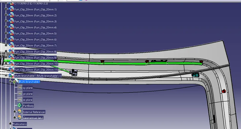
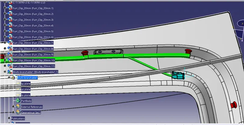
Figure 11 : bundle connection for CAMERA
- Add branch point to create bundle connection towards the defogger connector but when extend the main bundle segment (10mm) so at the corner of the tailgate give 5% slack first then extend towards defogger connector. And create a sub-branch and make connection between main bundle and defogger connector. This sub-branch bundle should be less than main bundle like here i take 5mm for the defogger connector.

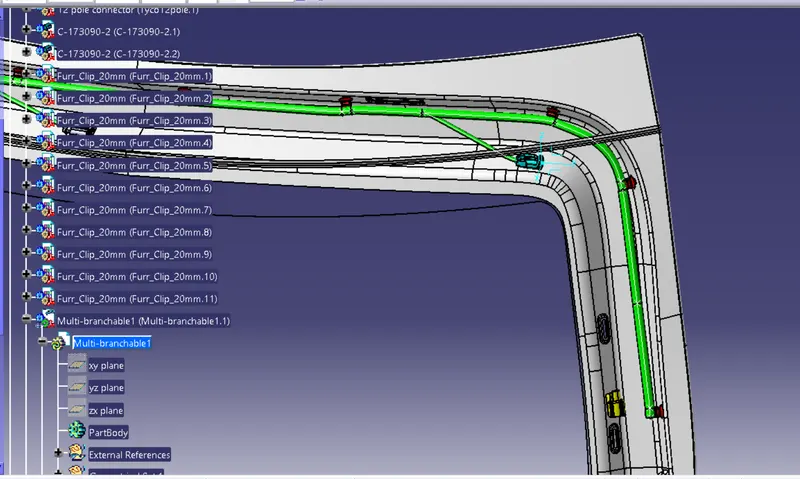
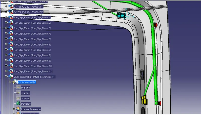
Figure 12 :Routing for Right side defogger connector
- Now extend main bundle segment towards the back light and viper motor actuator. Add a branch point for the back light of the tailgate and make a bundle connectionbetween back light and main bundle segment. keep main bundle segment 10 mm diameter and 5 mm diameter for sub-branch.
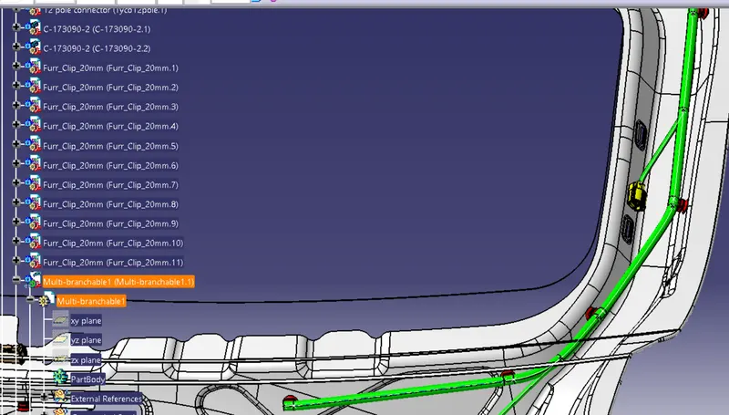
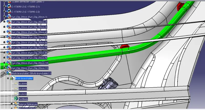
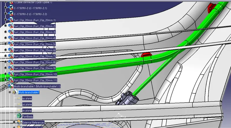
Figure 14: Routing for right side back light
- Now we do routing in wiper motor actuator with extension of main bundle segment and their sub-branch between bundle segment and wiper motor connector. for that main bundle segment dia is 10mm and branch dia is 5mm.
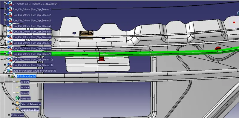
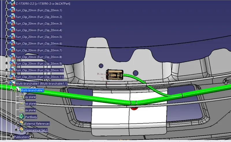
Figure 15: Routing for Wiper motor actuator
- Route for the second defogger connector with sub-bundle of main bundle segment (5mm) and add branch point on the bundle and make the bundle connection between bundle and Left Side Backlight connector with bundle diameter 5mm.
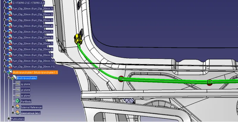
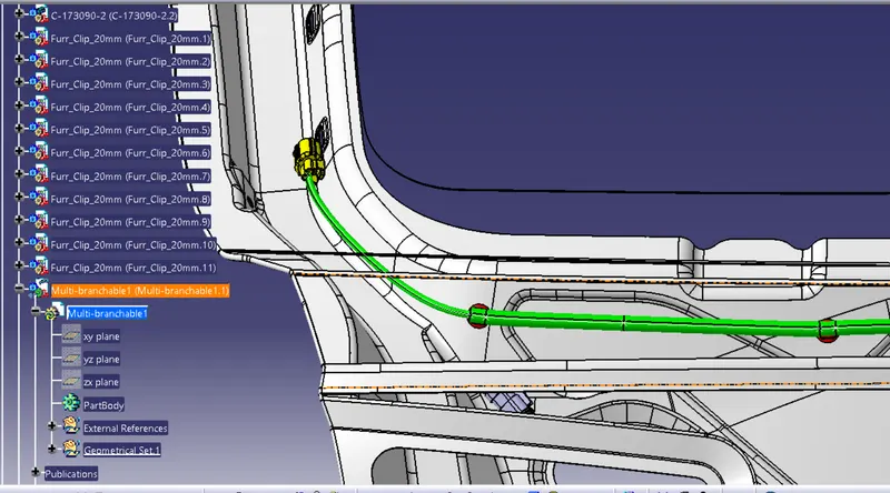
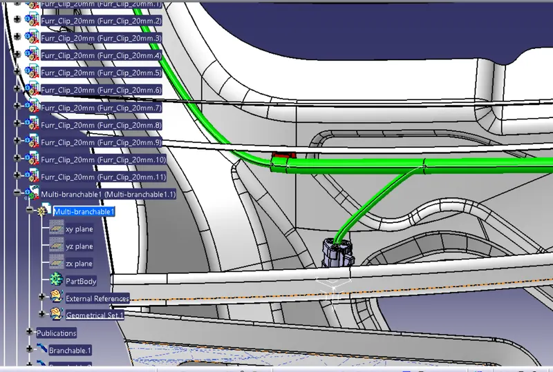
Figure 16: Routing for left side defogger and backlight connector
- Now create a branch point inbetween wiper motor connector and left hand backlight connector. And route for sensor connector and buttom side number plate backlight connector and make sure sub-branch bundle diameter is 5mm.
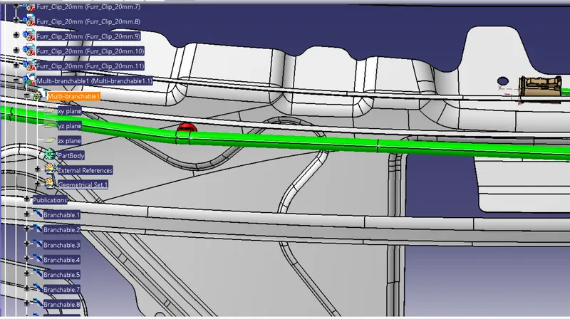
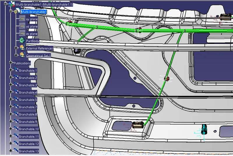
Figure 17: Routing for sensor connector
- Now the last routing for number plate. create a branch point between sub-bundle of sensor connector and route from that branch point.
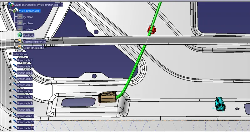
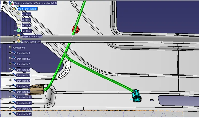
Figure 18 : Routing for Number plate connector
Final geometrical bundle assembly
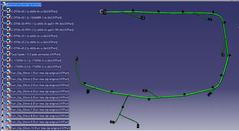
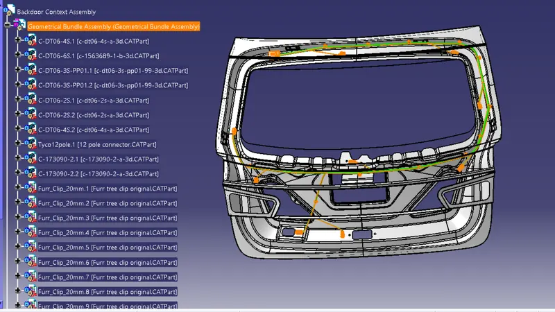
Figure 19: Geometrical bundle assembly
Step-7: Applying Protective Cover
After bundle routing, we have to add protective covering to the harness bundle so that it will get protected from the damage.
- Harness bundle should be protected with flexible rubber cover at the interconnection region where it is a critical place and subjected to opening and closing of door. There are more possibilities to damage the wiring harness if no proper protection covering is provided.
- Corrugated conduits and protective hoses with various properties, from heat resistance through abrasion protection and impact strength to noise reduction, protect valuable cables against all unfavourable external influences.
- Slit COT tubes are provided for protecting the harness from physical and other environmental damages that can occur in the long run.
- Start or End Extrimities at the Connector bundle entry side should be given a gap of 30mm
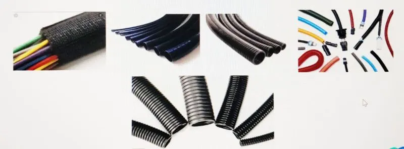
Figure 20: Corrugated tubes
- Selection of corrugated tubes are mainly driven by the wiring harness bundle diameter and temperature resistance requirements.
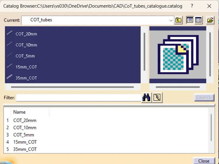
Figure 21: Corrugated tubes with their dimension
Now to start adding corrugated tube on bundle segment according to their diameter like for 10mm diameter of bundle segment so for that 12 to 15mm corrugated tube can be applied and for 5mm bundle segment corrugated tube must be use atleast 8 to 10mm.
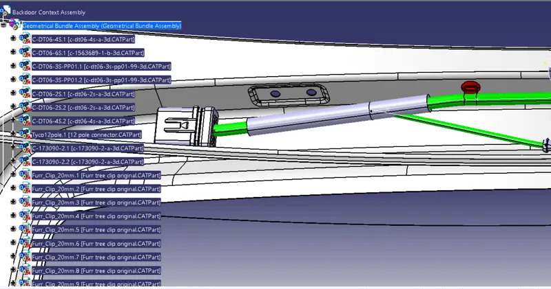
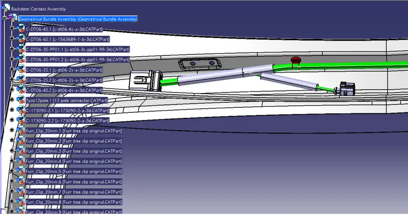
Figure 22: Applying corrugated tubes on bundle segment
Geometrical bundle after applying corrugated tube
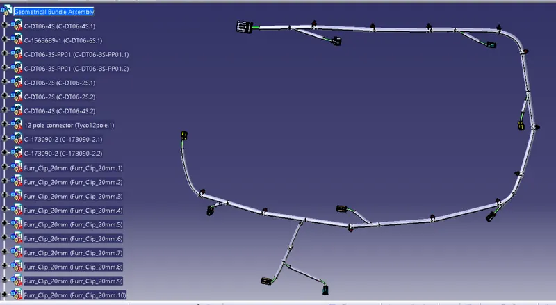
Figure 23: Fully covered bundel segment by corrugated tube
Step 8 - Electrical Continuity Check
We need to ensure that the entire bundle is fully connected.
- Go to edit and then click on search command.
- Go to advanced
- Select workbench as electrical, type as bundle segment and attribute as Fully connected
- The select result should be as TRUE or FALSE and the click search to see the connectivity analysis result
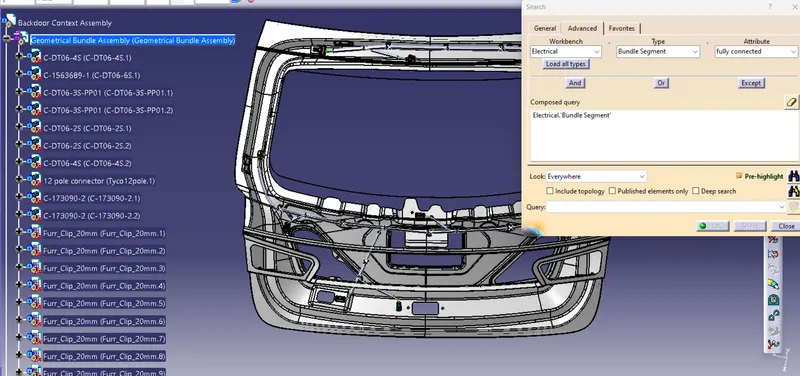
Figure 24: Checking bundle continuity
- For now, we will select "TRUE" and search for results. All the bundle segments are highlighted and found showing that all the bundle segments are electrically connected.
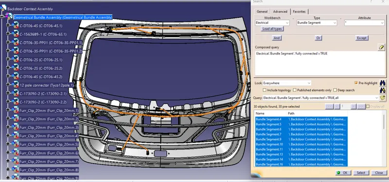
Figure 25: Checking TRUE bundle continuity
- Here, applying FALSE connection we will see that the bundle segment is linked perfactly and no errors are detected.
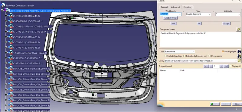
Figure 26: Checking FALSE bundle continuity
Step 9 - WIRING HARNESS FLATTENING
Wiring harness Bundle packaging process is done. Now we need to convert the geometrical bundle into a flattened wiring harness in the Electrical Harness Flattening Workbench.
- To create the Flattened Harness, we need to create a new product file and switch into the electrical harness flattening workbench.
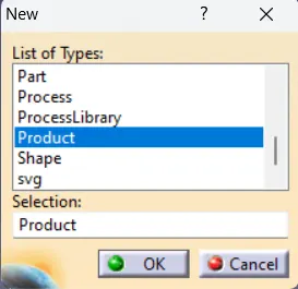
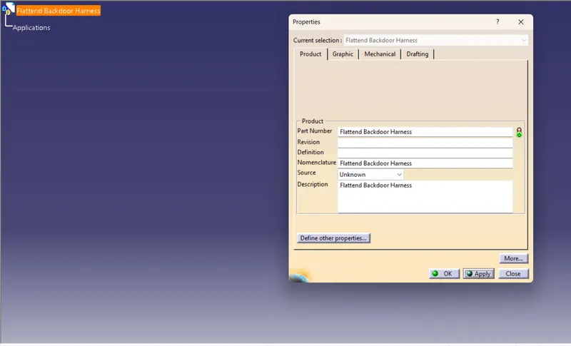
Figure 27: Flatten product file
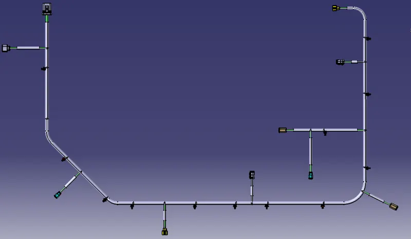
- Now we need to define the Harness Flattening Parameters, save it in the same folder with all other files of back door harness project and then Extract the geometric bundle from the wiring harness context product file.
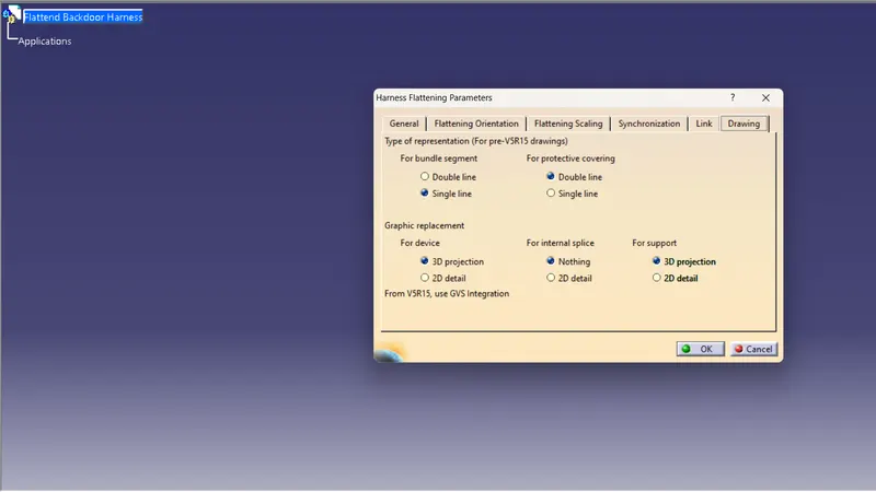
Figure 28: Flattend parameter
- When we extract geometrical bundle assembly This file change into EHF file (Electrical harness flattening) as we can see in below image.
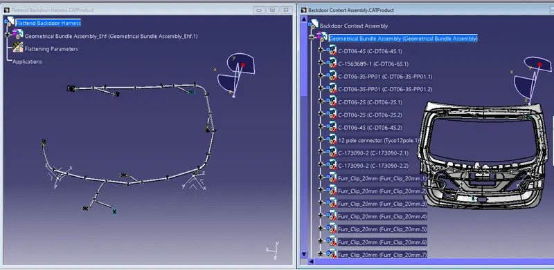
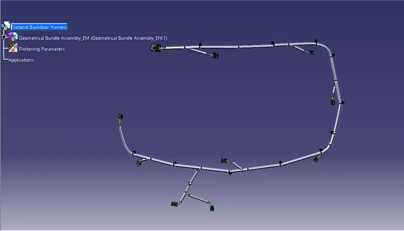
Figure 29: Import geometrical bundle
- Then select all the branches and flatten the entire Geometric bundle.
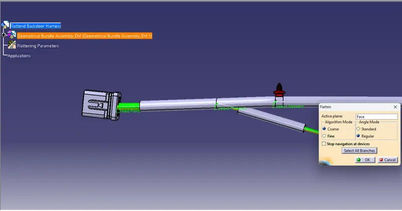
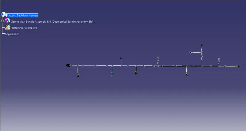
Figure 30: Flatten view
- The bundles can be rotated and rolled with a proper radius in order to fit the drawing sheet.
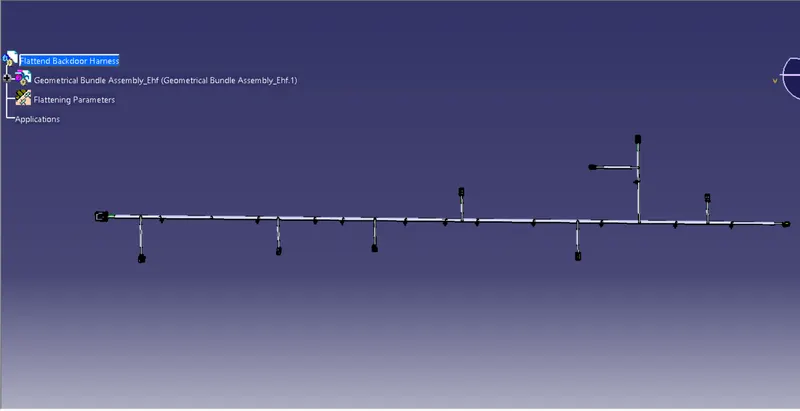
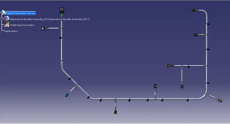
Figure 31: Rotate flatten to fit in drawing sheet
Step 10 – Flattened Harness View In The Drawing Sheet
Create a Drawing File for the flattened harness product.
First, we need to make sure that in the flatten parameter settings bundles and protective coverings have different graphical representation which are
Bundle Segments – Single line representation
Protective coverings – Double line representation.
- Create a new drawing file in the drafting workbench
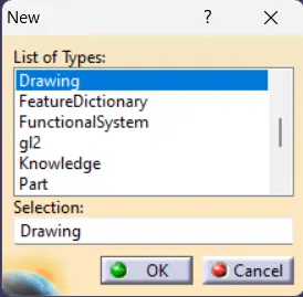

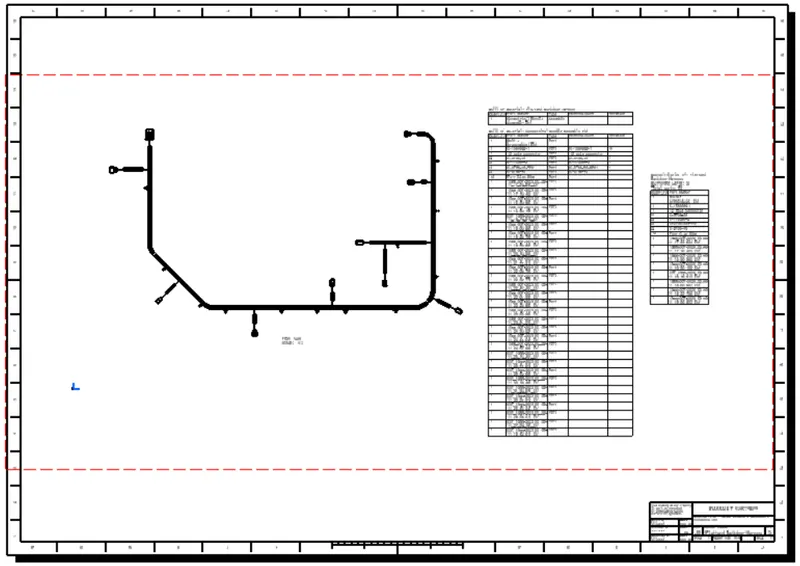
Figure 32: Drawing sheet
- Insert the flattened harness product into the drawing sheet using view option and selecting the front view command.
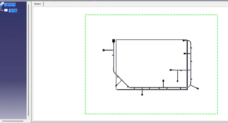
Figure 33: Importing flatten view in drawing sheet
- Modify the drawing sheet view with required parameters.
- Click on the red boundryline of flatten assembly
- Go to the property and then View
- Now go to the view>scale and orientation - scale (1:3) and
- View> Dress-up> Filter> Boundries> 3D wireframe> is always visible (select all the command)
- Click on apply> OK.
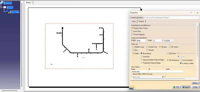
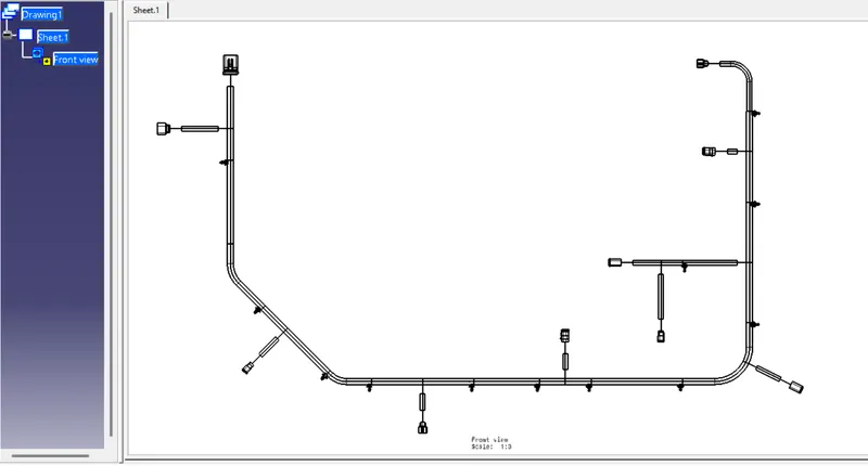
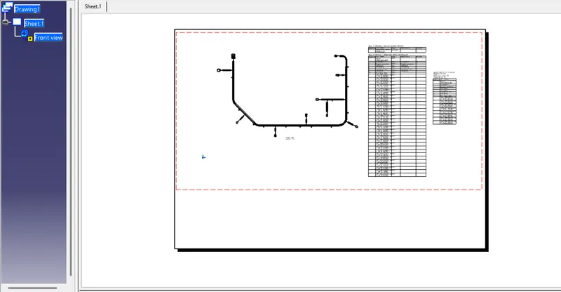
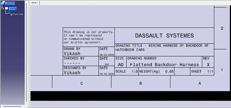
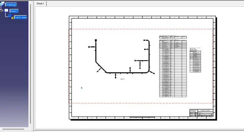
Figure 34: Drawing view of Backdoor Harness Flatten view with bill of material and project title
CONCLUSION
CAR backdoor wiring harness assembly has been successfully completed considering all the packaging rules and industry standards, Wiring harness flattening and Flattened view drawing preparations are also done using CATIA V5 software.