Project 2
Q1). Design a Warehouse Building located in Chennai using STAAD Pro Connect Edition. The specification must be as follows:
|
Width |
30m |
|
Length |
50m |
|
Eave Height |
9m |
|
Bay spacing |
6m |
|
Soil type |
Medium |
|
Safe Bearing Capacity |
200 kN/m2 |
|
Roof slope |
1 in 12 |
Assume suitable sections for structural elements. Follow IS800:2007, IS1893 and IS 875
- Prepare a Design Basis Report for the project
- Create structural model using STAAD Pro Connect Edition
- Prepare DL, LL, WL and EQL load calculations as per IS 875 standards
- Design using MS – Excel
- Steel column
- Rafter
- Base plate
- Pedestal
- Z- purlin
- Design Foundations using STAAD Foundation.
- Attach necessary sketches and drawings wherever required.
- All stipulations, assumptions and design parameter must adhere to Indian Standards.
Answer:
AIM:
Design a Warehouse Building located in Chennai using STAAD Pro Connect Edition
- Prepare a Design Basis Report for the project
- Create structural model using STAAD Pro Connect Edition
- Prepare DL, LL, WL and EQL load calculations as per IS 875 standards
- Design using MS – Excel
- Steel column
- Rafter
- Base plate
- Pedestal
- Z- purlin
- Design Foundations using STAAD Foundation.
- Attach necessary sketches and drawings wherever required.
- All stipulations, assumptions and design parameter must adhere to Indian Standards.
INTRODUCTION:
To create a model by using data and apply loads dead loads live loads,wind loads
- Section 7 of IS 800:2007
- Buckling class
- Effective length of column
- Cross sectional shapes(Built up columns).
Web buckling:
- Web buckling occurs when intensity of compressive stress near the center of the section exceeds the critical buckling stress of web acting as a strut.
- at supports and under a concentrated load certain portion of the beam acts as a column to transfer the load.
- Under this compressive force the web of the beam section may buckle.
-
Limit state of strength:
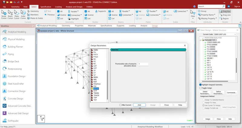
- Limit state strength are those associated with failures under the action of probable and most unfavorable load combinations on the structure using partial safety factor.
- The might endanger the safety of life and property.
- Checked by utilization ratio.
Limit state of serviceability:
- Limit state of serviceability are those associated with deformation and deflections which may adversely affective use of the structure.
- Checked by deflection limits.
PROCEDURE:
ROOF SLOPE CALCULATION:
Roof Slope = 1 in 12
Width, b = 30 m
X/(b/2) = 1/12
X = (30/2) / 12 = 15/12
X = 1.25 m
GEOMETRY / MODEL CREATION:
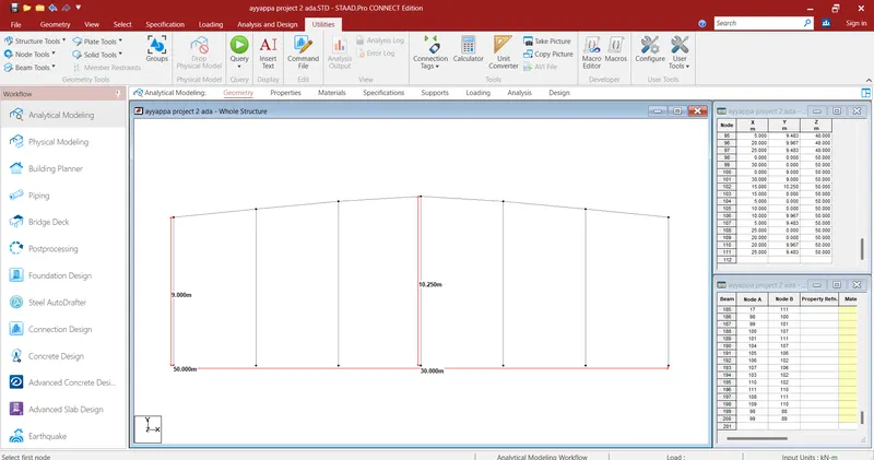
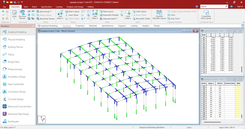
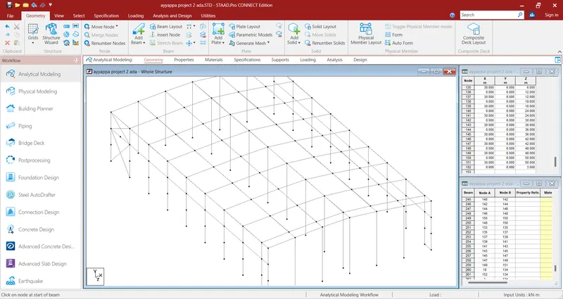
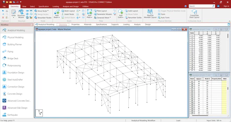
PROPERTIES:
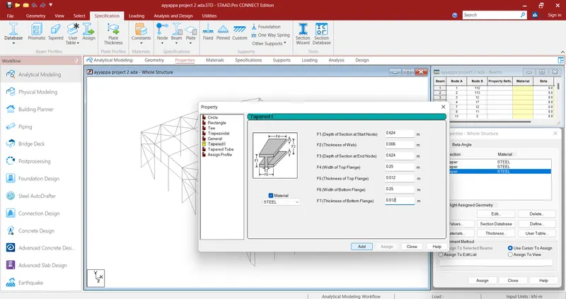
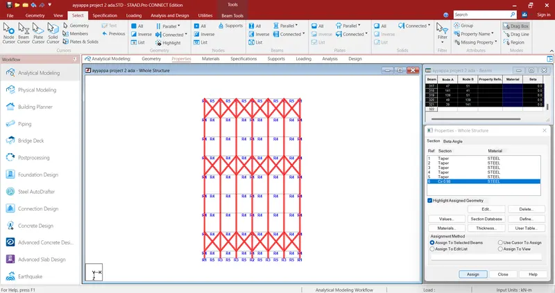
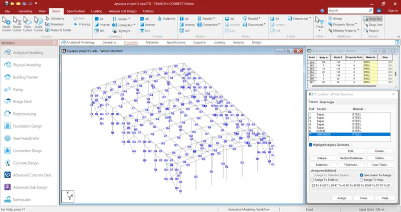
3D VEIW OBJECT:
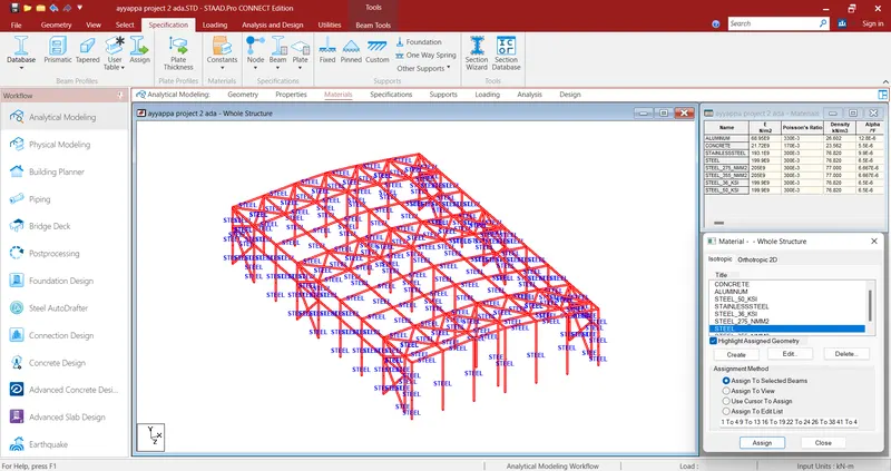
Material: STEEL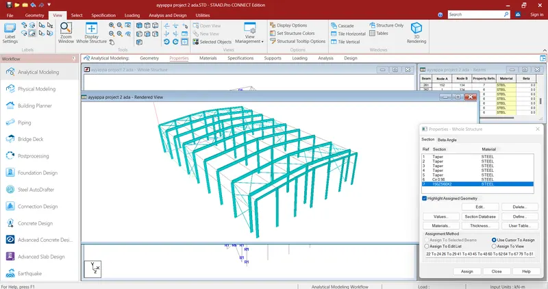
BETA Angle 90 degree for wind / gable columns
Materials:
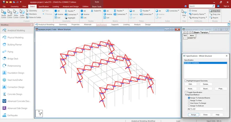
SPECIFICATION:
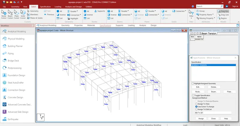
- Member Tension
- End MY MZ
- Start MY MZ
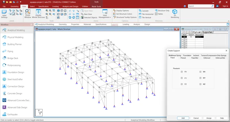
SUPPORT:
- Pinned
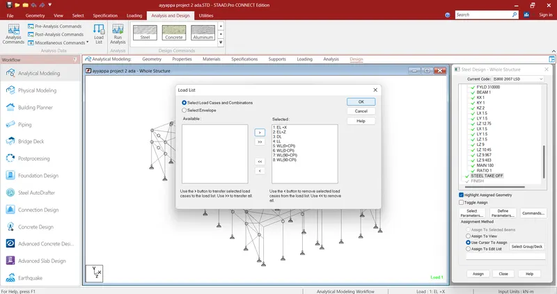
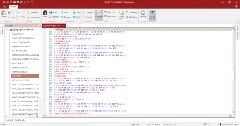
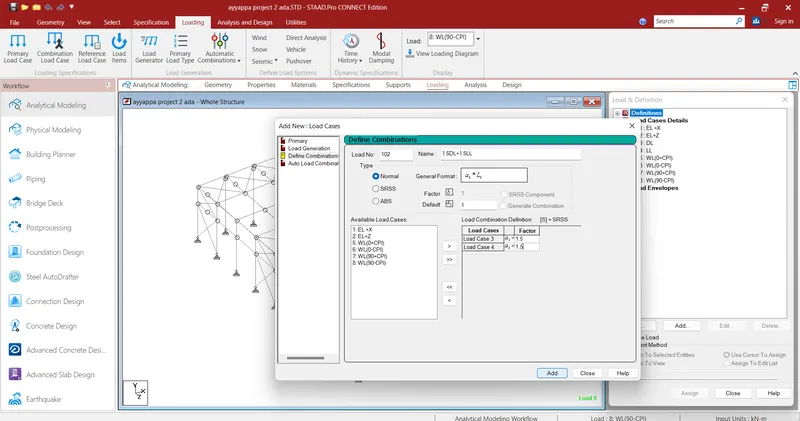
LOAD CASE DEFINATION:
1. EQ+X
- IS 1893 Load-X 1
2. EQ+Z
- IS 1893 Load-Z 1
3. DEAD LOAD
- Self weight Y -1.15
- Main frame rafter GY -1.55 KN/m
- Gable frame rafter GY -0.775 KN/m
- Main frame column GY -1.2 KN/m
- Gable frame column GY - 0.6 KN/m
- Gable / wind column GY -1.04 KN/m
- Wind frame point load FY - 1.14 KN/m
- Gable frame point load FY -0.57 KN/m
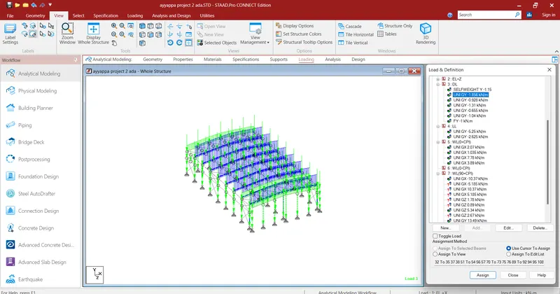
4. LIVE LOAD
- Main frame rafter GY -4.85 KN/m
- Gable frame rafter GY - 2.425 KN/m
- Wind frame point load FY - 4.15 KN/m
- Gable frame point load FY - 2.06 KN/m
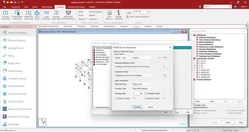
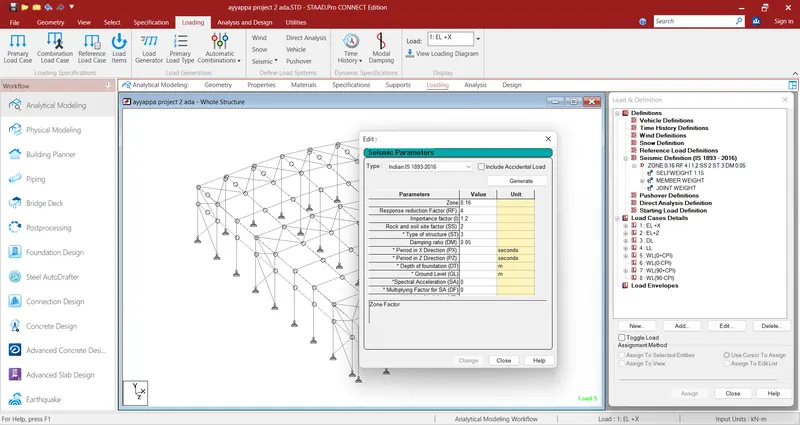
SEISMIC DEFINATION:
Zone Parameters:
Member Weight:
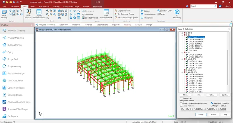
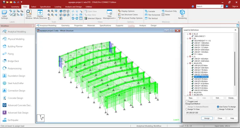
Assign to Edit list from followed by the Dead Load
- Self weight Y -1.15
- Main frame rafter GY -1.55 KN/m
- Gable frame rafter GY -0.775 KN/m
- Main frame column GY -1.2 KN/m
- Gable frame column GY - 0.6 KN/m
- Gable / wind column GY -1.04 KN/m
Joint Weight:
Assign to Edit list from followed by the Dead Load (point load)
- Wind frame point load FY - 1.14 KN/m
- Gable frame point load FY -0.57 KN/m
LOAD CASE DEFINATION:
5. Wind load (0+CPi)
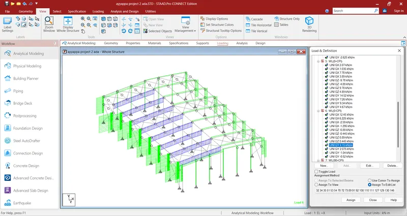
6. Wind load (0- CPi)
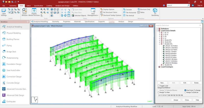
7. Wind load (90+CPi)
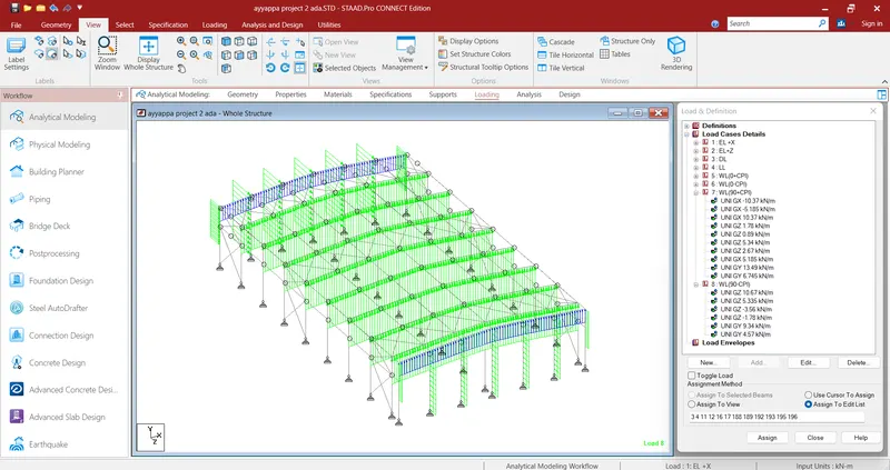
8. Wind load (90- CPi)
DESIGN OF STEEL COLUMN:
Solution:
Flange thickness = T = 12.7 mm.
Overall height of Column ISMB400 = h = 400 mm.
Clear depth between flanges = d = 400 – (12.7 x 2)
= 374.6 mm.
Thickness of web = t = 10.6mm.
Flange width = 2b = bf = 250 mm.
Hence, half Flange Width = b = 125 mm.
Self –weight = w = 0.822 kN/m.
Area of cross-section = A = 10466 mm2.
Radius of gyration about x = rx = 166.1 mm.
Radius of gyration about y = ry = 51.6 mm.
Step - 1
Type of section:
Properties of selected section
ISHB 400.
Flange criterion b/T = 125/12.7= 9.8 < 10.5
Web criterion d/t =374.6/10.6 =35.3 < 42
(Table 3.1 of IS: 800)
Hence, cross-section can be classified as “COMPACT”.
Step - 2
Effective Length:
As, both ends are pin-jointed
Effective length, KLx =9m
KLy = 9m
KLz = 9m
Slenderness ratios:
KLx/rx = 9000/166.1 =54.1
KLy/ry = 9000/51.6 =174.41
Non-dimensional Effective Slenderness ratio
λ">λ = 1.96
Step - 3
To calculate φ:
h/bf = 1.60
>1.21
T = 12.7mm
so buckling class = b
= 0.34
φ= 0.5(1+(λ-0.2)+λ^2)
= 2.76
Step - 4
Calculation of x from equation x:
= 0.214n/mm^2
Step - 5
Calculation of fcd :
fcd = Xfy/γm
= 49.15
Step - 6
Factored axial load :
pd = Afcd
= 514.61 kN.
DESIGN OF RAFTER:
Solution:
Span of Rafter = 6 m
Dead load = 18KN/m
Imposed load = 40KN/m
support bearing = 100mm
yield strength = 250N/mm2
Step - 1
Design load calculation:
Factores load 1.5(DL+LL) =87 KN/m
Factored Bending moment = 391.5 KN/m
Step - 2
Section modulus Required:
Z reqd = 1722600mm^3
= 1722.60cm^3
Step - 3
Section classification:
Flange criterion B/2T = 5
Web criterion (D/2T)t =32.61
ɛ=1
B/2T<9.4
(D/2T)t<83.9
The section is plastic.
ISMB-250
A = 475.5mm2
D = 250mm
B = 125mm
t = 6.9 mm
T = 12.5 mm
Izz = 5131.6cm^4
Iyy = 344.5 cm^4
Zp = 459.76 cm^3
Flange section B/2T = 5
Web criterion(D-2T)t = 32.61
B/2T<9.4
(D-2T)/t<83.9
The section is classified as plastic.
Step - 3
Moment of resistence of the cross-section:
Md = (zp X fy)/γm
Md = 1044.491 KN/m
<391.50
Hence section ISMB 250 IS Adequate for flexure.
Step - 4
Shear resistance of the cross section:
Shear capacity Vc = 0.6fyAv/γm
Av = 1725mm^2
Vc = 235.23kn
V= 261kn
V/Vc = 1.11
>0.6
Step - 5
Check for web buckling:
Slenderness ratio of web = 2.5d/t
d = 225mm
Design compressive stress fc = 203N/mm^2
Pw = 315.16kn
>261
Hence web is safe against shear buckling.
Step - 6
Check for web crippling at support:
Root radius of ISMB250 R = 13mm
tf + R =25.5mm
Dispersion length n^2 = 63.75mm
Pcrip = 245625N
=245.63kn
<261
Hence section adequate for web crippling.
Step - 7
Check for serviceability deflectio:
Design load = 58kn/m
Deflection = 95.36
Allowable deflection = 30mm
Hence serviceability is satisfied
DESIGN OF BASE PLATE:
Step -1
Strength of concrete, Fcu = 40 N/mm2
Yield strength of steel, fy = 250 N/mm2
Material factor, γm">γmγmFA−6XMzBL2= 1.1 KN
Factoresl oad = 1500 KN
Step - 2
Steel column section:
Thickness of flange, T = 12.7 mm
Step - 3
Area required:
Bearing strength of concrete = 0.4fcu = 0.4 x 40 = 16 N/mm2
= (1500x1000) /( 16)
= 93750 mm2
Let size of plate , Bplate = 350 mm
Dplate = 350 mm
Area of plate= 122500 mm2
projection on each side = a=b =25mm
W = (1500x1000) /( 450 x 300)
= 11.11 N/mm2
Therefore, Thickness of Base Plate, clause 7.4.3.1
LXσ1σ1+σ2
ts= 7.7 mm < 12.7 mm
Size of Base plate 350mm x 350mm x 12mm
d) DESIGN OF PEDESTAL:
Grade of concrete = 40 N/mm2
Load = 123 KN
Moment = 116 KNm
Horizontal shear = 13 KN
Yield strength = 250 N/mm2
Length of base plate = 450 mm
Width of base plate = 350 mm
C/C distance of bolt in group-Z = 300 mm
C/C distance of bolt in group-X = 180 mm
Bearing strength of concrete Fc = 16 N/mm2
Depth of Column = 300 mm
Width of Column = 250 mm
Anchor Bolt Details:
Step -1
Dia of anchor bolts =24 mm
No:of anchor bolts in each side = 4
Total no:of anchor bolts, n = 8
Gross area of the bolt ;Asb' = 452.16 mm2
Net area of bolt 'Anb' = 352 mm2
Ultimate tensile strength of bolt 'fub' = 400 N/mm2
Fyb (anchor bolts) = 240 N/mm2
Step - 2
Base plate Details
Ultimate tensile strength of plate 'fu' = 490 N/mm2
Thickness of plate = 16 mm
Yield stress of plate = 330 N/mm2
Step - 3
Anchor bolt design
Area of the plate = 157500 mm2
Stress, Maximum pressure =F/A+6 X Mz/BL^2
= 10.6 N/mm2 < 16 Hence OK
Minimum pressure =F/A-6 X Mz/BL^2
= -9.04 N/mm2 < 16 Hence OK
Centroid = = 242.89 mm
a =L/2-C/3 = 144.04 mm
e = (L-Ld) / 2 =75 mm
y = (L - C/3-e) = 294.04 mm
Tension in anchor bolt along the length of plate, FT = (Mz - Fa)/Y
= 364.38
Tension per bolt = 91 KN
Shear per bolt = 1.63 KN
Step - 4
Shear Check
Factored shear force = Vsb = 1.63 KN
Vd,sb = 81290.9 N
= 81 KN
Factored Vd,sb = 65.03 KN
Step - 5
Tensile Check
Factored tensile force in bolt, Tb = 91.1 KN
Tensile strength of bolt Td,b = Tn,b /γmb">γmb= 126 KN
Td,b = 98.65 KN
Step - 6
Combined Unity Check
Vsb/Vdb = 0.025
Tb/Tdb = 0.92
Unity check = 0.85 < 1, Hence OK
Step - 7
Anchor Bolt Length
Bond strength in tension, τbd">τbd= 1.4 N/mm2
Anchor length required = Tb(3.14*τbd">τbd)
= 863.44 mm
Let Anchor Bolt Length = 900 mm
DESIGN OF Z-PURLIN:
Step -1
Span of the purlin = 7 m
spacing of purlin = 1.5 m
No:of sag rods = 1
slope of the roof = 4.76 = 5 degree
Step - 2:
Dead load:
Weight of sheeting = 5kg/m2
self weight of purlin = 4.22 kg/m2
Additional load = 10% = 0.42 kg/m^2
Total Dead load = 0.096 kn/m2
Live load:
Live load on roof = 75 kg/m2
Wind Load:
Basic wind speed = 50 m/s
Terrain caterogy = 2
Building class = B
K1 = 1
K2 = 1
K3 = 1
Design wind speed, Vz = 57 m/s
Design wind pressure, Pz = 1949.9N/m^2 = 1.94 KN/m^2
Length of building, L = 50 m
Breadth of building, W = 30 m
Height of building, H = 10.5 m
Height of eaves, = 9 m
h/w = 0.34
L/w = 1.67
External Pressure Co-eeficient:
Maximum downward =Cpe = -0.4
Maximum upward =Cpe = -0.7
Internal Pressure Co-eeficient:
Maximum positive =Cpi = 0.5
Maximum negative =Cpi = -0.5
For Maximum upward wind force:
Max upward Cpe = - 0.7
Cpi = - 0.5
Cpe+Cpi = -1.2
Pz = 1.95
Wind Pressure for Purlin Design = - 2.339 KN/m2
For Maximum upward wind force:
Max upward Cpe = - 0.4
Cpi = - 0.5
Cpe+Cpi = -0.1
Pz = 1.95
Wind Pressure for Purlin Design = 0.195 KN/m2
Step - 3
Design Load Calculation:
spacing of purlin 1.5 m
slope of roof = 5degree
Total dead load = 0.096KN/M^2
DL Normal component = 0.144 KN/m
DL Tangential component = 0.013 KN/m
Total Live load = 0.75Kn/m^2
LL Normal component = 1.121 KN/m
LL Tangential component = 0.098 KN/m
Total Wind load = -2.339
WL Normal component = - 3.496 KN/m
WL2 WL load = 0.195 KN/m
WL Normal component = 0.291 KN/m
Maximum Normal component = DL+LL = 1.265 KN/m
Purlin section:
Selected section Z X 200 x 6 x 2.3
Yield stress of material=2400kg/cm^2
Flange width b =60mm
Depth of section d =200mm
Thickness t=2.30mm
Length of lip lip l = 20mm.
Internal bending radius = 3mm
Area = 8.07 cm2
Zxx = 47.72cm^3
Zyy = 10.22cm^3
lxx = 477.18cm^4
lyy = 61.34cm^4
Weight of purlin = 6.335 kg/m
Check for basic properties:
t = 2.30mm
w = 49.40mm
Fy = 2400kg/cm^2
W/t = 21.48
<60
OK
Check for stress:
Span major axis = 7m
Span minor axis = 2m
BM coefficient for mxx = 10
BM coefficient for myy = 10
Maximum compressive stress = 344.80N/mm^2
1435/sq.root of f = 24.44
>21.48
Hence section OK.
Check for deflection:
Number of spans = 3
Deflection = (3/384)(wl^4/EI)
W= 3.351Kn/m
Span = 6m.
E = 207400N/mm^2
lxx = 477.18cm^4
δ = 34.29mm
Allowable deflection δ = Span/180
= 33.33mm
>34.29
Not Ok.
Foundations using STAAD Foundation.
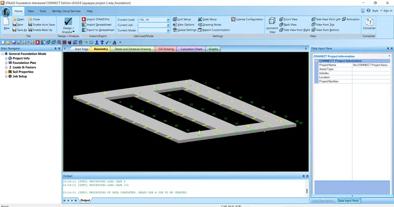
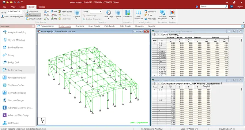
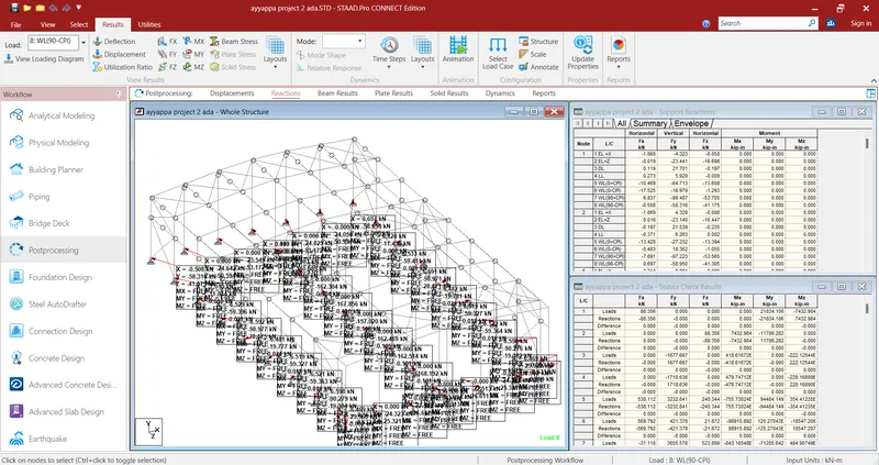
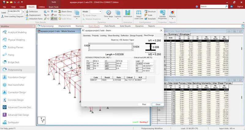
RESULTS:
PROPERTIES:
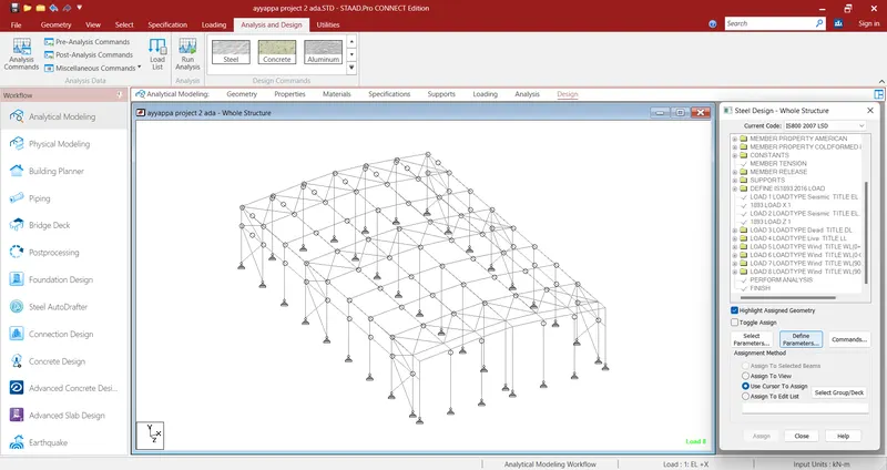
- First you must Analyze the file.
- Select Analyze from the Staad.Pro top menu bar.
- Select the Analysis option. After this, click on Run Analysis at the bottom of the small window dialog box.
- After the analysis of the file is completed, click on the Done button.
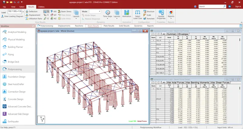
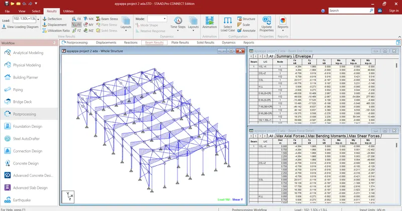
- Next, we go to the Post Processing mode to view the forces and results graphically.
- To enter into the Post Processing mode, select Mode from the top menu bar and select Post Processing.
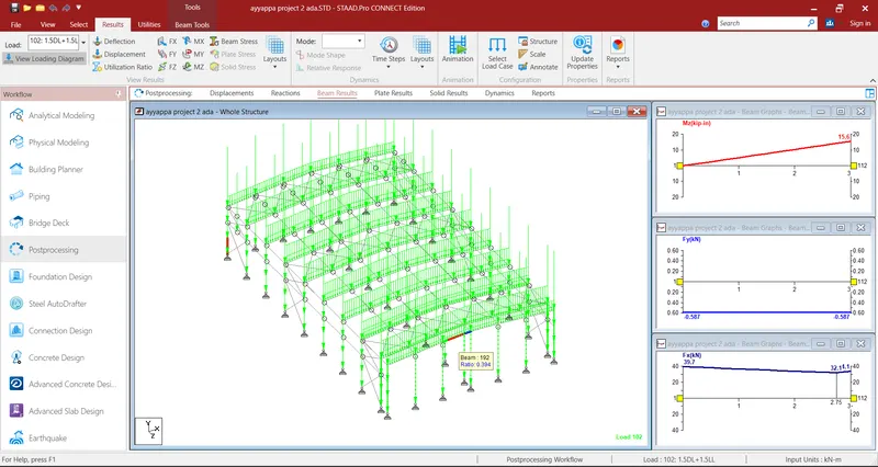
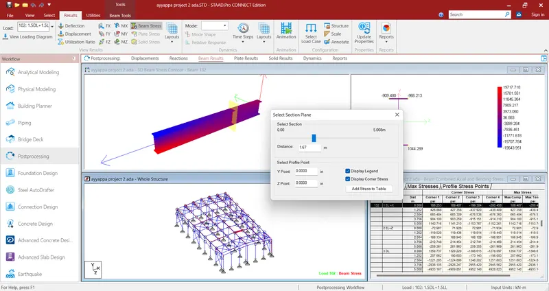
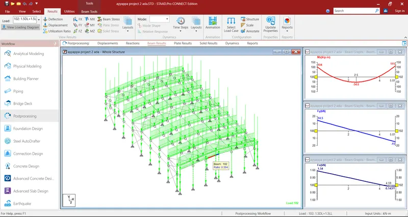
- To view the Bending Moment Diagrams, select the Beam page from the left side. From the top menu bar, choose Results.
- Under the Beam Results tab, you will see the options Bending, Shear, Axial, Displacement and Stresses.
- Click on the Annotate button. Then click on the close button.
- Here are a group of of other options to view BMD, SFDs
- To view the bending moment diagram for individual members you may go to the Beam > Graphs page on the left and click on any member and the BMD, SFD and axial force diagrams for the member would be displayed on the right.
- Alternately you may also double click on any member to bring up the query box and go to the Shear Bending tab to see the bending moment or shear force diagrams for that member.
Q2). Design a simply supported gantry girder to carry electric overhead travelling crane
Answer:
Given that:
Step - 1
Span of gantry girder = 7 m
Span of crane girder = 9 m
Crane capacity = 250 kN
Self-weight of trolley, hook, electric motor etc. = 40 kN
Self-weight of crane girder excluding trolley = 100 kN
Minimum hook approach = 1.0 m
Distance between wheels = 3 m
Self-weight of rails = 0.2 kN/m
Step -2
Maximum moment due to vertical load:
weight of trollley + crane capacity = 40 + 250 = 290 kN
Self-weight of crane girder excluding trolley = 100 kN
For maximum reaction on gantry girder, the moving load should be as close the gantry girder as possible.
Reaction at A RA = 501KN.
Reaction at B RB = 281.875KN.
This load is transferred to gantry girder, through two wheels, the wheel base being 3m.
So load on gantry girder from each wheel =251 KN
Factored wheel load =375.833 KN
Maximum moments due to moving loads occur under a wheel when the c.g of wheel load
Max. moment, Me = 634.21 KN-m
Moment due to impact = 0.25 x 333.90 = 83.47 KN-m
Assume self weight of girder = 2KN-m
Dead load due to self weight + rails = 2+0.2= 2.2 KN-m
Factored DL = 2.2 x 1.5 = 3.3 KN-m
Moment due to DL = = 20.21 KN-m
M due to impact load = 158.55knm.
Factored moment due to all vertical loads
Mz = 812.99Knm.
Step -3
Maximum moment due to lateral load:
Horizontal force transferred to rails = 10% of weight of trolley plus load lifted = (10/100) x (250+40) = 29 KN
This is distributed over 4 wheels.
So, horizontal force on each wheel = 29/4 = 7.25 KN
Factored horizontal force on each wheel = 1.5 x 7.25 = 10.875 KN
For maximum moment in gantry girder the position of loads is same as earlier except that it is horizontal, hence byproportioning we get.
My = 18.35 KN-m.
Vertical shear due to wheel loads = 563.75kn
Impact = 140.94kn
Self weight = 9.90kn
Total shear = 714.59kn
Lateral shear due to surge = 20.68kn.
Shear force:
For maximum shear force on the girder, the trailing wheel should be just on the girder as shown below.
Vertical shear due to wheel loads = 230.83 + (230.83 x 3) / 7 = 329.75 KN
Step -4
Priliminary Section determination:
Minimum economic depth D = L/12 = 7000/12 = 583.33 mm
Width of the compression flange may be taken as (L/40) to (L/30) of span
So, flange width can be taken, L/40 = 7000/40 = 175 mm to L/30 = 7000/30 = 233.33 mm.
Required plastic modulus Zp = 1.4 x M/fy
=4552721
=4552.72x10^3
Let us try a ISMB600 with ISMC400 on compression flange.
Step -5
Properties of selected section:
A 15600MM^2
h 600mm
b 210mm
tf 20.3mm
tw 12mm
Izz 91800x10^4mm^4
Iyy 2650x10^4mm^4
R 20mm
A 6380MM^2
h 400mm
b 100mm
tf 15.3mm
tw 8.8mm
Izz 15200x10^4mm^4
Iyy 508x10^4mm^4
Cyy 2.42mm
Step -6
Let the distance of N>A> from the tension,n range by y
y" = 388.93mm
lzz = 1348.13x10^6mm^4
Zez = 3466240mm^3
For compression flange about y-y axis
l = 16766.7 x 10^4mm^4
Zey =838333mm^3
Total area of section = 21980mm^2
Let plastic N>A> be at a distance
Yp =580.88
Zpz = 4410317mm^3
For top flange Zpy = 10784888mm^3
Step -7
Section classification:
For ISMB b/t =4.90
<9.4
d/t=43028
<84
For ISMC b/t =5.96
<9.4
Hence section is plastic.
Step -9
Check for local moment capacity
Local moment capacity for bending in vertical plane
Mdz =fyZp/1.1
= 1002.34knm
Mdz = 1.2 Zefy/1.1
= 945.34knm
For top flange
Mdy = 245.11knm
Mdy = 228.64knm
If the above which ever the minimum value is taken
Mdz = 945.34knm
Mdy = 228.64knm
Step -9
Check for combined local capacity:
(812.99/945.34)+(18.35/228.64)<1
0.947<1
Step -10
Check for buckling resistance:
Md = βbZpfbd
βb = 1
Lt = 7000mm
E = 200000n/mm^2
hf = 597.5mm
ly=17850 x 10^4mm^4
A=21980mm^2
ry = 90.12mm
fcr,b = 417.43kn/m^2
λ=0.744
φ=0.95
fbd =166.591
Mdz=734.72knm
Mdy=202.84knm
Hence 1.20>1
Hence section is unsafe against torsional buckling.
Step - 11
Check for shear:
Vz=714.59kn
Shear capacity = Avfyw/(3^0.5 X 1.1)
= 944755N
= 944.755KN
>714.59
Now = 566.853KN
Low shear
Step - 12
Check for web buckling:
b = 175mm
n1 = 232.6mm
d = 519.4mm
t = 12mm
Fcd = 128.6N/mm^2
Buckling resistance = 629008KN
>714.59KN
Step - 13
Check for deflection at working load:
Vertical deflection
Serviceability vertical wheel load = 251Kn
Deflection at mid span a =2000mm
lzz = 1348.13 X 10^5mm^4
δ= 25.32mm
Horizontal deflection
I = 16766.65X10^4mm^4
δ= 4.88mm
L/750 = 9.33mm
Unsafe in vertical direction
Safe in lateral direction.