Project 2
Using MATLAB/simulink and the drive cycle from the attached excel sheet, find-
- The max heat generation of the battery
- The SOC of the battery at 2 *104second of the battery operation
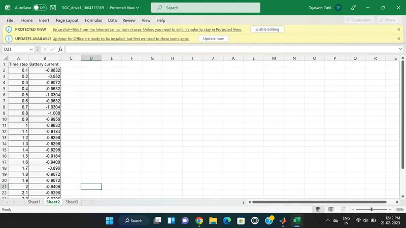
| Time | Time Step | Battery Current |
| 00:00.4 | 0.1 | -0.9632 |
| 00:00.5 | 0.2 | -0.952 |
| 00:00.6 | 0.3 | -0.9072 |
| 00:00.7 | 0.4 | -0.9632 |
| 00:00.8 | 0.5 | -1.0304 |
| 00:00.9 | 0.6 | -0.9632 |
| 00:01.0 | 0.7 | -1.0304 |
| 00:01.1 | 0.8 | -1.008 |
| 00:01.2 | 0.9 | -0.9856 |
| 00:01.3 | 1 | -0.9632 |
| 00:01.4 | 1.1 | -0.9184 |
| 00:01.5 | 1.2 | -0.9296 |
| 00:01.6 | 1.3 | -0.9296 |
| 00:01.7 | 1.4 | -0.9296 |
| 00:01.8 | 1.5 | -0.9184 |
| 00:01.9 | 1.6 | -0.9408 |
| 00:02.0 | 1.7 | -0.896 |
| 00:02.1 | 1.8 | -0.9072 |
| 00:02.2 | 1.9 | -0.9072 |
| 00:02.3 | 2 | -0.9408 |
| 00:02.4 | 2.1 | -0.9296 |
| 00:02.5 | 2.2 | -0.9296 |
| 00:02.6 | 2.3 | -0.9968 |
| 00:02.7 | 2.4 | -0.9968 |
| 00:02.8 | 2.5 | -0.9408 |
| 00:02.9 | 2.6 | -0.9408 |
| Battery resistance | 2 milli ohm |
Consider the battery resistance is 0.5 mOhm, delta time is 0.1 and entropic factor is 2
AIM -To find Maximum Heat generation by the battery and Build the Simulink model for SOC of the battery at 2*104 second of battery operation.
THEORY -
Heat generated = joules heat + entropy heat
joules heat ,from ohms law we know that
V=IR
when the current flowing through a resistance, there is a heat dissipated inn the resistor this heat dissipation is called joules heating. Joules heating is also known as ohmic heating.
power P=V*I=I^2*R
Heat H=∫P.dt with the limits of time 0 to t
H=I^2*R*t
where,
P=power
V=voltage
I=current
R=resistance
H=heat
T=time
Entropy heat - The heat generation due to entropy change inside a battery occurs when electro chemical reaction are performed. the entropy heat is reversible heat resulting from change in open circuit voltage with respect to temperature at two electrodes.
batterry resistance = 0.5m ohm = 0.0005ohm.
Calculation -
Maximum current = -0.896 A
Maximum current time = 2 min = 120 sec
Entropic factor = 2
Total heat generation = Joule heat + Entropy heat
The maximum heat generation in the battery pack is given by
Maximum heat generation = Max Joule Heat + Entropy factor
Maximum Joule Heat = I^2 *R*t
Maximum Joule Heat = (-0.896)^2*0.5*120
= 48.168 mJ
Maximum heat generated = 48.168 mJ +2
=50.168 mJ
The Maximum Heat generation is 50.168 milijoules .
2. The SOC of the battery at 2 *104second of the battery operation.
The state of charge (SOC) is a measurement of the amount of energy available in a battery at a specific point in time expressed as a percentage. The SOC provides the user with information of how much longer the battery can perform before it needs to be charged.
SIMULINK MODEL -
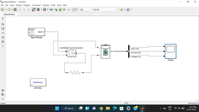
Converts the Simulink input signal into an equivalent current source. The generated current is driven by the input signal of the block. You can initialize your circuit with a specific AC or DC current.
3. Bus Selector -
This block accepts a bus as input which can be created from a Bus Creator, Bus Selector or a block that defines its output using a bus object. The left listbox shows the elements in the input bus. Use the Select button to select the output elements. The right listbox shows the selections. Use the Up, Down, or Remove button to reorder the selections. Check 'Output as virtual bus' to output a single bus.
Scope displays the output graph and powergui block set simulation type, simulation parameters, and preferences.
Explanation:
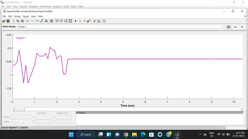
- The above signal is given as a input to the battery block. The Excel sheet is loaded into the Signal Builder block and signal builder block ouput is given to the controlled current source.
- The Simulation stop time is 2*104 seconds ie 208Seconds.
- The Signal builder acts as a load to the battery.
- The Battery Block shows the SOC, Voltage and Current through the bus selector block.
- The output is displayed through Scope block. It shows the nature of SOC%, Current and Voltage .
