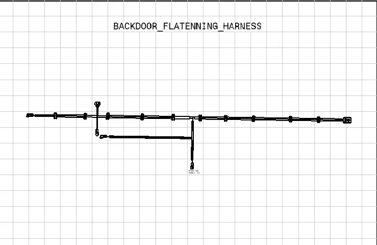
Project 2
Project 2:
- AIM: To Design a Route for the Wiring harness on the Given backdoor and prepare a flattened view drawing in CATIA V5.
- Objective:
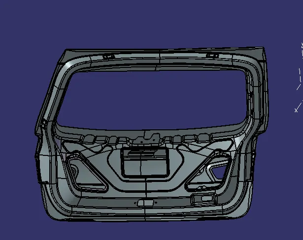
- Here, as input, we got the backdoor Part body and had to route the wiring.
- So first, let analysis the electrical connection required component.
- Here we have 6 connectors and mounting equipment required.
- Creating the context assembly for routing the Backdoor:
- Create the new product file and import the Backdoor CAT file.
2. Defining the electrical components as required:
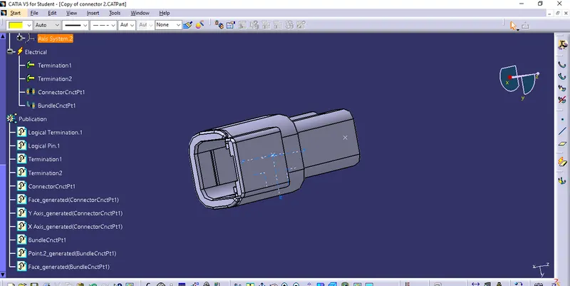
- Connector connection point:
- It is the point at which the plug and connector mating surfaces are connected.
- To create such a connector connection point, follow the below steps:
- Switch to part design,
- Create a midpoint on the contact face which will be normal to wire bundle insertion.
- Create Axis System with respect to the point which we have created and define the axis direction as shown below,
- Switch to 'Electric Part Design'
- Define the part as the connector in CATIA V5, and give the no. of termination as needed.
- Define connector connection point.
- Bundle connection point:
- The bundle connection point is used to specify the position and the direction of the bundle segment connected to the connector or the equipment.
- To create such a Bundle connection point, follow the below steps:
- Switch to part design,
- Create a midpoint on the contact face which will be normal to wire bundle insertion.
- Switch to 'Electric Part Design'
- Since we had already defined the component as a connector.
- so, Define the Bundle connection point.
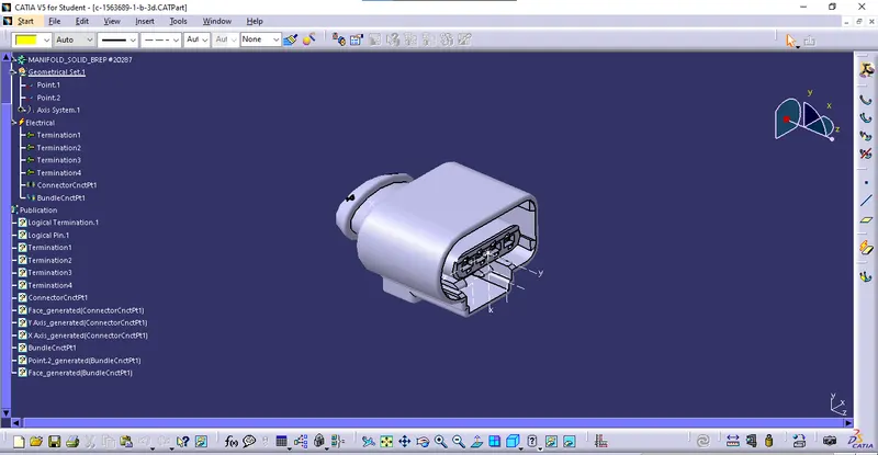
- C-1563689-1:
Defining the four-pole terminal connector electrically.
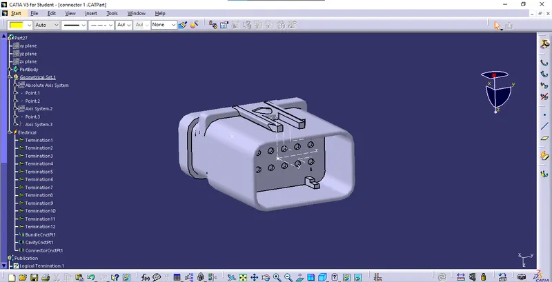
- 12-pole connector:
- 3-pole connector:
- P-clamp:
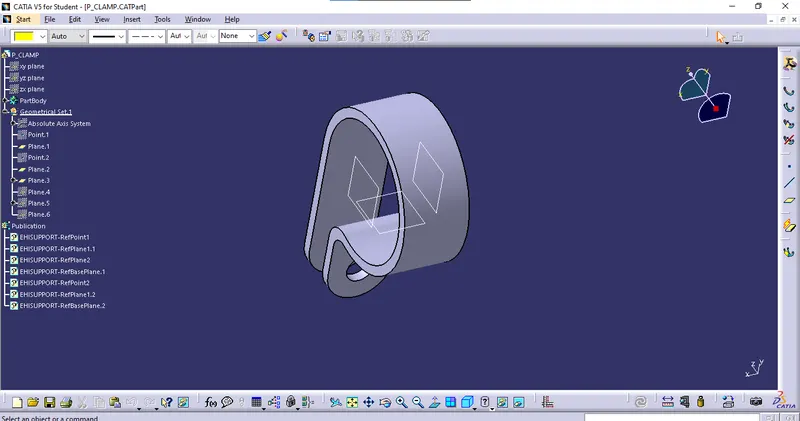
3. Placement of Connector, Clamp, Channel, and Route of the Bundle:
- After Defining the component as electrical, let's place those electric components as per the location provided in the backdoor.
- To place those components we can use,
- Manipulation tool
- Snap Tool
- Smart Move Tool
- Compass
- others Tool
- Now after placing the electric component at the location.
- Let's Start Bundle Routing.
- After Routing the bundle, provide the Cot-Tubes over the Bundle.
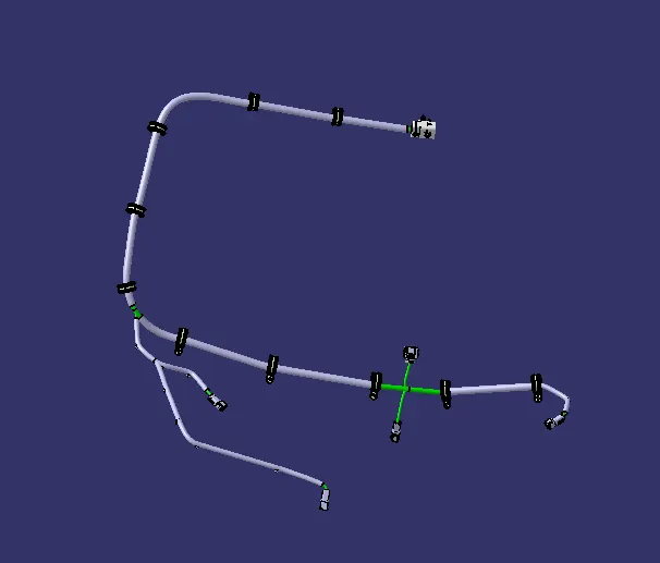
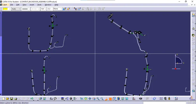
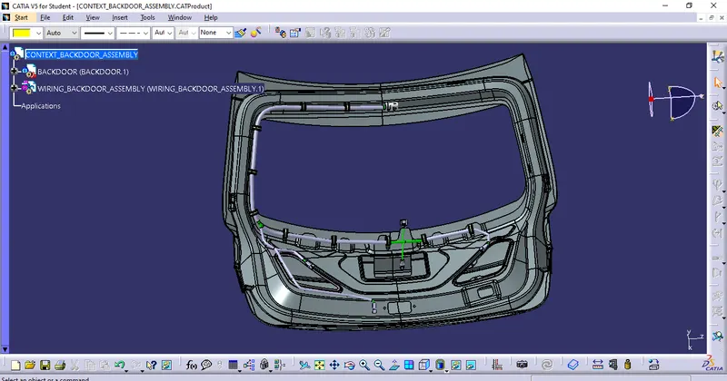
4. Checking the bundle Continuity. Adding the snap of results in the submission:
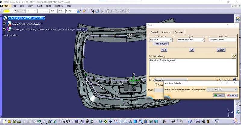
- Go to edit menu
- Select the Search option and in that select the advance option
- set the following option
- electrical
- bundle segment
- fully connected
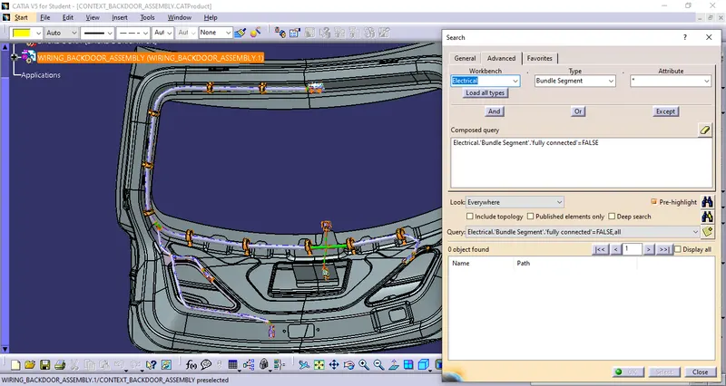
- provide condition (true/false)
- After providing a constraint select the highlight option.
5. Flattening and 2-D drawing:
- After completing Routing and providing the Cot tube to it.
- Let's flatten the bundle.
- STEPS FOR FLATTENING THE ASSEMBLY:
- open the existing assembly which should be flattened.
- After opening the file create the new product file.
- Rename it first and save the file in the exact location where the existing assembly was saved.
- Switch to electrical flattening assembly.
- Set the flattening parameters.
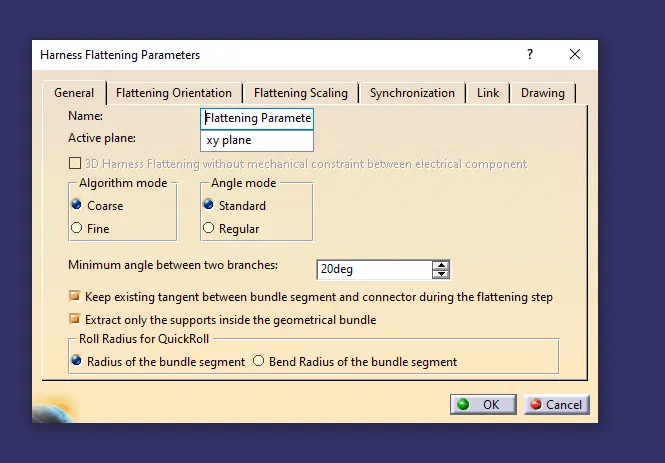
- After setting the parameters, select the extract tool to extract the existing assembly.
- Once it's extracted, go to flatten tools.
- select the plane in which respect we have to flatten the assembly.
- With the Rotate tool's help, arrange the assembly representation.
- Hence the assembly gets flattened.
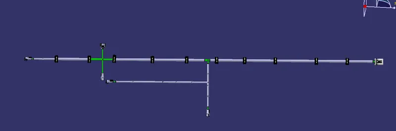
- CREATING 2D DRAWING:
- After flattening the assembly, create a new drawing.
- select the front view tool and select the view from the flattening assembly
- As there might be some mismatched will be there.
- Check the parameters of the flattening workbench,
2. right click on the 2d drawing and enable the 3d wireframe and make it always visible.
- After applying the setting, we got our desired drawing on the sheet.