Project
Aim: Study the modeling of a CVT Baja All-Terrain Vehicle.
Objective:
- Study the Baja ATV model without a dashboard.
- Study the Baja ATV model with a dashboard.
- Study the Baja ATV model with a lookup table without a dashboard.
- Study the Baja ATV model with a lookup table with a dashboard.
Theory:
Continuous Variable Transmission (CVT)
The idea of continuously variable transmission is given by one of the greatest minds of the time i.e. “Leonardo – da – Vinci” in 1490. A continuously variable transmission system is a type of automatic transmission in which an arrangement of pulleys and belts made it possible for a drive to achieve n-number of continuous gear ratios within a range (depends on the design).
A continuously variable transmission in a vehicle senses the accelerator input with engine load and gets shifted to the desired speed or torque gear ratio automatically. In other words, we can say that a CVT transmission is one of the simplest types of automatic transmission that provides continuous uninterrupted power within a specified range of speed and torque ratios.
How CVT Works?
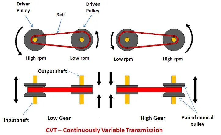
As we all know the basic function of any transmission system whether manual or automatic is to provide variable speed or torque ratios as per the requirement of the drive. When a driver presses the accelerator pedal or accelerator handle (in the case of 2-wheelers) the engine shaft rotates according to the accelerator input which in turn rotates the input shaft. With the input shaft rotation, input pulleys mounted over it also rotates which in turn rotates the belt wrapped around them. This belt transfers power from the input shaft to the output pulley as it is also wrapped around the output pulleys. Output pulleys rotate the output shaft and the final output is obtained.
Torque Ratios
When a vehicle needs high torque ratios the feeding input conical pulley (sheave) over the input shaft moves away from the fixed pulley which in turn shift part of the V-belt wrapped over the input pulleys towards the lower cross-sectional part of the conical pulley. Simultaneously when this input pulley(sheave) moves, the feeding output pulley (sheave) also moves and comes closer to the fixed output pulley which in turn shift the part of the V-belt wrapped over the output pulleys towards the greater cross-sectional area of the output conical pulleys and desired torque ratios is attained.
Speed Ratios
When the vehicle needs speed ratios, the feeding conical pulley (sheave) over the input shaft moves towards the fixed pulley which in turn shifts the part of the V-belt wrapped over the input pulleys towards the greater cross-sectional part of the conical input pulleys. Simultaneously with this movement of input pulley, the feeding output pulley (sheave) also moves and go away from the fixed pulley which in turn moves the part of the V-belt wrapped around the output pulleys towards the lower cross-sectional part of the conical output pulleys and desired speed ratio is attained.
In other words, torque ratios are achieved when the V-belt rotates at the lower cross-section of the input pulleys and at the greater cross-section of the output pulley. And speed ratios are achieved when V-belt rotates at the higher cross-section of the input pulley and the lower cross-section of the output pulley.
All-Terrain Vehicle (ATV)
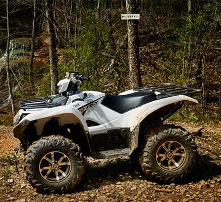
An all-terrain vehicle (ATV) is defined as a motorized off-highway vehicle designed to travel on four low-pressure or non-pneumatic tires, having a seat designed to be straddled by the operator and handlebars for steering control. ATVs are subdivided into two types as designated by the manufacturer. Type I ATVs are intended by the manufacturer for use by a single operator and no passenger. Type II ATVs are intended by the manufacturer for use by an operator and a passenger and are equipped with a designated seating position behind the operator. Similarly, riders must also consider the various ATV sizes.
Study-1: Study the Baja ATV model without a dashboard.
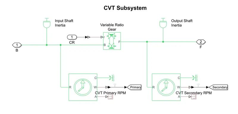
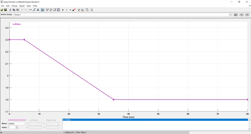
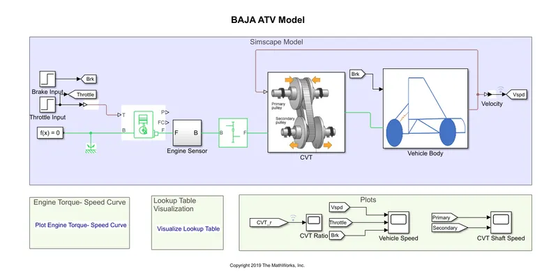
Fig-3 is the representation of the Baja ATV Model for continuous variable transmission. This model consists of two subsystems i.e CVT Subsystem and Vehicle Body Subsystem (see Fig-2 & Fig-3). The signal builder is used to provide the Brake and Throttle input for the vehicle. Another signal builder "cvtRatio" is used to give the CVT Ratio to the CVT Transmission. Two output plot blocks are used to display the signals of Velocity, Throttle, Brake, and Primary & Secondary CVT Shaft Speed.
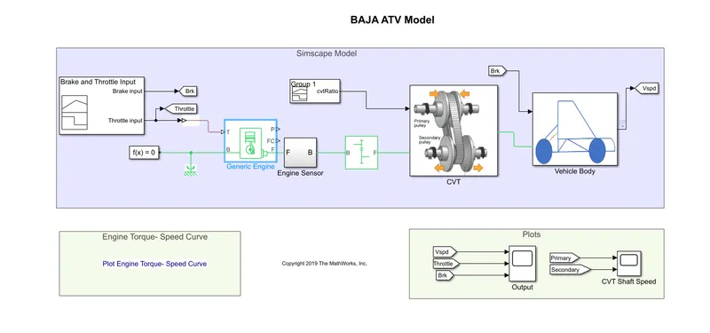
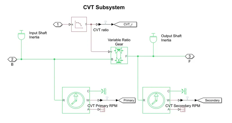
The CVT Subsystem consists- Input Shaft Inertia, Output Shaft Inertia, Variable Gear Ratio, and Ideal Rotational Sensors.
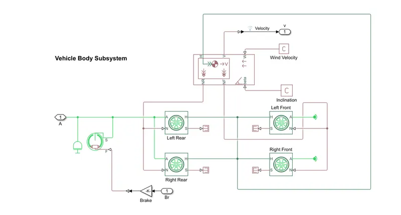
The Vehicle Body Subsystem is a representation of the vehicle body includes all tires and vehicle body information such as
Mass: 250 kg
Number of wheels per axle: 2
Horizontal distance from CG to front axle: 1 m
Horizontal distance from CG to rear axle: 0.35 m
CG height above ground: 0.7 m
Gravitational acceleration: 9.81 m/s^2
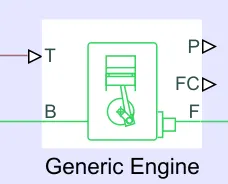
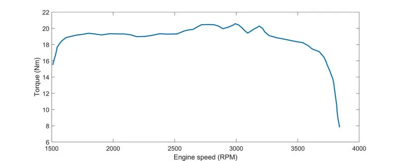
The Generic Engine block represents a general internal combustion engine. This block is a suitable generic engine for spark-ignition and diesel. Speed-power and speed-torque parameterizations are provided by tabular data.
Input:
The initial inputs in the model are given for the:
Engine Inertia= 1 kg*m^2
Initial Velocity= 2100 RPM
Gear Ratio=4
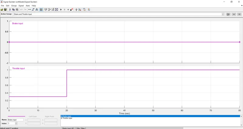
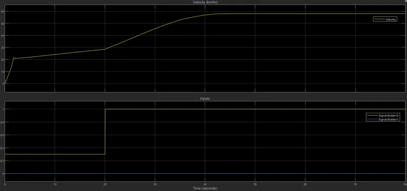
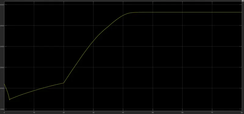
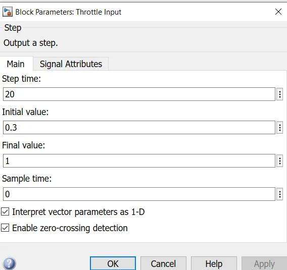
The signal builder is used as inputs for the brake and throttle for the engine. The brake input is 0 for the overall simulation and the throttle is 0.3 for 0-20 seconds and after that throttle was 1 up to 80 seconds.
The CVT gear ratio is maintained at 2.3 for the first 5 seconds and after that linearly decreases to 1.8 for the next 30 seconds. After 35 seconds, the gear ratio became constant at 1.4 for the next 45 seconds.
The engine speed and Torque relation is given in this figure. This data is given in the generic engine.
Output:
The figure below gives the output of the simulation in terms of velocity. As we can see that the brake input is zero and the throttle was 0.3 for the first 20 seconds and after that throttle is 1. The graph of the velocity is increased from 0 to 80 seconds which explains that as we will increase the throttle value the vehicle velocity will also increase.
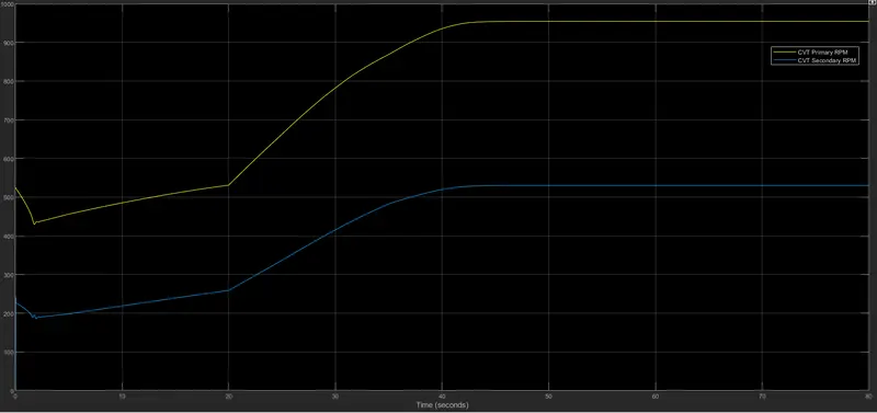
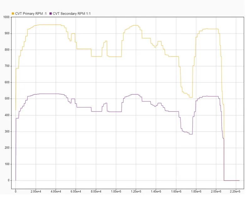
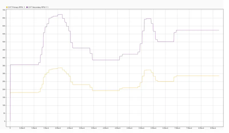
As we can see that the speed of the primary shaft is higher than the secondary shaft because the radius of the primary shaft is more than the secondary shaft. So it can be said that the speed of the shaft is proportional to the shaft radius. If the radius increases the speed increases and vice-versa.
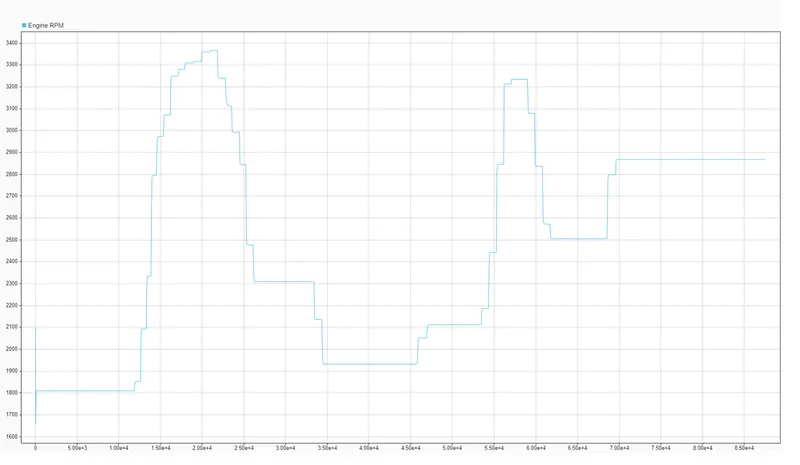
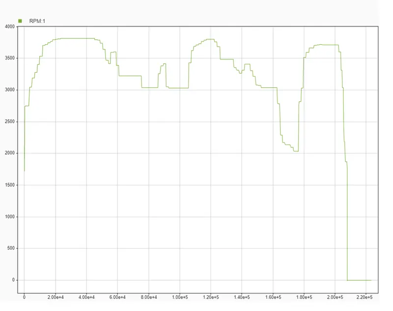
The figure below shows the engine RPM of the Baja ATV model used in the simulation.
Study-2: Study the Baja ATV model with a dashboard.
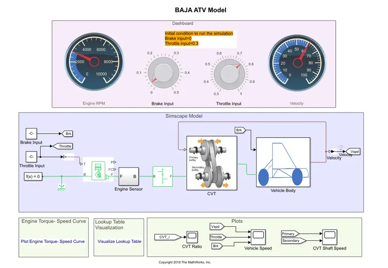
The Simulink model of the Baja ATV model with a dashboard is given below. All the parts and subsystems are the same as the model used in study-1. The only difference is here is that we used a "Dashboard". Knobs are used for throttle and brake inputs to the vehicle body and Gauges are used to see the engine RPM and Velocity of the vehicle.
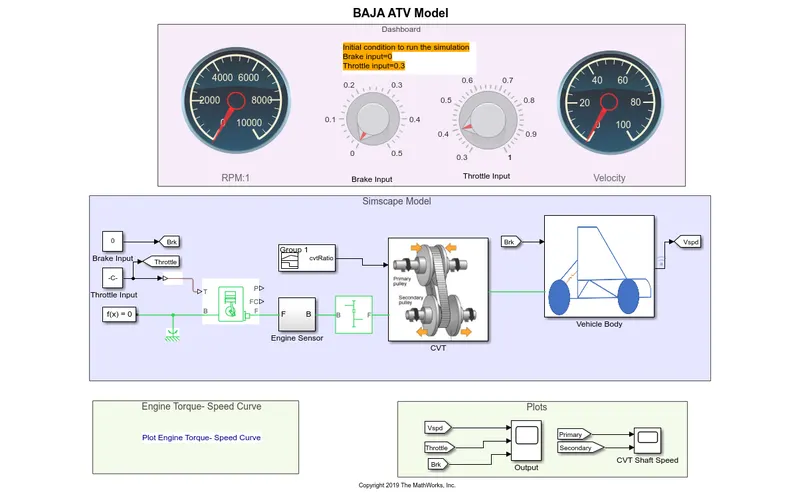
Input:
The initial inputs in the model are given for the:
Engine Inertia= 1 kg*m^2
Initial Velocity= 2100 RPM
Gear Ratio=4
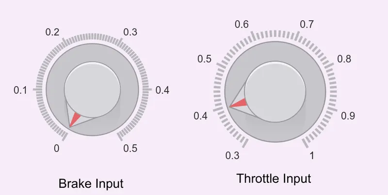
The brake input range is from 0 to 0.5 and the throttle input is from 0.3 to 1. The CVT ratio of the vehicle is the same as Study-1.
Output:
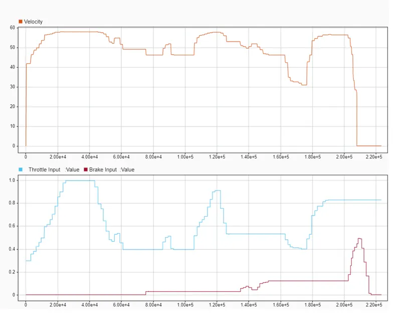
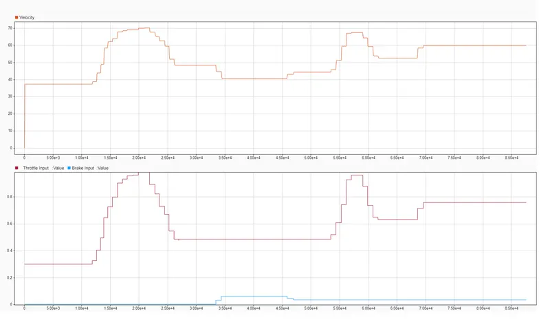
From the figure, it can understand that as we increased the throttle, the velocity is increased. The velocity reduces when applying the brake.
The figure below shows the relation between the primary shaft and the secondary shaft of the CVT.
The figure below shows the engine RPM in the simulation.
Study-3: Study the Baja ATV model with a lookup table without a dashboard.
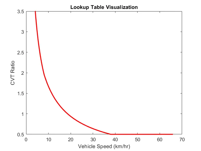
A Simulink model of the Baja ATV Model using Lookup table is given below. This model does not contain a dashboard. As we know the CVT Ratio depends on the vehicle velocity, therefore, this closed-loop model is used which has an in-built lookup table. In Study-1 and Study-2, the CVT ratio is provided by the random values, which cannot be considered as real simulation. To make the simulation real and more accurate we are using this closed-loop model.
The CVT Subsystem consists- Input Shaft Inertia, Output Shaft Inertia, Variable Gear Ratio, and Ideal Rotational Sensors. The CVT ratio is provided in the "Variable Ratio Gear" block and rest all the parameters are the same as previous.
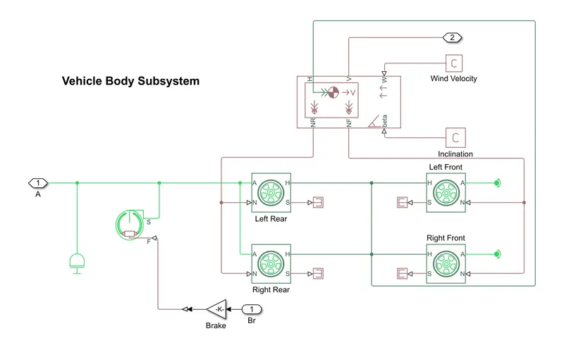
The Vehicle Body Subsystem is a representation of the vehicle body includes all tires and vehicle body information.
Input:
The initial inputs in the model are given for the:
Engine Inertia= 1 kg*m^2
Initial Velocity= 2100 RPM
Gear Ratio=12
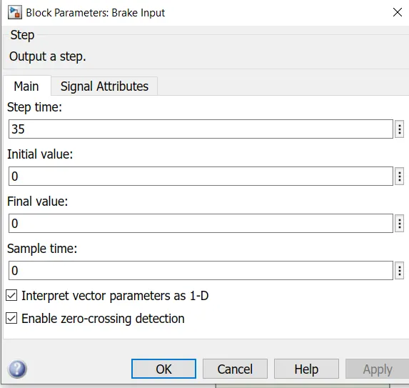
Step signal block is used for Brake and Throttle input.
Lookup Table:
Output:
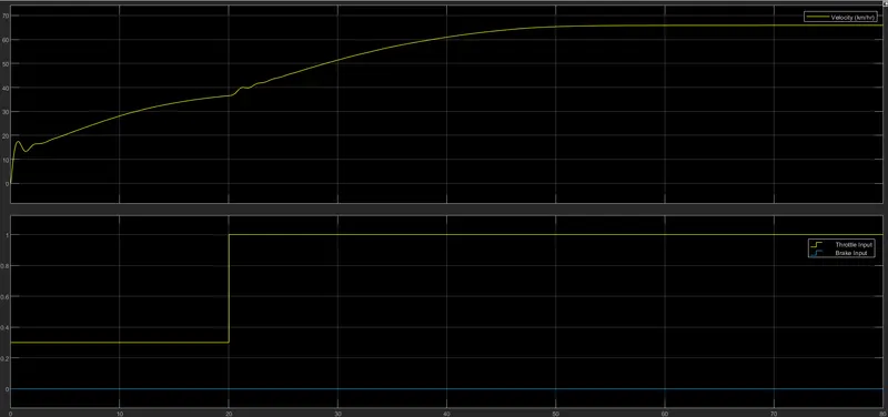
The figure shows the variation in velocity as changing the brake and throttle inputs.
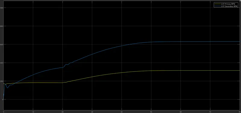
This figure shows the relation between the Primary shaft RPM and the Secondary shaft RPM in CVT.
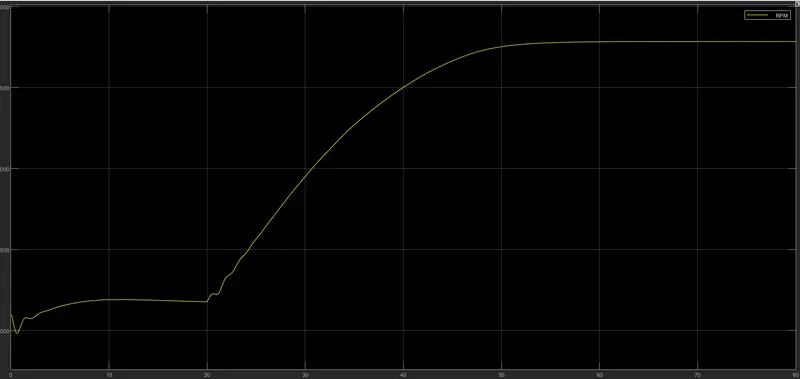
The variation in engine RPM in simulation is given below.
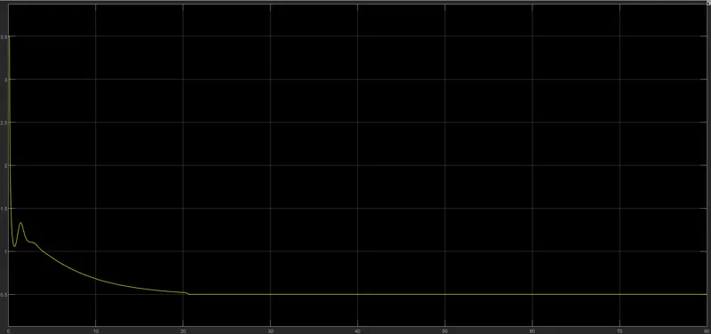
The variation in the CVT Ratio is given in the figure below.
Study-4: Study the Baja ATV model with a lookup table with a dashboard.
The Simulink model of the Baja ATV model with a lookup table and dashboard is given below. All the parts and subsystems are the same as the model used in Study-3. The only difference is here is that we used a "Dashboard". Knobs are used for throttle and brake inputs to the vehicle body and Gauges are used to see the engine RPM and Velocity of the vehicle.
Input:
The initial inputs in the model are given for the:
Engine Inertia= 1 kg*m^2
Initial Velocity= 2100 RPM
Gear Ratio=12
The Knobs are used for providing Brake and Throttle inputs.
Output:
From the figure, it can understand that as we increased the throttle, the velocity is increased. The velocity reduces when applying the brake.
The figure below shows the relation between the primary shaft and the secondary shaft of the CVT.
The figure below shows the variation in engine RPM in the simulation.