Project
AIM:- To simulate the specified all-terrain vehicle at the system level and to create a technical report outlining the model's attributes and offering comments on the outcomes.
THEORY:
BAJA :
Baja SAE is an Collegiate Design Series competition run by the Society of Automotive Engineers International (SAE International). Teams of students from universities all over the world design and build small off-road cars. The cars all have engines of the same specifications. As of 2018 the engine has been an unmodified Briggs & Stratton Model 19 Vanguard engine single-cylinder with a displacement of 305cc and power output of approximately 10 bhp (7.5 kW).
The goal in Baja SAE racing is to design, build and race off-road vehicles that can withstand the harshest elements of rough terrain. The vehicles used in Baja SAE racing are often similar in appearance to dune buggies.
ATV:
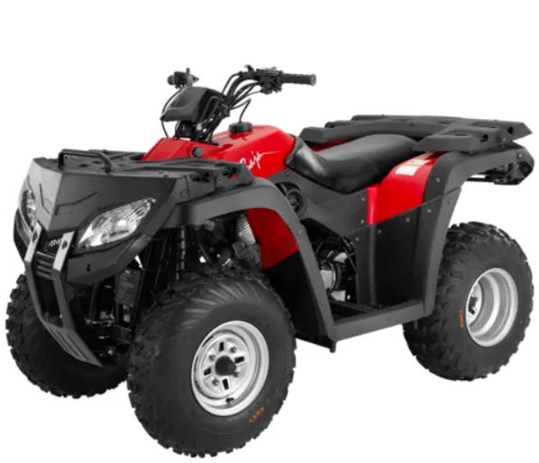
- An all-terrain vehicle (ATV) refers to a motorized single-seated tri or quadricycle bike and buggy that is designed for off-road travel and activities. The vehicle consists of handlebars and low-pressure tires that have deep-threaded structures, which assist in driving over muddy, rocky, wetlands and dune topologies. In comparison to other utility vehicles (UTVs), ATVs offer excellent off-road capabilities and can carry heavy equipment over long distances and narrow access points. They can also be customized for high-performance riding, owing to which they find extensive applications across various industries, including sports, entertainment, agriculture, military and defense.
CVT:
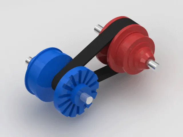
- A CVT or Continuously Variable Transmission is an automatic, single-speed, and gearless transmission that can shift through an infinite number of gear ratios.
- A continuously variable transmission (CVT) is a transmission that operates on an ingenious pulley system that automatically varies the transmission ratio, allowing an infinite variability between highest and lowest gears with no discrete steps or shifts. CVTs provide more usable power, better fuel economy and smoother driving experience than traditional transmissions that use gearboxes with fixed numbers of gear sets.
- CVTs differ from traditional automatic transmissions in that they don't have gears that provide "steps" between low- and high-speed operation. Instead, the majority of them work via a pair of variable-diameter, cone-shaped pulleys connected by a steel or composite belt.
SIMULINK MODEL
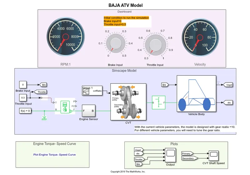
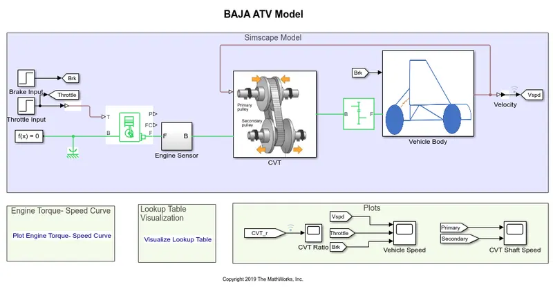
This is a simulink model of cvtModel_dashboard for All Terrain Vehicle (ATV).
- In this model we have a two input signals. Those are Brake Input and Throttle Input.
- You can see input value of Brake and throttle as a nobe in dashboard and also you can see RPM meter and velocity indicates meter.
- In the simscape model you can see whole Baja ATV Drivetrain.
- Here, Input value of brake and throttle are just like driver foot pedal input.This input is give to the Generic Engine and output power of Generic Engine is supply for Engine Sensor and CVT Subsystem. Output power pass through the Simple Gear to the Vehicle Body and finally we got the answer.
- The simulation output is get from last simulink area box. There are two scope, one is give information about velocity(or vehicle speed), distance, throttle and brake output. Second is give information about CVT Shaft Speed.
Generic Engine :-
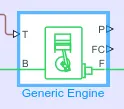
- Internal combustion engine with throttle and rotational inertia and time lag
- The Generic Engine block represents a general internal combustion engine. This block is a suitable generic engine for spark-ignition and diesel. Speed-power and speed-torque parameterizations are provided. A throttle physical signal input specifies the normalized engine torque. Optional dynamic parameters include crankshaft inertia and response time lag. A physical signal port outputs the engine fuel consumption rate based on the fuel consumption model that you choose. Optional speed and redline controllers prevent engine stall and enable cruise control.
- Represents a system-level model of spark-ignition and diesel engines suitable for use at initial stages of modeling when only the basic parameters are available. Optional idle speed and red line controllers are included.
- The throttle input signal T lies between zero and one and specifies the torque demanded from the engine as a fraction of the maximum possible torque. If the engine speed falls below the Stall speed, the engine torque is blended to zero. If the engine speed exceeds the Maximum speed, the simulation stops and issues an error message.
- Connections F and B are mechanical rotational conserving ports associated with the engine crankshaft and engine block, respectively. Connections P and FC are physical signal output ports through which engine power and fuel consumption rate are reported.
- To improve simulation performance, set the Dynamics > Time Constant parameter to No time constant - Suitable for HIL simulation.
Simple Gear
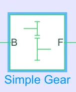
- Simple gear of base and follower wheels with adjustable gear ratio, friction losses, and triggered faults.
- The Simple Gear block represents a gearbox that constrains the connected driveline axes of the base gear, B, and the follower gear, F, to corotate with a fixed ratio that you specify. You choose whether the follower axis rotates in the same or opposite direction as the base axis. If they rotate in the same direction, the angular velocity of the follower, ωF, and the angular velocity of the base, ωB, have the same sign. If they rotate in opposite directions, ωF and ωB have opposite signs.
- Represents a fixed-ratio gear or gear box. No inertia or compliance is modeled in this block. You can optionally include gear meshing and viscous bearing losses.
- Connections B (base) and F (follower) are mechanical rotational conserving ports. Specify the relation between base and follower rotation directions with the Output shaft rotates parameter. Optionally include thermal effects and expose thermal conserving port H by setting Friction model to a temperature-dependent setting.
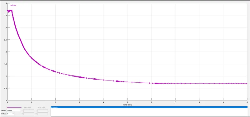
CVT Ratio :- Signal builder input.
Engine Sensor subsystem:-
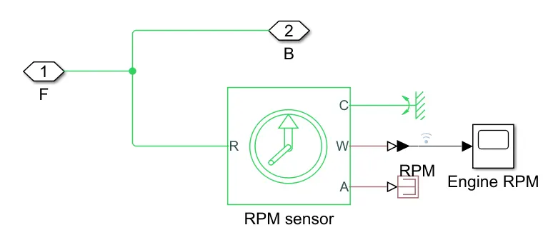
RPM Sensor :- (Ideal Rotational Motion Sensor)
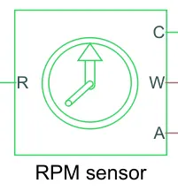
- The Ideal Rotational Motion Sensor block represents an ideal mechanical rotational motion sensor, that is, a device that converts an across variable measured between two mechanical rotational nodes into a control signal proportional to angular velocity or angle. You can specify the initial angular position (offset) as a block parameter.
- The sensor is ideal since it does not account for inertia, friction, delays, energy consumption, and so on.
- Connections R and C are mechanical rotational conserving ports that connect the block to the nodes whose motion is being monitored. Connections W and A are physical signal output ports for velocity and angular displacement, respectively.
- This block measures angular velocity or angle in a mechanical rotational network. The sensor is ideal since it does not account for inertia, friction, delays, energy consumption, and so on.
- The physical signal ports W and A report the angular velocity and angle, respectively, of port R relative to port C. The measured angular velocity is positive when the angular velocity at port R is greater than the angular velocity at port C.
CVT Subsystem :-
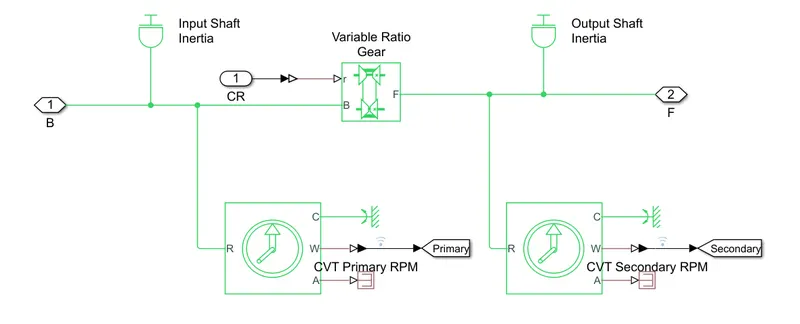
Inertia block :-

- The block represents an ideal mechanical rotational inertia.
- The block has one or two mechanical rotational conserving ports. The difference is purely graphical, as the ports are rigidly linked. The block positive direction is from its port to the reference point. This means that the inertia torque is positive if the inertia is accelerated in the positive direction.
- The Inertia block represents an ideal mechanical translational inertia that is described with the following equation:
T=J*(dω/dt)
where:
-
T is inertia torque.
-
J is inertia.
-
ω is angular velocity.
-
t is time.
-
Variable Ratio Transmission :-
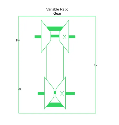
- Dynamic gearbox with variable and controllable gear ratio, transmission compliance, and friction losses.
- The Variable Ratio Transmission block represents a gearbox that dynamically transfers motion and torque between the two connected driveshaft axes, base and follower.
- Ignoring the dynamics of transmission compliance, the driveshafts are constrained to corotate with a variable gear ratio that you control. You can choose whether the follower axis rotates in the same or opposite direction as the base axis. If they rotate in the same direction, ωF and ωB have the same sign.If they rotate in opposite directions, ωF and ωB have opposite signs.
- Transmission compliance introduces internal time delay between the axis motions. Therefore, unlike a gear, a variable ratio transmission does not act as a kinematic constraint. You can also control torque loss caused by transmission and viscous losses.
- Ports :-
- B and F are rotational conserving ports representing, respectively, the base and follower driveshafts.
- You specify the unitless variable gear ratio gFB(t) as a function of time at the physical signal input at port r. If the signal value becomes zero or negative, the simulation stops with an error.
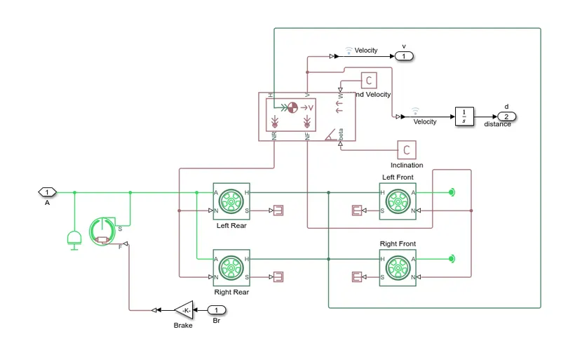
Vehicle Body Subsystem
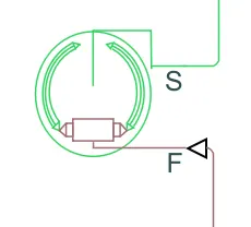
Double-Shoe Brake :-
- Frictional brake with two pivoted shoes diametrically positioned about a rotating drum with triggered faulting.
- Represents a brake arranged as two pivoted rigid shoes symmetrically installed inside or outside a drum and operated by one actuator. The actuator force causes the shoes to exert a friction torque on a shaft connected to the drum.
- Connection S is a conserving rotational terminal associated with the drum shaft. Connection F is a physical signal port representing the force input to the actuator. Positive force creates friction torque that resists shaft rotation. Optionally include thermal effects and expose thermal conserving port H by setting Thermal port to Model.
- The Double-Shoe Brake block represents a frictional brake with two pivoted rigid shoes that press against a rotating drum to produce a braking action. The rigid shoes sit inside or outside the rotating drum in a diametrically opposed configuration. A positive actuating force causes the rigid shoes to press against the rotating drum. Viscous and contact friction between the drum and the rigid shoe surfaces cause the rotating drum to decelerate.
- Double-shoe brakes provide high braking torque with small actuator deflections in applications that include motor vehicles and some heavy machinery. The model employs a simple parameterization with readily accessible brake geometry and friction parameters.
- You can also enable faulting. When faulting occurs, the belt will exert a user-specified force. Faults can occur at a specified time or due to an external trigger at port T.
Vehicle Body :-
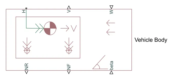
- Two-axle vehicle with longitudinal dynamics and motion and adjustable mass, geometry, and drag properties.
- Represents a two-axle vehicle body in longitudinal motion. The block accounts for body mass, aerodynamic drag, road incline, and weight distribution between axles due to acceleration and road profile. The vehicle can have the same or a different number of wheels on each axle. Optionally include pitch and suspension dynamics or additional variable mass and inertia. The vehicle does not move vertically relative to the ground.
- Connection H is the mechanical translational conserving port associated with the horizontal motion of the vehicle body. The resulting traction motion developed by tires should be connected to this port. Connections V, NF, and NR are physical signal output ports for vehicle velocity and front and rear normal wheel forces, respectively. Wheel forces are considered positive if acting downwards. Connections W and beta are physical signal input ports corresponding to headwind speed and road inclination angle, respectively. If variable mass is modeled, the physical signal input ports CG and M are exposed. CG accepts a two- element vector representing the x and y distance offsets from vehicle CG to additional load mass CG. M represents the additional mass. If both variable mass and pitch dynamics are included, the physical signal port J accepts the inertia of the additional mass about its own CG.
- The Vehicle Body block represents a two-axle vehicle body in longitudinal motion. The vehicle can have the same or a different number of wheels on each axle. For example, two wheels on the front axle and one wheel on the rear axle. The vehicle wheels are assumed identical in size. The vehicle can also have a center of gravity (CG) that is at or below the plane of travel.
- The block accounts for body mass, aerodynamic drag, road incline, and weight distribution between axles due to acceleration and road profile. Optionally include pitch and suspension dynamics. The vehicle does not move vertically relative to the ground.
- The block has an option to include an externally-defined mass and an externally-defined inertia. The mass, inertia, and center of gravity of the vehicle body can vary over the course of simulation in response to system changes.
Tire(magic formula) :-
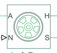
- Tire with longitudinal behavior given by Magic Formula coefficients
- Represents the longitudinal behavior of a highway tire characterized by the tire Magic Formula. The block is built from Tire-Road Interaction (Magic Formula) and Simscape Foundation Library Wheel and Axle blocks. Optionally, the effects of tire inertia, stiffness, and damping can be included.
- Connection A is the mechanical rotational conserving port for the wheel axle. Connection H is the mechanical translational conserving port for the wheel hub through which the thrust developed by the tire is applied to the vehicle. Connection N is a physical signal input port that applies the normal force acting on the tire. The force is considered positive if it acts downwards. Connection S is a physical signal output port that reports the tire slip. Optionally expose physical signal port M by setting Parameterize by to Physical signal Magic Formula coefficients. Physical signal port M accepts a four element vector corresponding to the B, C, D, and E Magic Formula coefficients.
- The Tire (Magic Formula) block models a tire with longitudinal behavior given by the Magic Formula [1], an empirical equation based on four fitting coefficients. The block can model tire dynamics under constant or variable pavement conditions.
- The longitudinal direction of the tire is the same as its direction of motion as it rolls on pavement. This block is a structural component based on the Tire-Road Interaction (Magic Formula) block.
- To increase the fidelity of the tire model, you can specify properties such as tire compliance, inertia, and rolling resistance. However, these properties increase the complexity of the tire model and can slow down simulation. Consider ignoring tire compliance and inertia if simulating the model in real time or if preparing the model for hardware-in-the-loop (HIL) simulation.
Lookup Table:
- A lookup table is an array of data that maps input values to output values, thereby approximating a mathematical function. Given a set of input values, a lookup operation retrieves the corresponding output values from the table. If the lookup table does not explicitly define the input values, Simulink can estimate an output value using interpolation, extrapolation, or rounding, where:
- Interpolation is a process for estimating values that lie between known data points.
- Extrapolation is a process for estimating values that lie beyond the range of known data points.
- Rounding is a process for approximating a value by altering its digits according to a known rule.
- A lookup table block uses an array of data to map input values to output values, approximating a mathematical function. Given input values, Simulink performs a “lookup” operation to retrieve the corresponding output values from the table. If the lookup table does not define the input values, the block estimates the output values based on nearby table values.
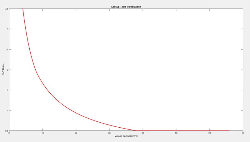
- In place of CVT ratio input, a lookup table is assigned in the models below. It needs to be loaded in the workspace having the file name as Lookuptable_data.mat
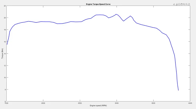
Torque vs Speed characteristics:
SIMULATION
BAJA CVT Without using Lookup Table using dashboard:
- Case 1 :- This is a default case in which brake and throttle input is applied by default.
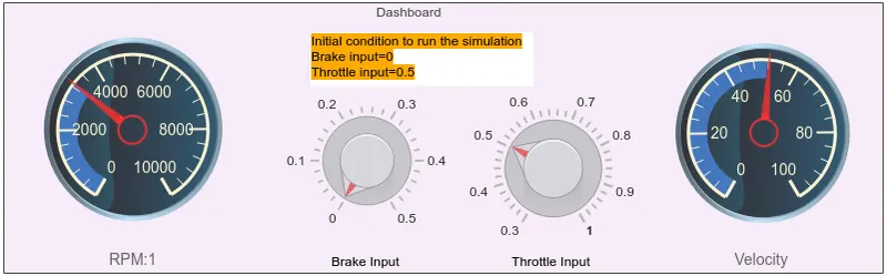
- Here, Throttle input is 0.5 and Brake input is zero it means no braking condition is applied and the simulation run time is 30 second.
- The simulation output is get from last simulink area box. There are two scope, one is give information about velocity(or vehicle speed), distance, throttle and brake output. Second is give information about CVT Shaft Speed.
-
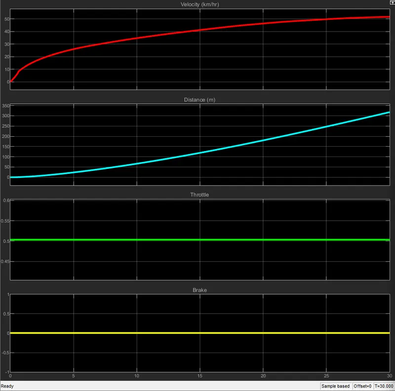
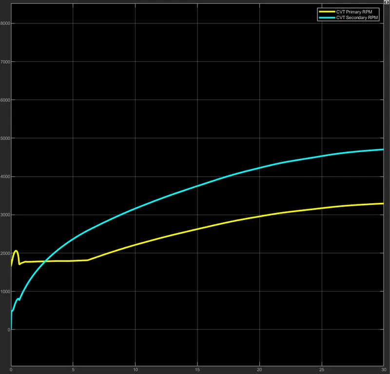
- Here, Vehicle move more than 300m in 30sec. with max velocity of vehicle is nearly 52km/hr. RPM and Velocity is gradually increase with respect to time.
- Case 2 :-
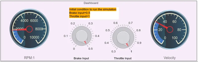
- In this case, Throttle input is maximum and Brake input is also maximum it means full braking and acceleration condition is applied and the simulation run time is 30 second.
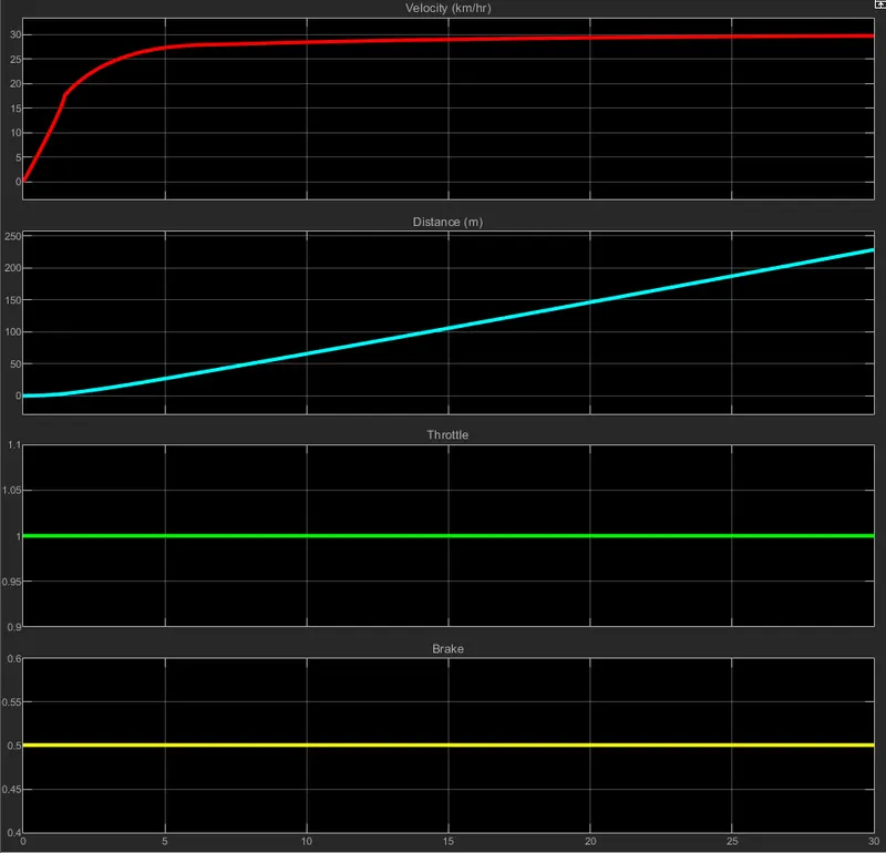
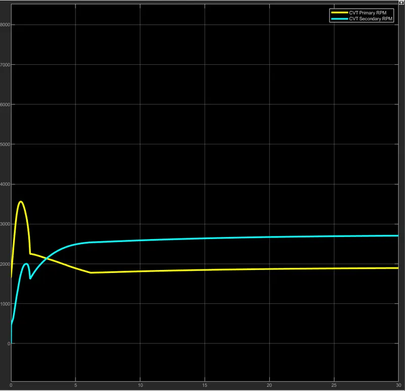
- Here, Vehicle move nearly 225m in 30sec. with max velocity of vehicle is nearly 30km/hr. Velocity is gradually increase at starting point and than it make constant (at 30km/hr) with respect to time.
- Case 3 :-
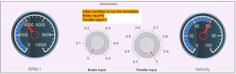
- In this case, Throttle input is maximum and Brake input is zero it means no braking condition is applied and full acceleration condition is applied and the simulation run time is 10 second.
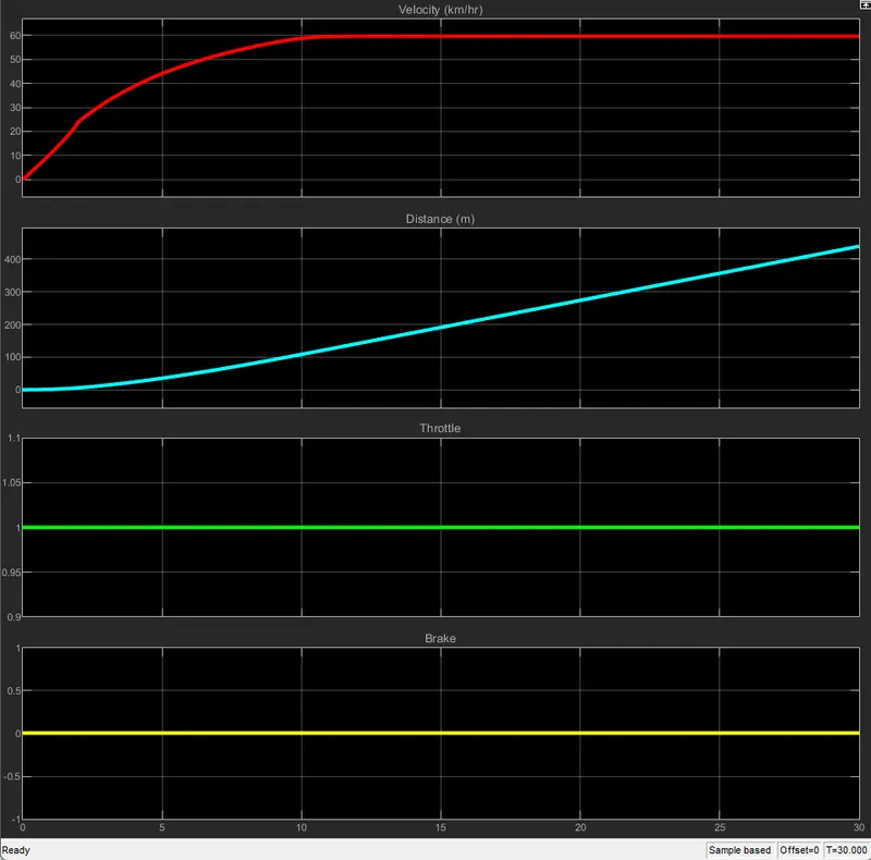
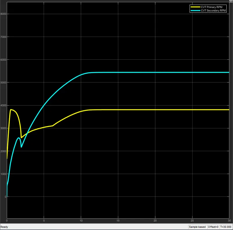
- Here, Vehicle move more than 100m in 10sec. with max velocity of vehicle is closer to 60km/hr. RPM and Velocity is gradually increase with respect to time.
BAJA CVT using Lookup Table:
In this model In place of CVT ratio input, a lookup table is assigned in the models below. It needs to be loaded in the workspace having the file name as Lookuptable_data.mat.
Lookup table
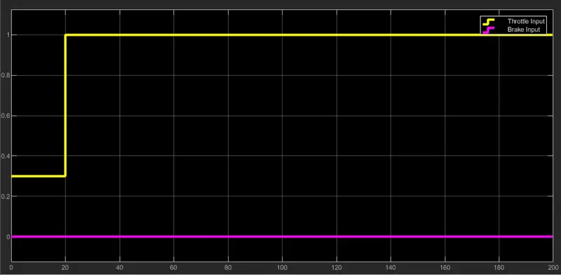
Input :
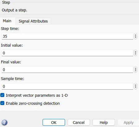
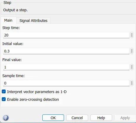
They are given in steps using the step block. Parameters are:
|
Brake Input:
|
Throttle Input:
|
OUTPUT:
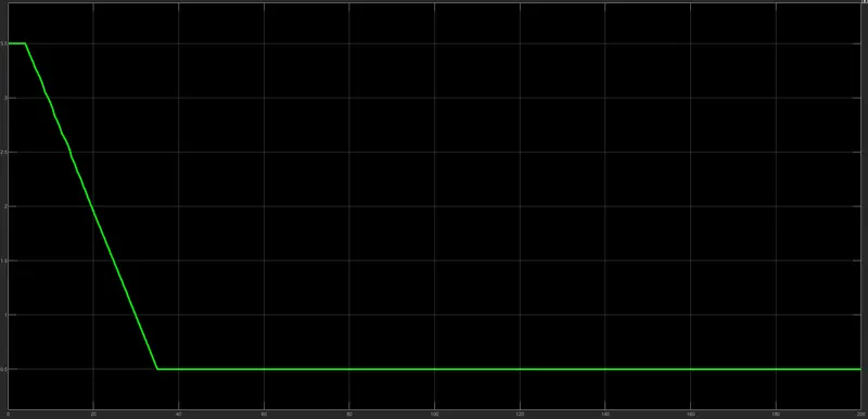
CVT Ratio:
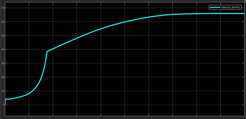
Velocity:
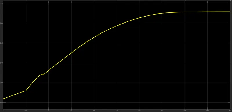
Engine RPM
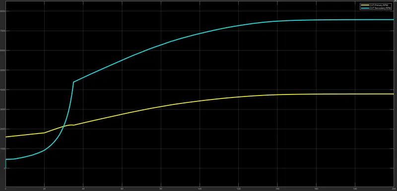
CVT Shaft speed(Primary and Secondary):
CONCLUSION:
Therefore, two key studies were used to model the BAJA ATV with CVT. With a solely CVT-focused approach, this study can demonstrate how CVTs affect vehicle velocity in a variety of scenarios for various ATV design models. From the aforementioned findings, we can deduce the following:
- Throttle input and Brake input have inverse relationships with velocity, CVT shaft speed, and engine speed, respectively.
- The CVT Ratio is inversely proportional to the throttle input and directly proportional to torque.
- Due to the fact that they are inversely correlated with shaft diameter, CVT Primary speed is greater than CVT Secondary speed.
- At a certain braking resistance, the speed may become zero.
REFERENCES:
https://www.mathworks.com/matlabcentral/fileexchange/70576-baja-all-terrain-vehicle-atv-model