Project
AIM
To Study analyse and prepare a technical report for ATV model using the simulink
SOFTWARE
- MATLAB Simulink R2020a
OBJECTIVE
Carry out the simulation of BAJA ATV model and prepare the technical report explaining the simulation with and without using the look up table
THEORY
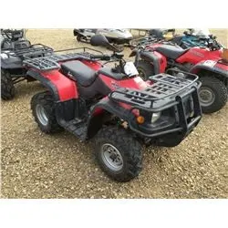
BAJA ATV is an all terrain vehicle. Which is three or four wheeler suitable for many kinds of terrains as its name indicates. ATV has excellent capability of running off the road in any terrain .
power train of an ATV contains an Engine for producing the torque, CVT( Continuously Variable Transmission) to vary the gear ratio, gear assemble to reduce the engine speed and wheel to convert the rotational motion of the shaft to the linear motion and move the vehicle.
SIMULATION COMPONENTS
Generic engine
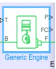
- a system-level model of spark-ignition and diesel engines suitable for use at initial stages of modeling when only the basic parameters are available. Optional idle speed and red line controllers are included.
- Generic engine has five ports
- T is throttle input signal.
- B and F are mechanical rotational conserving points with engine crank shaft and engine block
- P and FC are physical signal outputs with engine power and fuel consumption
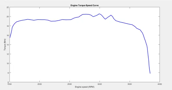
- Speed torque characteristics of the engine are as below
Ideal rotational motion sensor
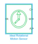
- an ideal mechanical rotational motion sensor, that is, a device that converts an across variable measured between two mechanical rotational nodes into a control signal proportional to angular velocity or angle.
- Rotational motion sensor has 4 ports
- R and C are rotational ports
- W and A are physical signal output of velocity and angular displacement
- Rotational motion sensor is used for measuring the RPM of engine and inputs and outputs of the CVT
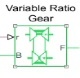
Variable ratio transmission
- Represents a variable ratio gearbox such as implemented by mechanical belt CVT, electric, or hydraulic transmissions.
- Variable ratio transmission has three ports
- r is physical input of gear ratio
- B(Base) and F (follower) are rotational conserving ports.
Simple Gear
- It represents the fixed gear ratio gear box
- It has two ports B (Base) and F(Follower) are rotational conserving points

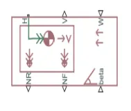
Vehicle body
- Represents a two-axle vehicle body in longitudinal motion. The block accounts for body mass, aerodynamic drag, road incline, and weight distribution between axles due to acceleration and road profile. The vehicle can have the same or a different number of wheels on each axle.
- Vehicle body has six ports
- V,NR and NF are physical signal outputs for vehicle velocity, front and rear normal wheel forces
- W and Beta are physical signal inputs of head wind speed and inclination of road input
- H is mechanical translational port associated with horizontal motion of vehicle
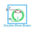
Double shoe break
- Represents a brake arranged as two pivoted rigid shoes symmetrically installed inside or outside a drum and operated by one actuator. The actuator force causes the shoes to exert a friction torque on a shaft connected to the drum.
- it has two ports S is rotational terminal and F is the physical signal associated to force input.
SIMULATION
1) Simulation of model with out look up table
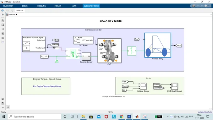
Fig 1.1 BAJA ATV with CVT without look
Fig 1.1 is the model of BAJA ATV with continuously variable transmission without the look up table. In the model we have generic engine with inputs throttle and rotational reference. Output of engine is measured in RPM with rotational motion sensor and Output connected to CVT.
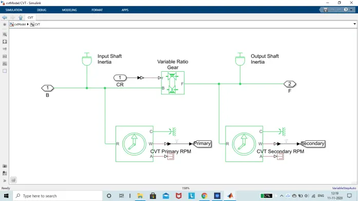
Fig 1.2 Inside CVT subsystem
Fig 1.2 Inside CVT Input shaft is connected to inertia and rotational motion sensor to measure the speed of input shaft. Shaft is connected to variable ratio gear. Output of the variable gear ratio is also connected to output inertia and rotational motion sensor for measuring the output shaft speed. Output of CVT is connected to simple gear as shown in Fig 1.1 for reduction of the shaft speed. Out put of the simple gear is connected to rear wheels with double shoe brake.
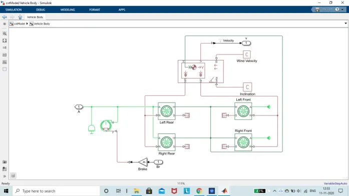
Fig 1.3 Vehicle body and tires
In the Fig 1..3 vehicle body component is connected to tires. Tires are connected to the shaft from simple gear.
To plot values of the throttle , brake input, engine speed, CVT input speed and CVT output speed two scopes are connected as shown in the fig 1.1.
For giving the throttle input , brakes signal and gear ratio for CVT two signal builders are used.
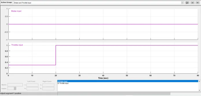
Fig 1.4 brake input and throttle input
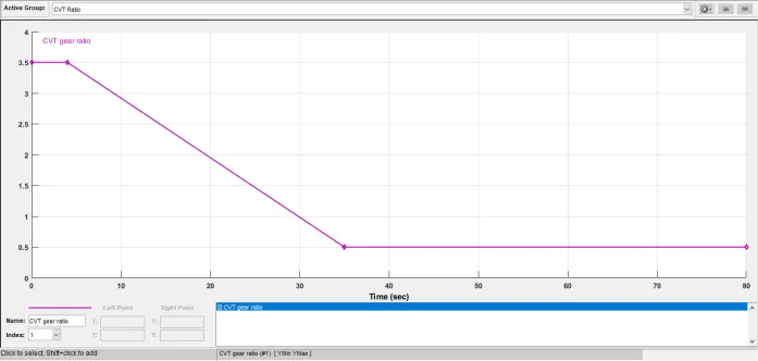
Fig 1.6 scope output with engine velocity, throttle and brake input
From the fig 1.6 we can observe that when the throttle is changed from 0.3 to 1 the engine acceleration has been increased until it reached the saturation.
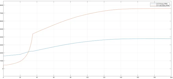
Fig 1.7 scope output of CVT primary and secondary RPM
the output of Engine is connected to the CVT so the primary RPM and Engine speed are almost equal. And the out put of the CVT is based on the gear ratio. It will not based on the output.
In the above simulation throttle fixed. Lets see how the output changes if we change the input throttle and brake with dashboard.
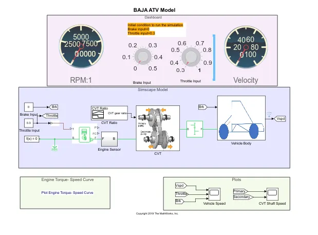
Fig 1.8 BAJA ATV model with Dash board
In this model instead of the giving the standard Input values we can change the throttle and brake values using the dashboard and can observe the how speed and RPM are changing in the Dashboard. The outputs are as below.
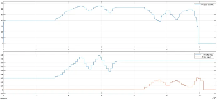
Fig 1.9 scope output of engine and inputs brake and throttle
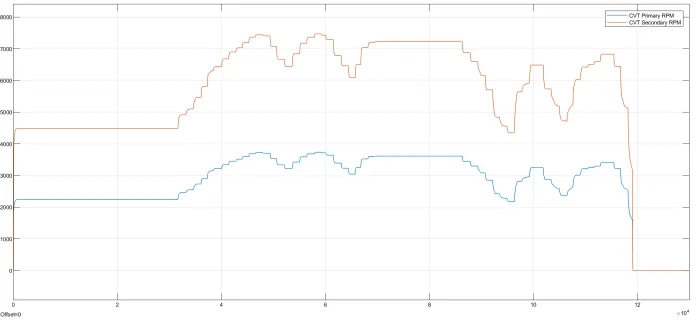
Fig 1.10 scope output of CVT primary and secondary RPM
From the above fig we can observe that speed of secondary shaft is based on primary shaft and input gear ratio we gave but not on vehicle speed.
2) Simulation of the model with look-up table
Look up table is used to change the CVT ratio based on the vehicle speed. It is given with values of CVT ratios for different speeds.
Here is the visualization of look up table
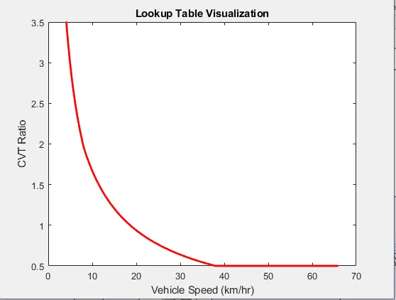
Fig 2.1 visualization of look up table
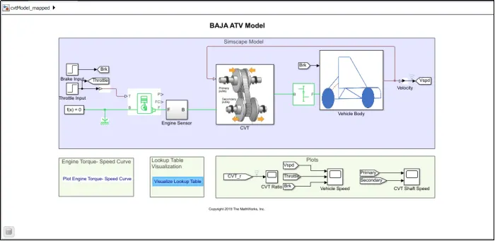
Fig 2.2 BAJA ATV model with look-up table
In the model with look up table vehicle speed is connected to the look-up table for getting the CVT ratio. Here the CVT ratio will be based on the vehicle speed.
After running the model the output is as shown below
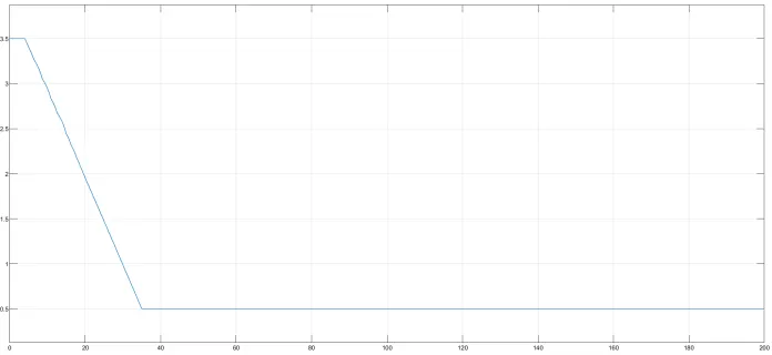
Fig 2.3 scope output of CVT ratio
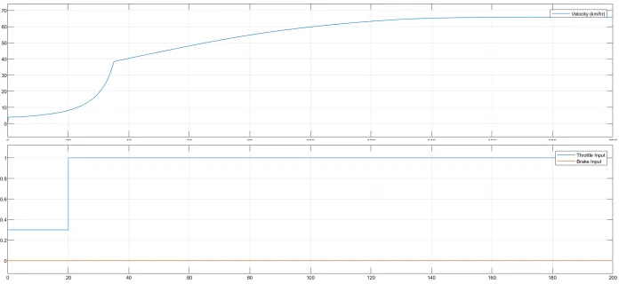
Fig 2.4 Scope output of Engine velocity, throttle input and brake input
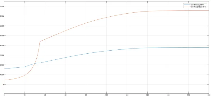
Fig 2.5 scope output of CVT primary and secondary RPM
From observing the both the outputs without look up table(fig 1.7) and with look up (fig 2.5) both the outputs are almost same because throttle is constant and acceleration is constant.
By using the dash board we can change the speed with respect to time so we can observe the difference.
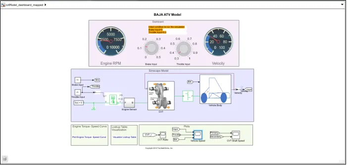
Fig 2.6 BAJA ATV model with look up table and dash board
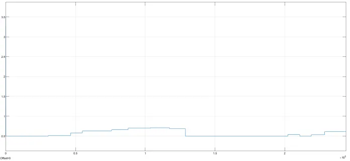
Fig 2.7scope output CVT ratio
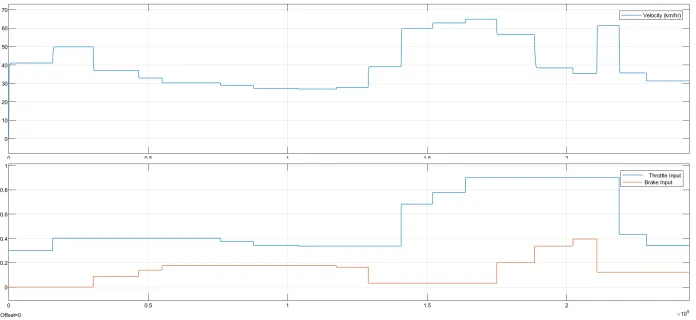
Fig 2.8 scope output Engine , throttle input and brake input
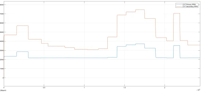
Fig 2.9 Scope output of CVT primary and secondary
Here is the output of the BAJA ATV model with look up table. The difference between the both is in the model without look up table the CVT ratio will depend on time once the time passes even speed decreases the gear ratio will not increase. In case of model with look up table the CVT ratio is based on the vehicle speed so as speed decreases CVT ratio will increase.
RESULTS
Studied and prepared the technical report by simulating BAJA ATV model with and without Look up table
EXTERNAL LINKS