Project-1: Powertrain for aircraft in runways
1)
AIM
To Search and list out the total weight of various types of Aircraft.
EXPLANATION
The different terms represent different weights or masses. For each flight, the weights are taken into account for several reasons.
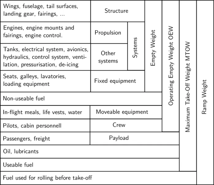
1.Manufacturer's empty weight (MEW) Licensed Empty Weight:
It is the weight of the aircraft "as built" and includes the weight of the structure, power plant, furnishings, installations, systems and other equipment that are considered an integral part of an aircraft.
This excludes any baggage, passengers, or usable fuel.
2.Zero-fuel weight (ZFW)
This is the total weight of the airplane and all its contents (including unusable fuel), but excluding the total weight of the usable fuel on board.
As a flight progresses and fuel is consumed, the total weight of the airplane reduces, but the ZFW remains constant.
3.Maximum zero fuel weight (MZFW)
Maximum zero fuel weight (MZFW) is the maximum weight allowed before usable fuel and other specified usable agents (engine injection fluid, and other consumable propulsion agents) are loaded.
4.Operating empty weight (OEW) (Roughly equivalent to basic empty weight on light aircraft)
It is the basic weight of an aircraft including the crew, all fluids necessary for operation such as engine oil, engine coolant, water, unusable fuel and all operator items and equipment required for flight but excluding usable fuel and the payload.
Payload
It is the carrying capacity of an aircraft. It includes cargo, people, extra fuel. In the case of a commercial airliner, it may refer only to revenue-generating cargo or paying passengers.
5.Maximum takeoff weight (MTOW)
This is the maximum weight at which the pilot of the aircraft is allowed to attempt to take off.
6.Regulated takeoff weight (RTOW)
Depending on different factors (e.g. flap setting, altitude, air temperature, length of runway), RTOW or maximum permissible takeoff weight varies for each takeoff. It can never be higher than MTOW. More information is on this answer.
7.Maximum landing weight (MLW)
This maximum weight at which an aircraft is permitted to land3.
The following image depicts takeoff weight components.
RESULTS
Listed the various types of weights of an aircraft.
2)
AIM
To differentiate between ground speed and air speed.
EXPLANATION
airspeed is simply the speed at which an aircraft is moving relative to the air it is flying in. As such, it’s also the speed at which the air is flowing around the aircraft’s wings.
Ground speed, on the other hand, is the aircraft’s speed relative to the ground. One thing that should be noted here is that it’s its horizontal rather than vertical speed – an aircraft climbing completely vertically would have a ground speed of zero.
In other words, while airspeed is what determines whether there is enough airflow around an aircraft to make it fly, ground speed is what determines how fast an aircraft will get to its destination.
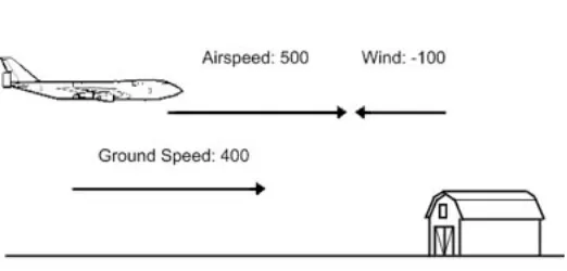
The relationship between airspeed and ground speed is fairly simple. Ground speed is simply the sum of airspeed and wind speed.
If the aircraft is flying in the same direction as the wind is blowing, the aircraft experiences tailwind, and its ground speed is higher than its airspeed. On the other hand, if the wind is blowing against the direction the aircraft is traveling in, the aircraft experiences headwind, and its ground speed is lower than its airspeed.
3)
AIM
To know why it is not recommended to use aircraft engine power to move it on the ground at Airport.
EXPLANATION
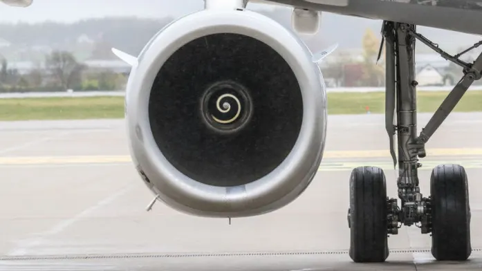
commercial airplanes are equipped with engines rated from 18,000 to nearly 100,000 lb of thrust levels for safe takeoff, flight, and landing over a wide range of temperatures, altitudes, gross weights, and payload conditions. However, the exhaust wake from these engines can pose hazards in commercial airport environments. Operators and airport authorities must carefully consider these hazards and the resulting potential for injury to people and damage to or caused by baggage carts, service vehicles, airport infrastructure, and other airplanes.
4)
How an aircraft is pushed to runway when its ready to take off ?
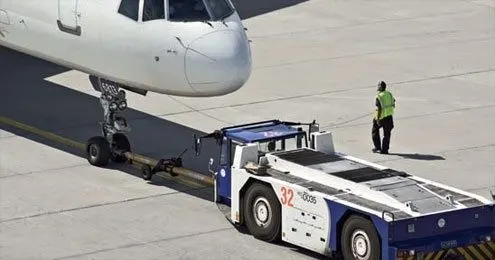
pushback is an airport procedure during which an aircraft is pushed backwards away from an airport gate by external power. Pushbacks are carried out by special, low-profile vehicles called pushback tractors or tugs.
Pushbacks at busy aerodromes are usually subject to ground control clearance to facilitate ground movement on taxiways. Once clearance is obtained, the pilot will communicate with the tractor driver to start the pushback. To communicate.
Since the pilots cannot see what is behind the aircraft, steering is done by the pushback tractor driver and not by the pilots. Depending on the aircraft type and airline procedure, a bypass pin may be temporarily installed into the nose gear to disconnect it from the aircraft's normal steering mechanism.
Once the pushback is completed, the towbar is disconnected, and any bypass pin removed. The ground handler will show the bypass pin to the pilots to make it clear that it has been removed. The pushback is then
5)
Learn about take off power, tyre design, rolling resistance, tyre pressure, brake forces when landing
Take off power: Takeoff is the phase of flight in which an aerospace vehicle leaves the ground and becomes airborne. Take off power is a power required to take off the flight after the towing.
Rolling resistance: it is the force resist the aircraft tyres to roll over the run way.
Rolling resistance of an aircraft on a dry runway will between the 0.03 to 0.08 based on the aeroplane.
Tyre pressure: air pressure inside the tire is called the tire pressure. Tyre pressure for an aircraft is upto 300 PSi. Even higher for the jet aircrafts.
Break forces when landing
Aircraft disc brakes in the landing gear, used to brake the wheels while touching the ground. These brakes are operated hydraulically or pneumatically. In most modern aircraft they are activated by the top section of the rudder pedals. In some older aircraft the bottom section is used instead. Levers are used in a few aircraft. Most aircraft are capable of differential braking.
Thrust reversers, that allow thrust from the engines to be used to slow the aircraft.
Air brakes, dedicated flight control surfaces that work by increasing drag
6)
AIM
To calculate the force and power required to push / pull an aircraft by a towing vehicle With necessary assumptions.
DESCRIPTION
Push back truck will push the aircraft from the airport terminal with the constant velocity and the there will be no slope on the surface. Therefore force required by the truck will be aerodynamic drag force and rolling resistance force.
Here truck need to overcome rolling resistance and aerodynamic drag of both aeroplane and truck
F=Frr(a)+Frr(t)+Fad(a)+Fad(t)
Where Frr(a)=rolling resistance of aeroplane
Frr(t)=rolling resistance of push back truck
Fad(a)=aerodynamic drag force of aeroplane
Fad(t)=aerodynamic drag force of push back truck truck
Aerodynamic drag force is very low compared to rolling resistance so lets ignore it
Therefore F=Frr(a)+Frr(t)
Frr=μrrmg
Where μrr=rolling resistance co efficient
m=mass of vehicle
g=gravitational constant 9.8 m/sec
Power required will be P=F*v
F=force
v=velocity
CALCULATION
Assumption for the designing the push back truck vehicle
Mass of the towing tractor = 50000 kg
Rolling resistance co efficient =0.007
Mass of the aircraft =575000(Ramp weight)
Rolling resistance co efficient =0.004
F=Frr(a)+Frr(t)
F=μrr(a)m(a)g+μrr(t)m(t)g
F=0.004*575000*9.8+0.007*50000*9.8
F=25970 N
F=25.97 KN
Power required for moving air craft at 20 kmph(5.67 m/sec)
P=25.97*5.67 = 144.26 KW
RESULTS
Calculated the force and power required by the towing vehicle to push back the air craft.
7)
AIM
To Design an electric powertrain with type of motor, it’s power rating, and energy requirement to fulfill aircraft towing application. Estimate the duty cycle range to control the aircraft speed from zero to highest. Make all required assumptions. Prepare a table of assumed parameters. Draw a block diagram of powertrain.
DESCRIPTION
lets take the force and power required from the above example for designing of the power train.
Torque required at the wheels= total force* radius of tyre
Motor torque = torque at wheels/( gear ratio* gear efficiency)
Motor power = output power/ efficiency
Energy= power * time in hours
Duty cycle=required power/ rated power
CALCULATION
From the above problem assumptions we got F=25.97 KN and P=72.13 KW
Lets assume tyre radius=27/2 inches=0.68/2 meters=0.34
Gear ratio=9
Motor efficiency=0.90
Gear transmission efficiency=0.85
Time for pushing the aircraft back=30 mins= 0.5 hrs
Torque required at wheels = force* radius=25.97*0.34= 8.83 KN-m
Motor torque=torque at wheels/( gear ratio* gear efficiency)=8.83/(9*0.85)=1.14 KN-m
Motor power=output power/efficiency
=144.26/0.9*0.8
=188.57 KW
Motor designed need to be more power than 188.57 KW
Lets take the motor with the capacity of 200KW
Duty cycle=required power/rated power = 188.57/200
=0.94
Duty cycle for the vehicle is 0 to 94 %
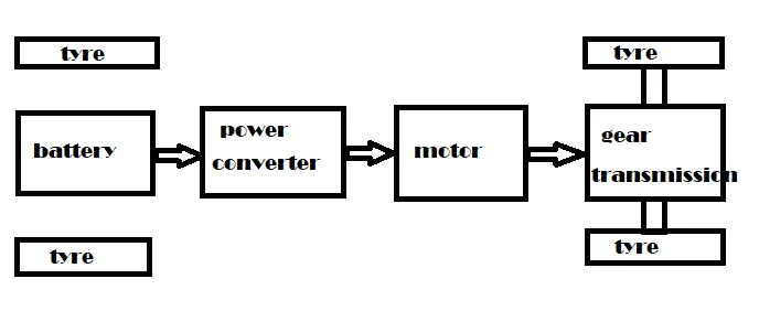
Block diagram of power train
RESULT
designed the power train for push back tractor