Project 1
Aim
To design and simulate any three DC-DC converter and to show necessary waveforms.
Description
The topologies selected to simulate are as below



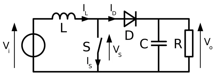
Boost Converter:
A boost converter (step-up converter) is a DC-to-DC power converter that steps up voltage from its input (supply) to its output. It is a class of switched-mode power supply (SMPS) containing a diode, a transistor, a capacitor and inductor.
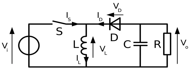
Inverting Buck boost Converter
The output voltage is of the opposite polarity than the input. This is a switched-mode power supply with a similar circuit topology to the boost converter and the buck converter. The output voltage is adjustable based on the duty cycle of the switching transistor.
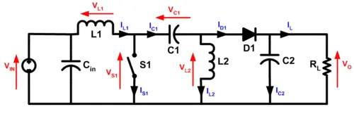
SEPIC DC-DC Converter
The single-ended primary-inductor converter (SEPIC) is a type of DC/DC converter that allows the electrical potential (voltage) at its output to be greater than, less than, or equal to that at its input. The output of the SEPIC is controlled by the duty cycle of the control switch (S1). A SEPIC is essentially a boost converter followed by an inverted buck-boost converter, therefore it is similar to a traditional buck-boost converter.
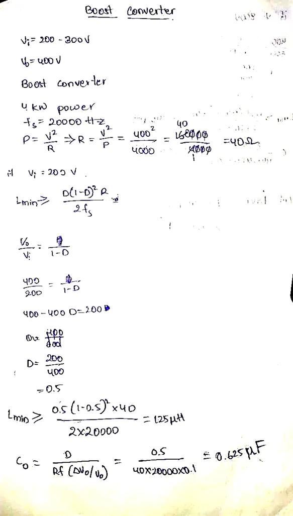
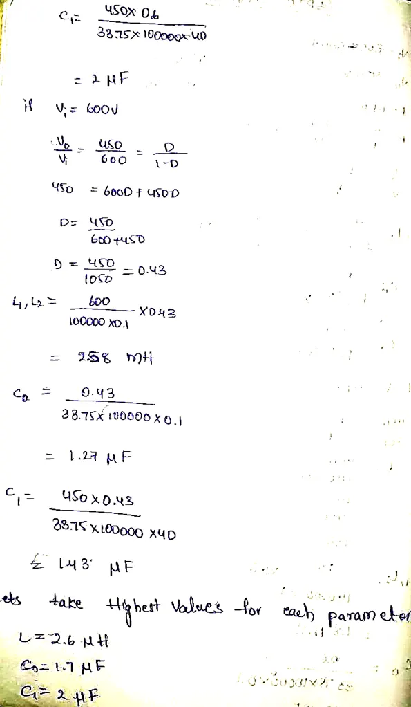
Design of Capacitors and Inductors
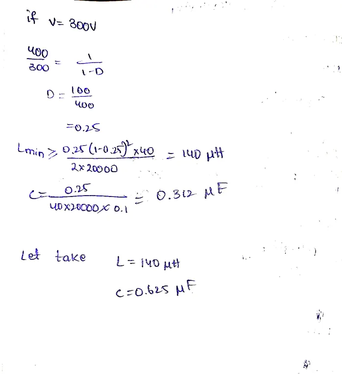
- Boost Converter
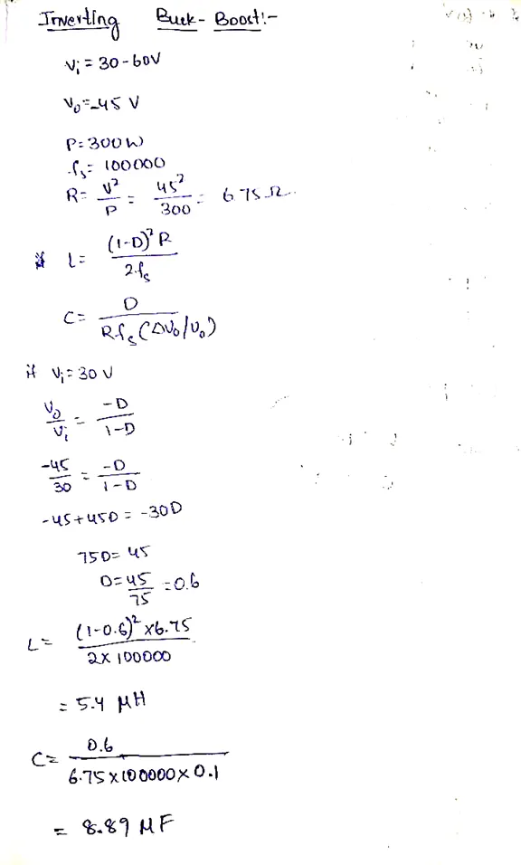
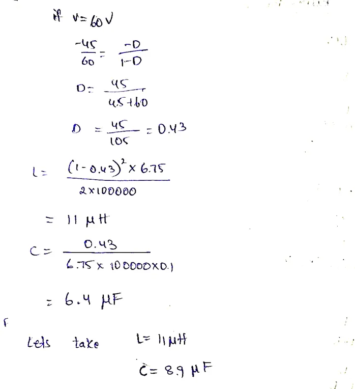
Inverting Buck boost
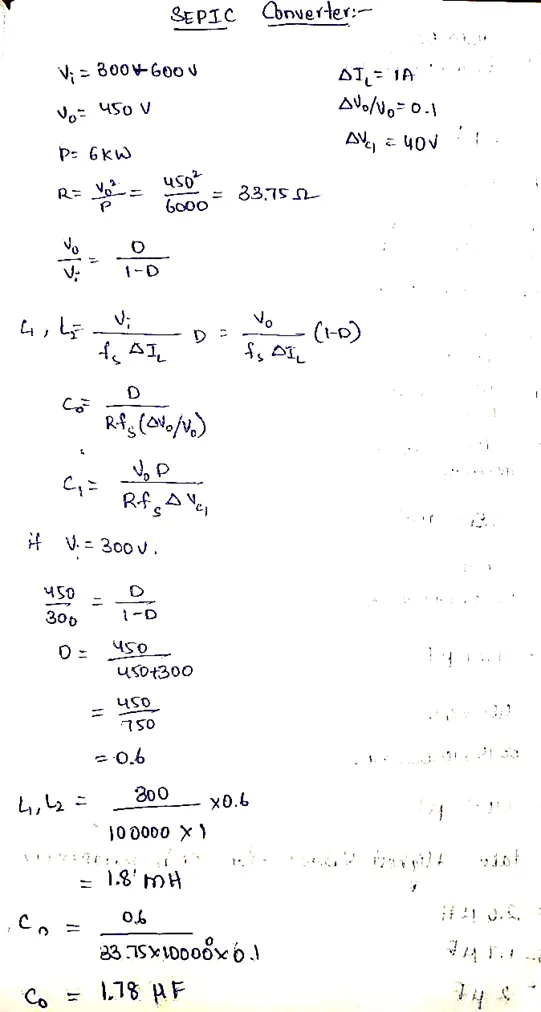
SEPIC Converter
Simulation
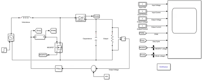
Boost Converter
Procedure
- Design the boost converter model as above in the MATLAB Simulink.
- Set the parameters of voltage source, Inductor, Capacitor and resistance values as per the question and design.
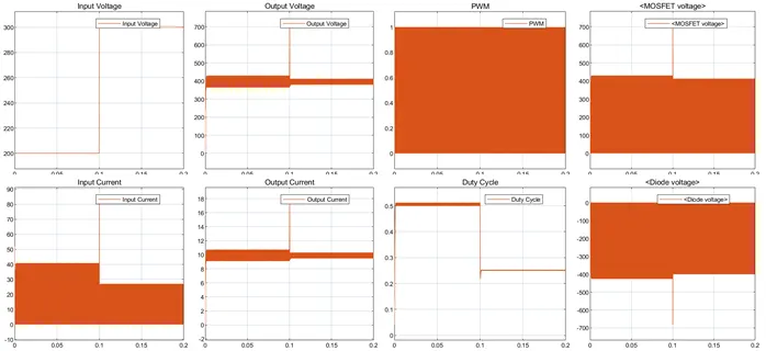
- In the above circuit the input voltage is changing from 200 to 300 at 0.1 sec.
- Now run the model for 0.2 sec and observe the results.
Output
Output after zooming
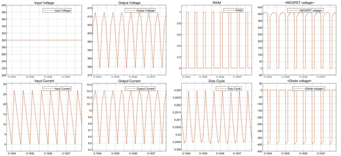
From above output we can observe that output voltage is fluctuating around 400 v and peak to peak voltage is 412-379= 33 V. we can further reduce the peak to peak voltage by increasing the output Capacitance.
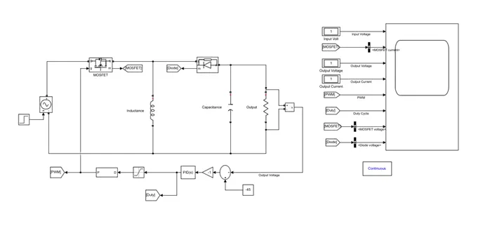
Inverting Buck-Boost Converter.
Procedure
- Design the boost converter model as above in the MATLAB Simulink.
- Set the parameters of voltage source, Inductor, Capacitor and resistance values as per the question and design.
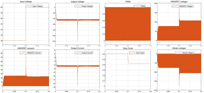
- In the above circuit the input voltage is changing from 30 to 60 at 0.1 sec.
- Now run the model for 0.2 sec and observe the results.
Output
Output after zooming
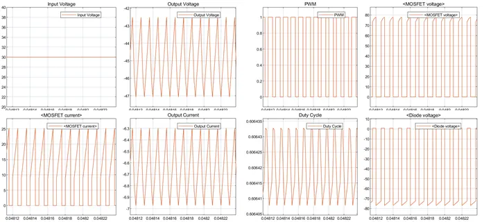
From above output we can observe that output voltage is fluctuating around -45 v and peak to peak voltage is -42.5+47= 4.5 V. we can further reduce the peak to peak voltage by increasing the output Capacitance.
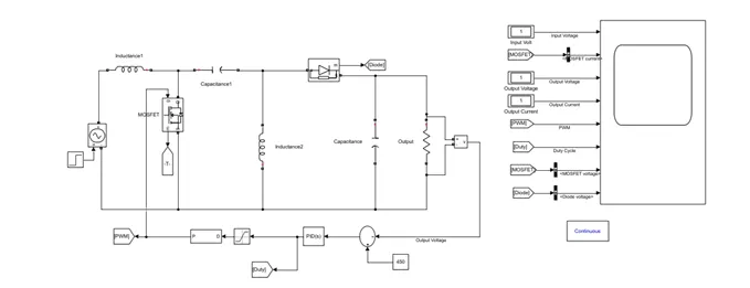
SEPIC DC-DC Converter
Procedure
Procedure
- Design the boost converter model as above in the MATLAB Simulink.
- Set the parameters of voltage source, Inductor, Capacitor and resistance values as per the question and design.
- In the above circuit the input voltage is changing from 300 to 600 at 0.1 sec.
- Now run the model for 0.2 sec and observe the results.
Output
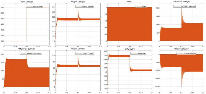
Output after zooming
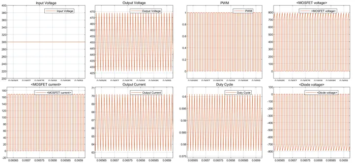
From above output we can observe that output voltage is fluctuating around 450 v and peak to peak voltage is 474-427= 47V. we can further reduce the peak to peak voltage by increasing the output Capacitance.
Result
Designed and simulated three DC-DC converter and shown necessary waveforms.
Link for folder with model
https://drive.google.com/drive/folders/1oySSYeTEv133OdlDldQx-BLA_LP2q431?usp=sharing