Project
AIM: To carry out a system-level simulation of an all-terrain vehicle used in BAJA
OBJECTIVE:
To prepare detailed technical report on the BAJA (ATV) model with the Continous Variable Transmission (CVT). for the below cases
1) Simulink model of ATV without dashboard in open loop
2)Simulink model of ATV with dashboard in closed loop
DEFINITION OF ATV
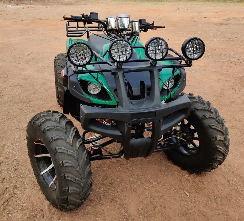
An all-terrain vehicle (ATV) is defined as a motorized off-highway vehicle designed to travel on four low-pressure or non-pneumatic tires, having a seat designed to be straddled by the operator and handlebars for steering control. ATVs are subdivided into two types as designated by the manufacturer. Type I ATVs are intended by the manufacturer for use by a single operator and no passenger. Type II ATVs are intended by the manufacturer for use by an operator and a passenger, and are equipped with a designated seating position behind the operator. Similarly, riders must also consider the various ATV sizes.
What is a CVT?
A CVT, or continuously variable transmission, seamlessly changes through an unending range of effective gear ratios while you drive, whereas other kinds of mechanical transmissions offer a fixed number of gear ratios and have hard shifts between each as explained by Certified Transmission Repair. CVT transmission systems are also known as single-speed, shiftless, and stepless transmissions.
The shiftless nature of a CVT offers unparalleled flexibility that maintains constant angular velocity regardless of output speed. Additionally, a continuously variable transmission makes accelerating smooth and offers enhanced fuel economy.
How does CVT work
While a traditional transmission uses a wide variety of intricate parts to shift between a range of preset gears, most CVT systems work through a pulley system. In short, this system consists of cones at each pulley connected via a chain belt. The cones can move to increase or decrease the belt diameter to change gear ratios, allow for quick shifting into the needed ratio for increased power, and boost fuel economy.
One pulley in the CVT is connected to the engine and the other directs power to the wheels. The width of these pulleys changes based on the needed power; as one gets larger, the other gets smaller. This allows a CVT to deliver strong and seamless acceleration
SIMULINK BLOCKS USED:
- Signal Builder – The Signal Builder block allows you to create interchangeable groups of piecewise linear signal sources and use them in a model.
- Generic Engine – Represents a system-level model of spark-ignition and diesel engines suitable for use at the initial stages of modeling when only the basic parameters are available.
- Solver Configuration – The Solver Configuration block specifies the solver parameters that your model needs before you can begin the simulation.
- Mechanical Rotational Reference – The Mechanical Rotational Reference block represents a reference point, or frame, for all mechanical rotational ports.
- Goto – The Goto block passes its input to its corresponding From blocks. The input can be a real- or complex-valued signal or vector of any data type. From and Goto blocks allow you to pass a signal from one block to another without actually connecting them.
- From – The From block accepts a signal from a corresponding Goto block, then passes it as output. The data type of the output is the same as that of the input from the Goto block. From and Goto blocks allow you to pass a signal from one block to another without actually connecting them.
- Simulink PS Converter – Converts the Simulink input signal to a Physical Signal.
- PS-Simulink Converter – Converts the input Physical Signal to a Simulink output signal.
- Ideal Rotational Motion Sensor – The Ideal Rotational Motion Sensor block represents an ideal mechanical rotational motion sensor, that is, a device that converts an across variable measured between two mechanical rotational nodes into a control signal proportional to angular velocity or angle.
- Mechanical rotational Reference – The Mechanical Rotational Reference block represents a reference point, or frame, for all mechanical rotational ports.
- PS terminator – Use this block to terminate physical signal outputs.
- Inertial – The block represents an ideal mechanical rotational inertia.
- Ideal Rotational Motion Sensor – The Ideal Rotational Motion Sensor block represents an ideal mechanical rotational motion sensor, that is, a device that converts an across variable measured between two mechanical rotational nodes into a control signal proportional to angular velocity or angle.
- Mechanical rotational Reference – The Mechanical Rotational Reference block represents a reference point, or frame, for all mechanical rotational ports.
- Variable Ratio Transmission – Represents a variable ratio gearbox such as implemented by mechanical belt CVT, electric, or hydraulic transmissions
- Simple Gear – Represents a fixed-ratio gear or gearbox.
- Double Shoe Brake – Represents a brake arranged as two pivoted rigid shoes symmetrically installed inside or outside a drum and operated by one actuator. The actuator force causes the shoes to exert friction torque on a shaft connected to the drum.
- Tyre – Represents the longitudinal behavior of a highway tire characterized by the tire Magic Formula.
- Vehicle Body – Represents a two-axle vehicle body in longitudinal motion. The block accounts for body mass, aerodynamic drag, road incline, and weight distribution between axles due to acceleration and road profile.
- PS Constant – This block creates a physical signal constant:
- Scope – Display signals generated during simulation.
MODEL:
1) Simulink model of ATV without dashboard in open loop
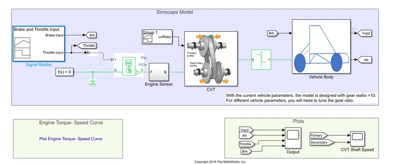
Here we are generating our own throttle and break using sinal builder and using CVT block we are giving our own gear ratio
Subsystems:
1)Engine sensor
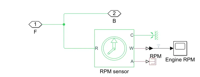
The output from the Generic Engine is the pass through the engine sensor block where it records the rpm of the engine during the simulation, which is displayed using scope and then it is forwarded towards the CVT Transmission.
2) CVT
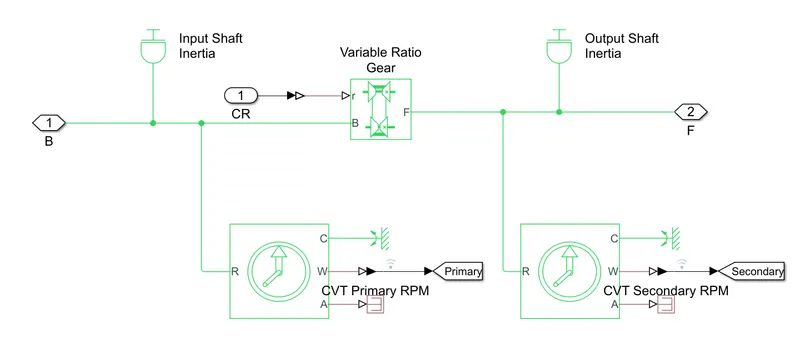
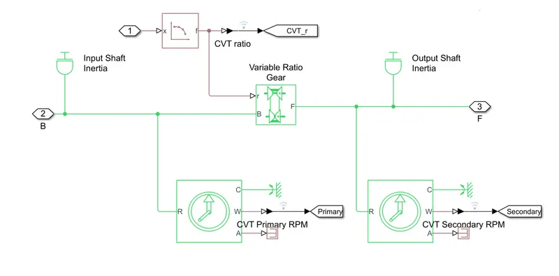
In CVT block, it takes the two inputs, one from the engine and another from the signal builder block which provides the CVT ratio.In the CVT block, there are two ideal rotational sensor blocks & two inertia blocks each for input and output shafts respectively, and then there is the Variable Ratio Gear which changes its gear ratio during the simulation according to the given CVT ratio.
3) Vehicle body
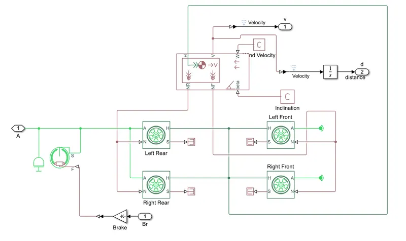
Now after the signal from the CVT block it passed through the simple gear block which we can say acts as a differential gearbox before passing to the vehicle tyres. In the vehicle body block, it requires two inputs one from the engine which we get through the simple gear block and another is the brake input and the rear tires are connected to the break
OUTPUTS:
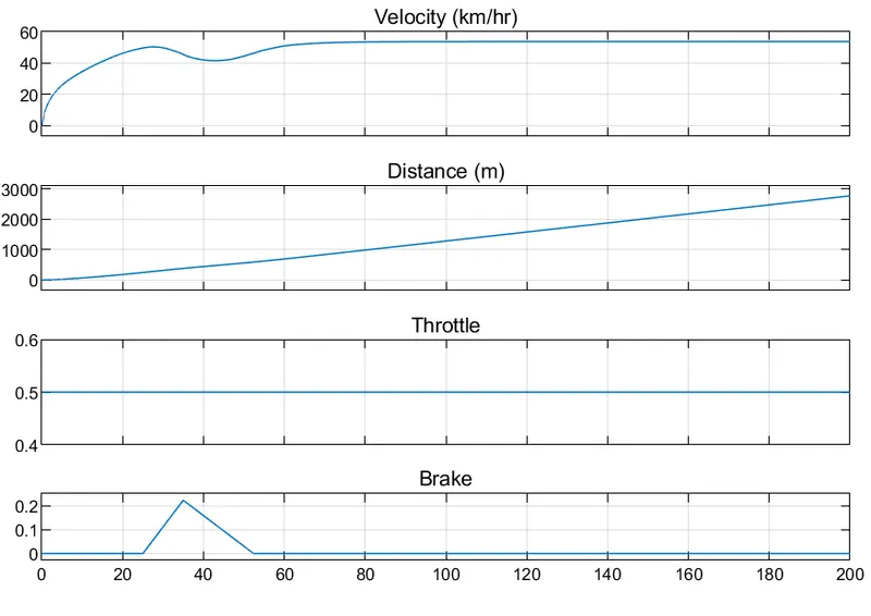
1) Velocity and distance covered based on throttle and braking
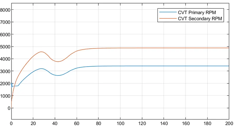
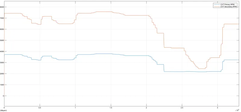
2)CVT Primary and secondary RPM Comparison
3) Engine RPM
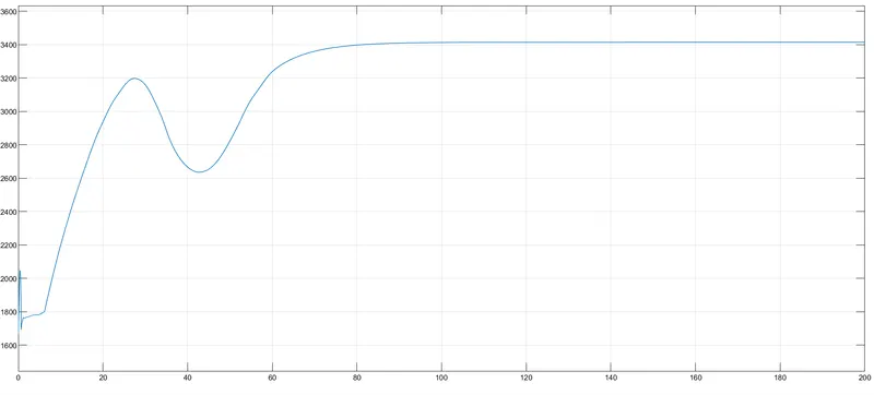
As we can see since we have applied brake between 20-45 seconds there is a dip in velocity and velocity increases after that, as a result RPM Is also increased. Initial RPM of engine is set as 1750.
2) Simulink model of ATV with dashboard in closed loop
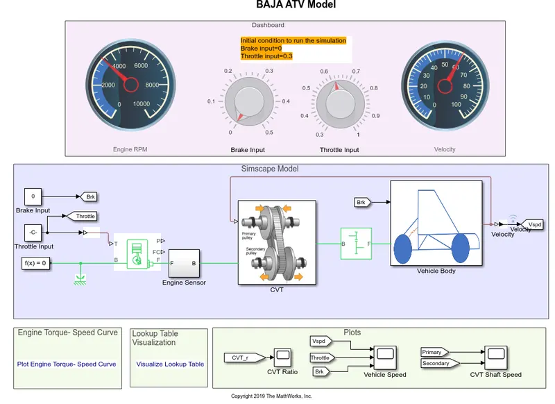
this is similar to previous model, the only difference is that here we use a dashboard so we are able to manually tune the acceleration and brake as per our requirments and also this is a closed loop one
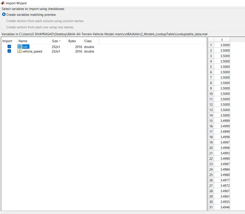
In closed loop, instead of definining the CVT ratio using lookup table like in the previous model we are using a lookup table which contains the CVT ratios
CVT block where lookup table is used:
Lookup table values:
Output:
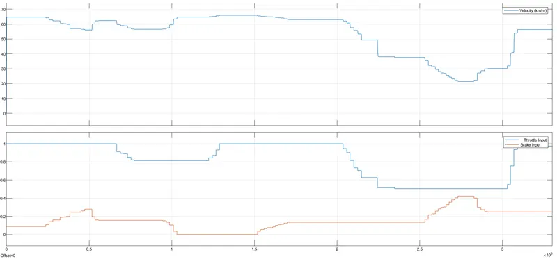
1)Change in velocity based on the variaton in throttle and brake input
2)CVT Primary and secondary RPM Comparison
3) Engine RPM
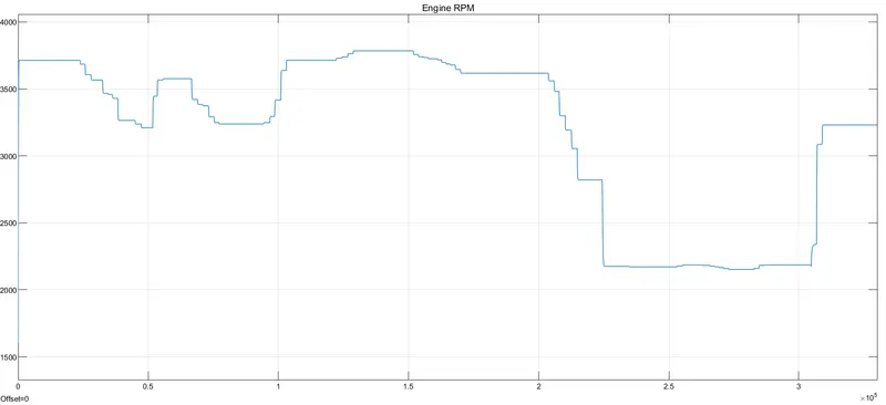
here we see based on change in throttle input and braking there is a corresponding change in Velocity, engine RPM and RPM of CVT primary and secondary
Result:
we were able to use 1st model to analyze the working of a basic CVT model and analyze the output. in second model we were able to map the throttle and braking to simulate our desired driving condition and obtain the outputs
Reference:
https://in.mathworks.com/matlabcentral/fileexchange/70576-baja-all-terrain-vehicle-atv-model