Project 1 - Wiper control system and Vehicle speed calculation for ABS using Wheel Speed sensor
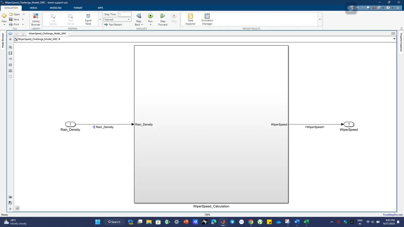
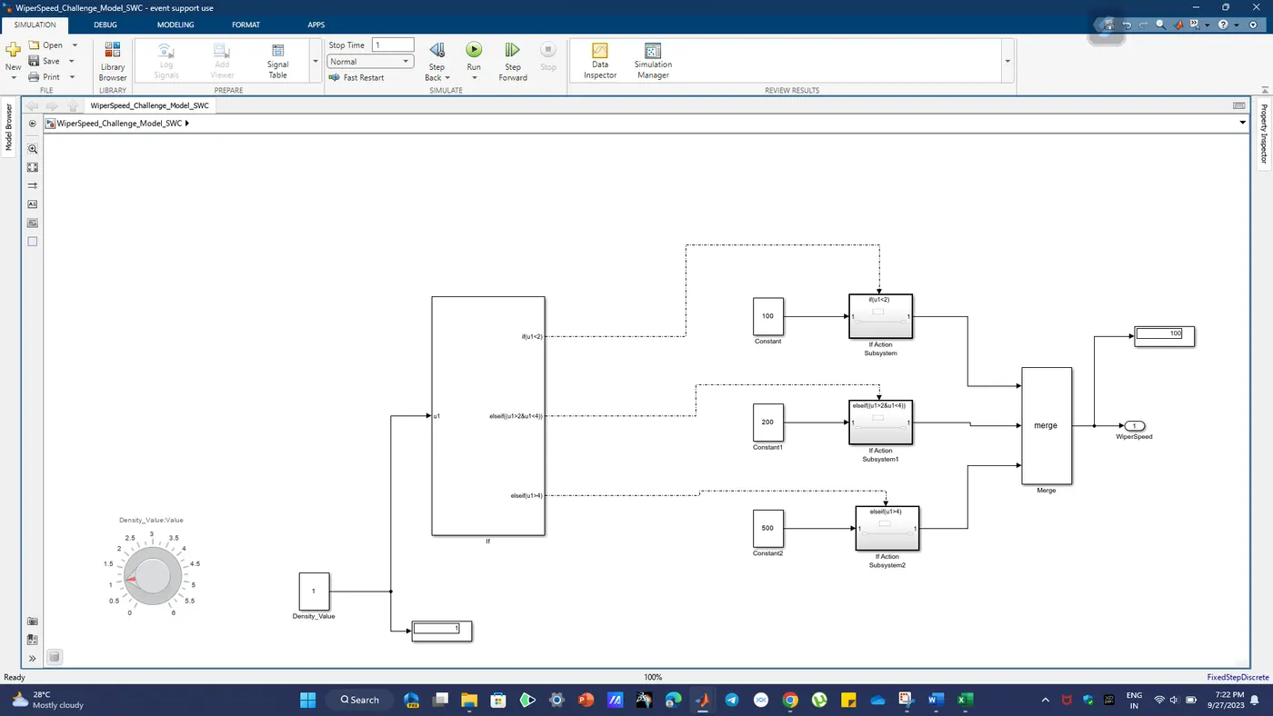
1. Requirement Editor:
Point -1: A Requirement Editor is a software tool or interface used in engineering and software development to create, manage, and document project requirements. It serves as a central repository for defining and tracking project requirements throughout the development lifecycle.
Point - 2: Requirement editors are crucial for ensuring that all project stakeholders have a clear and standardized view of the project's objectives and specifications. They facilitate communication, traceability, and compliance with industry standards and regulations.
Functionality: Requirement editors typically offer features such as requirement creation, version control, traceability, change management, and the ability to export requirements in various formats (e.g., documents, databases).
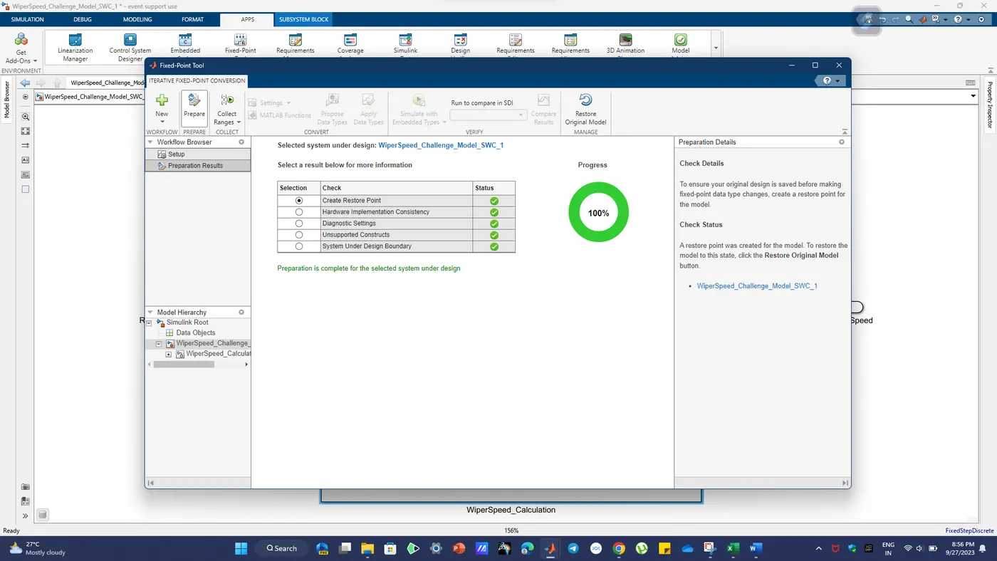
2. Fixed Tool Point Report and SLDD File Creation:
Fixed Tool Point Report:
Point -1: A Fixed Tool Point Report is a formal document that specifies a stable and well documented configuration of software tools and their settings used in a particular phase of a project. It ensures consistency and stability in the development environment.
Point - 2: Fixed tool points are essential in industries with stringent regulatory requirements, as they provide a controlled environment for development, testing, and validation.
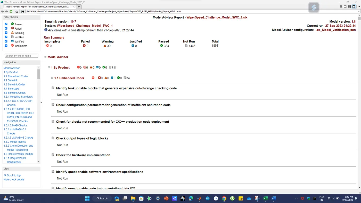
MAB Guidelines Check and Report Analysis
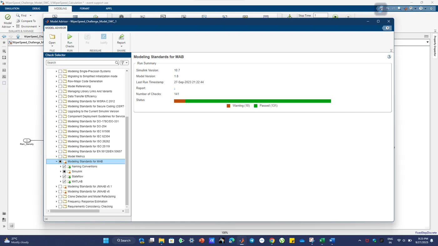
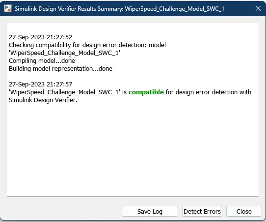
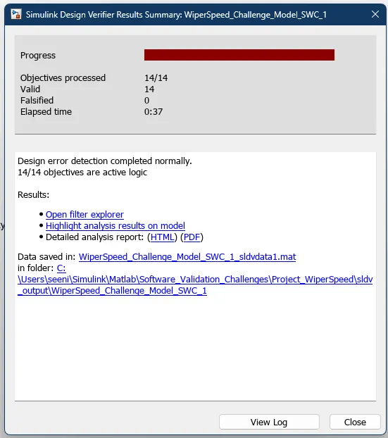
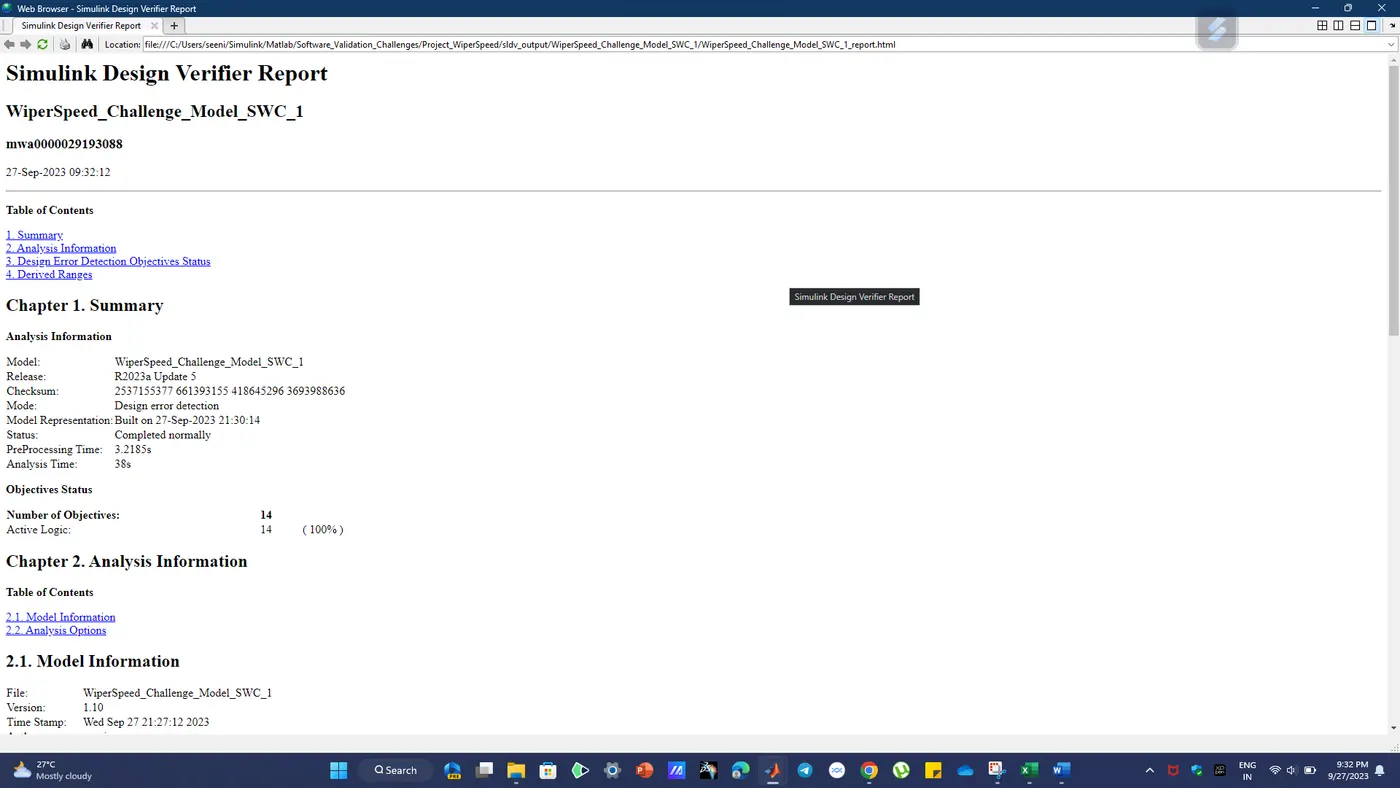
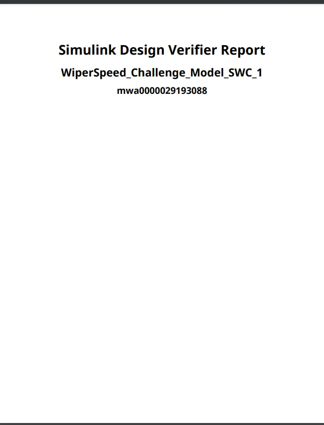
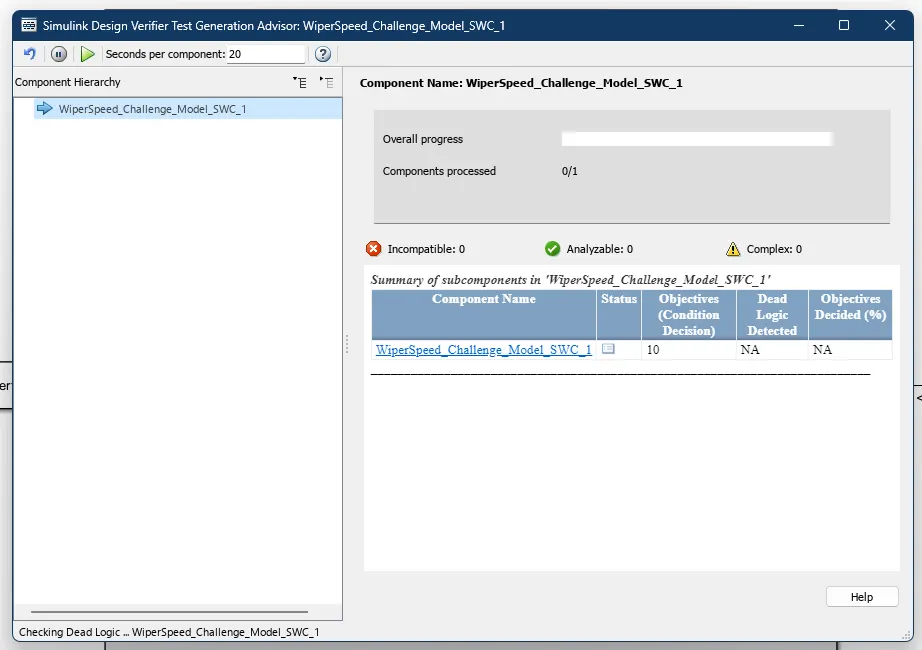
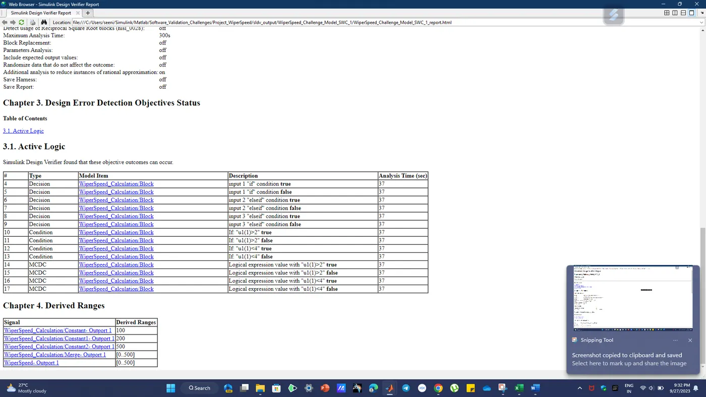
SLDV PDF Report:
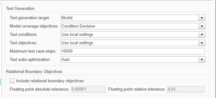
Test Generation Settings:
Functional Test Case File:
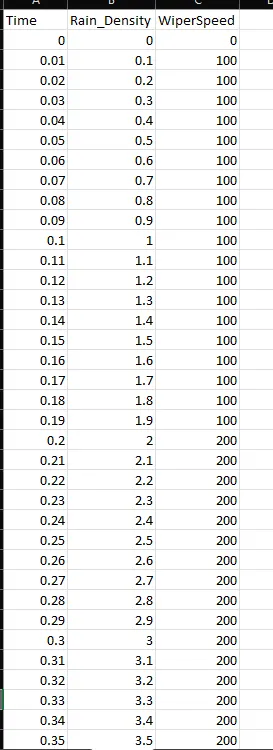
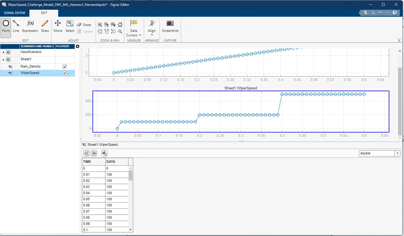
Signal Editor Block parameters and import the test case into the Signal editor block:
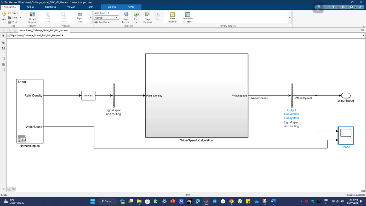
MIL harness Model:
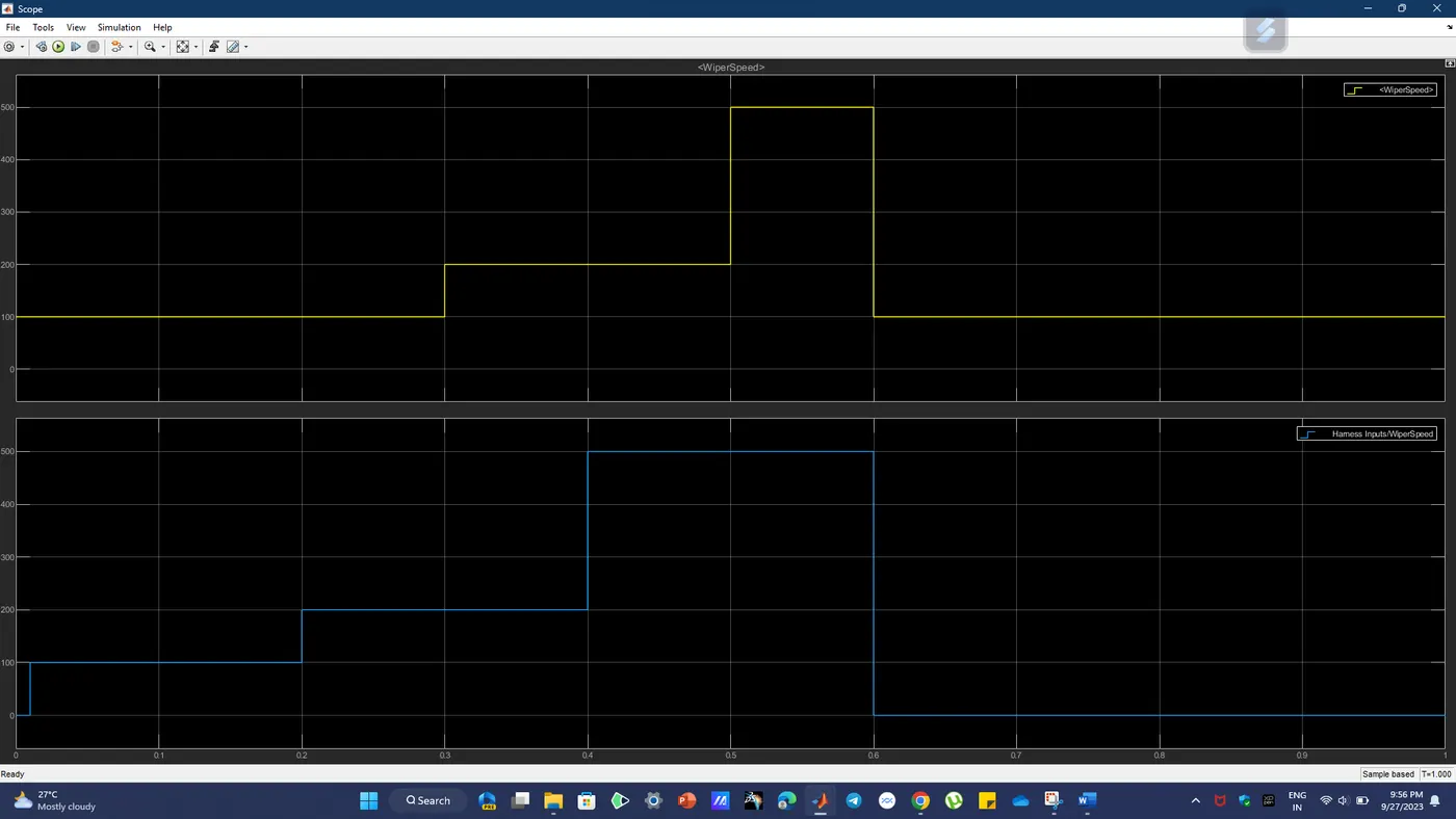
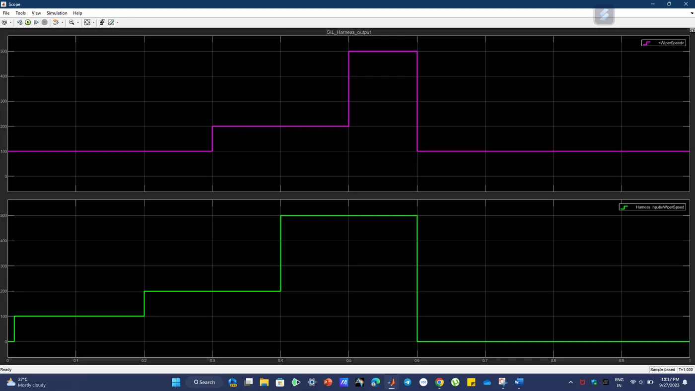
Scope Output:
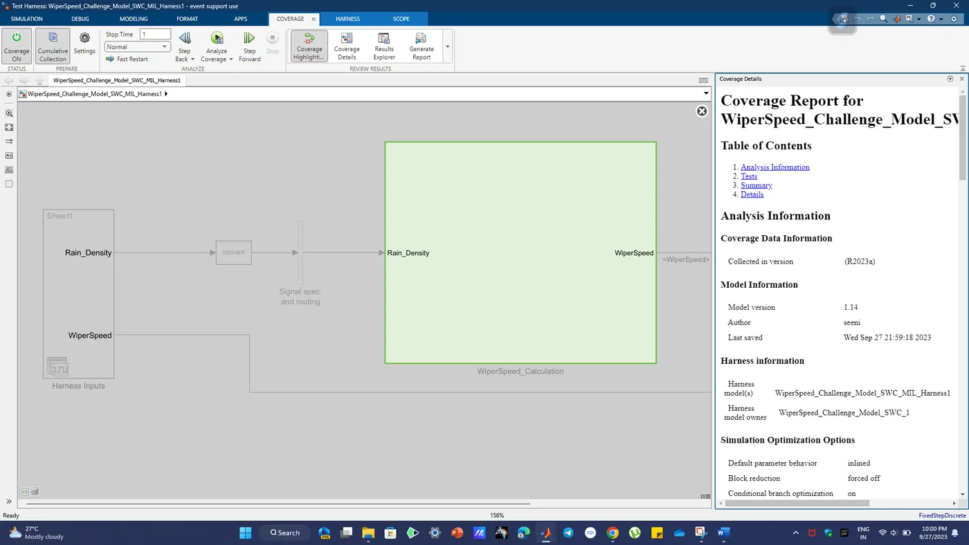
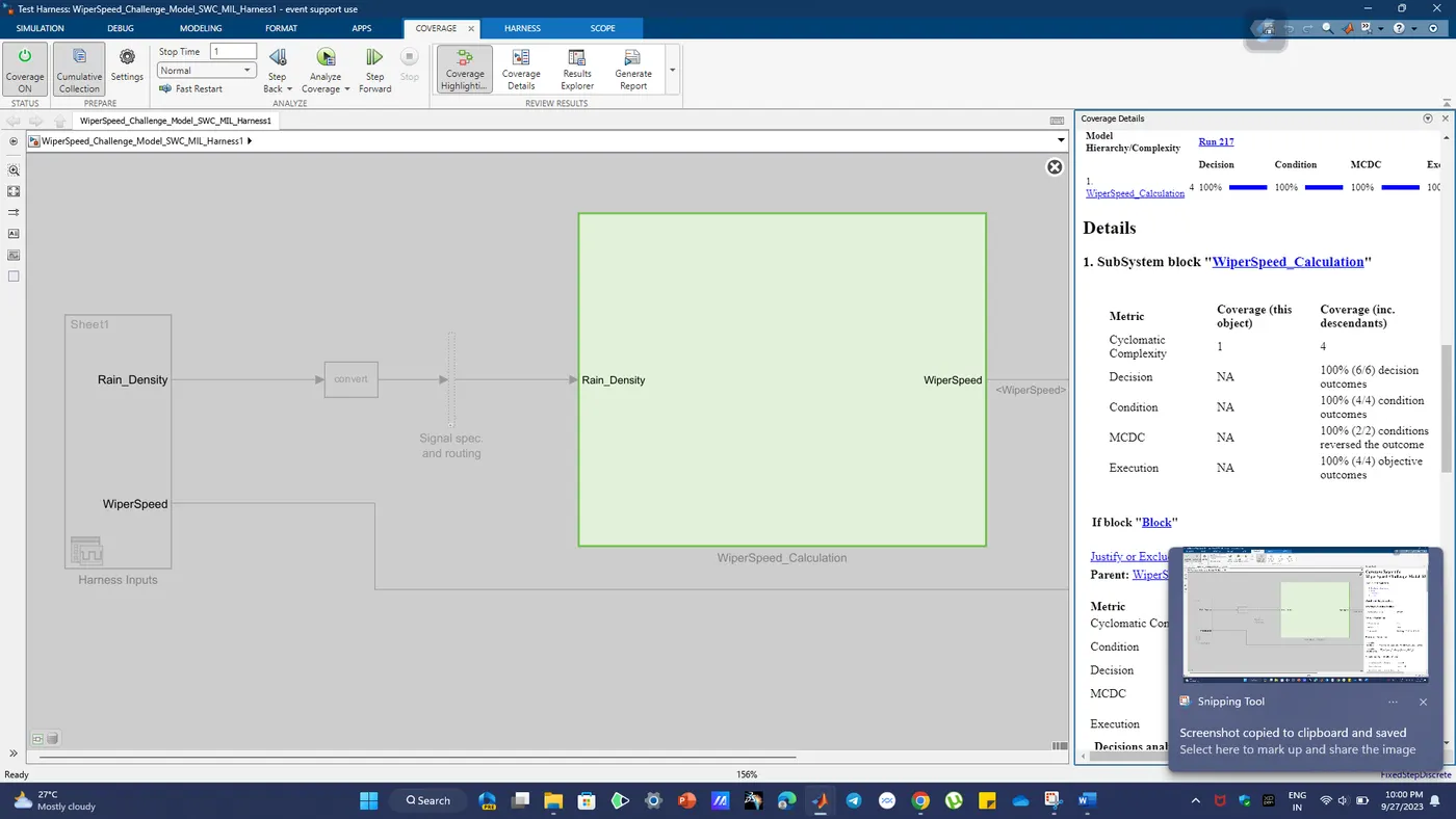
Model Coverage Analysis and Decision Coverage Analysis:
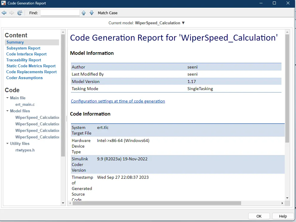
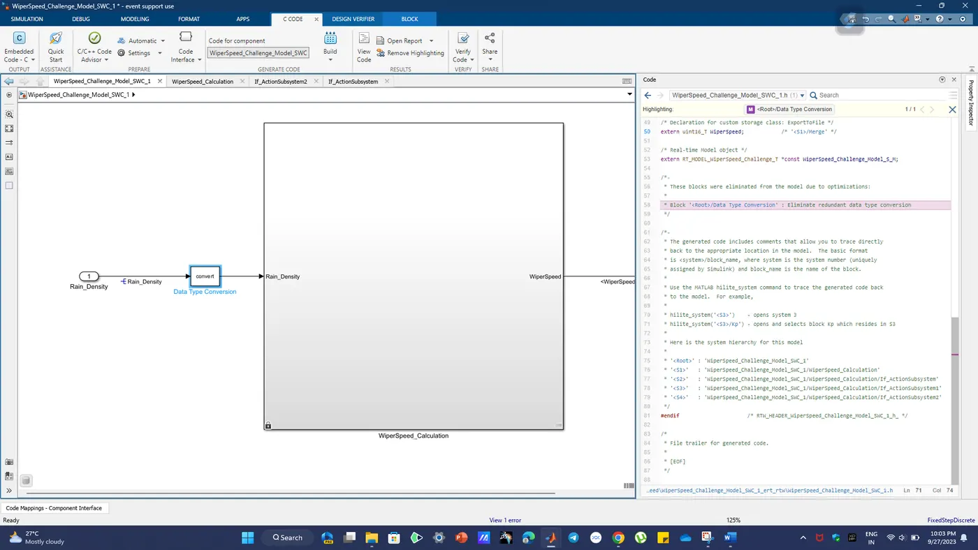
Embedded Code Generation Compatibility checking and Code generation report:
Complete C-Code for the given Model:
/*
 * Event Support License -- for demonstration use and event support.  Not
 * for government, research, commercial, or other organizational use.
 *
 * File: ert_main.c
 *
 * Code generated for Simulink model 'WiperSpeed_Challenge_Model_SWC_1'.
 *
 * Model version                  : 1.14
 * Simulink Coder version         : 9.9 (R2023a) 19-Nov-2022
 * C/C++ source code generated on : Wed Sep 27 22:02:13 2023
 *
 * Target selection: ert.tlc
 * Embedded hardware selection: Intel->x86-64 (Windows64)
 * Code generation objectives: Unspecified
 * Validation result: Not run
 */

#include
#include             /* This example main program uses printf/fflush */
#include "WiperSpeed_Challenge_Model_SWC_1.h" /* Model header file */

/*
 * Associating rt_OneStep with a real-time clock or interrupt service routine
 * is what makes the generated code "real-time".  The function rt_OneStep is
 * always associated with the base rate of the model.  Subrates are managed
 * by the base rate from inside the generated code.  Enabling/disabling
 * interrupts and floating point context switches are target specific.  This
 * example code indicates where these should take place relative to executing
 * the generated code step function.  Overrun behavior should be tailored to
 * your application needs.  This example simply sets an error status in the
 * real-time model and returns from rt_OneStep.
 */
void rt_OneStep(void);
void rt_OneStep(void)
{
  static boolean_T OverrunFlag = false;

  /* Disable interrupts here */

  /* Check for overrun */
  if (OverrunFlag) {
    rtmSetErrorStatus(WiperSpeed_Challenge_Model_S_M, "Overrun");
    return;
  }

  OverrunFlag = true;

  /* Save FPU context here (if necessary) */
  /* Re-enable timer or interrupt here */
  /* Set model inputs here */

  /* Step the model */
  WiperSpeed_Challenge_Model_SWC_1_step();

  /* Get model outputs here */

  /* Indicate task complete */
  OverrunFlag = false;

  /* Disable interrupts here */
  /* Restore FPU context here (if necessary) */
  /* Enable interrupts here */
}

/*
 * The example main function illustrates what is required by your
 * application code to initialize, execute, and terminate the generated code.
 * Attaching rt_OneStep to a real-time clock is target specific. This example
 * illustrates how you do this relative to initializing the model.
 */
int_T main(int_T argc, const char *argv[])
{
  /* Unused arguments */
  (void)(argc);
  (void)(argv);

  /* Initialize model */
  WiperSpeed_Challenge_Model_SWC_1_initialize();

  /* Attach rt_OneStep to a timer or interrupt service routine with
   * period 0.01 seconds (base rate of the model) here.
   * The call syntax for rt_OneStep is
   *
   *  rt_OneStep();
   */
  printf("Warning: The simulation will run forever. "
         "Generated ERT main won't simulate model step behavior. "
         "To change this behavior select the 'MAT-file logging' option.\n");
  fflush((NULL));
  while (rtmGetErrorStatus(WiperSpeed_Challenge_Model_S_M) == (NULL)) {
    /*  Perform application tasks here */
  }

  /* Terminate model */
  WiperSpeed_Challenge_Model_SWC_1_terminate();
  return 0;
}
has popup
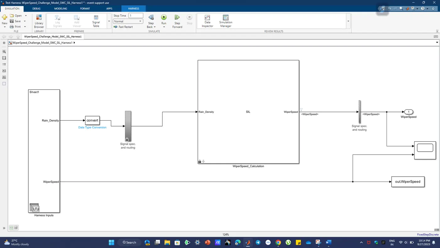
SIL harness Model with Signal Editor block
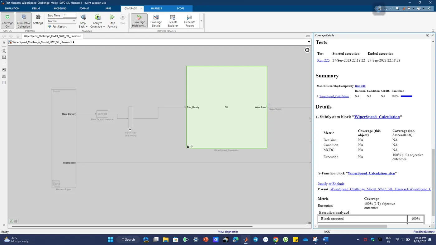
Coverage Analysis Check for Dead Logic, Integer Overflow Analysis and Test Samples:
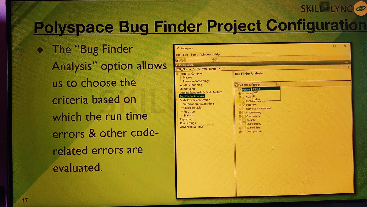
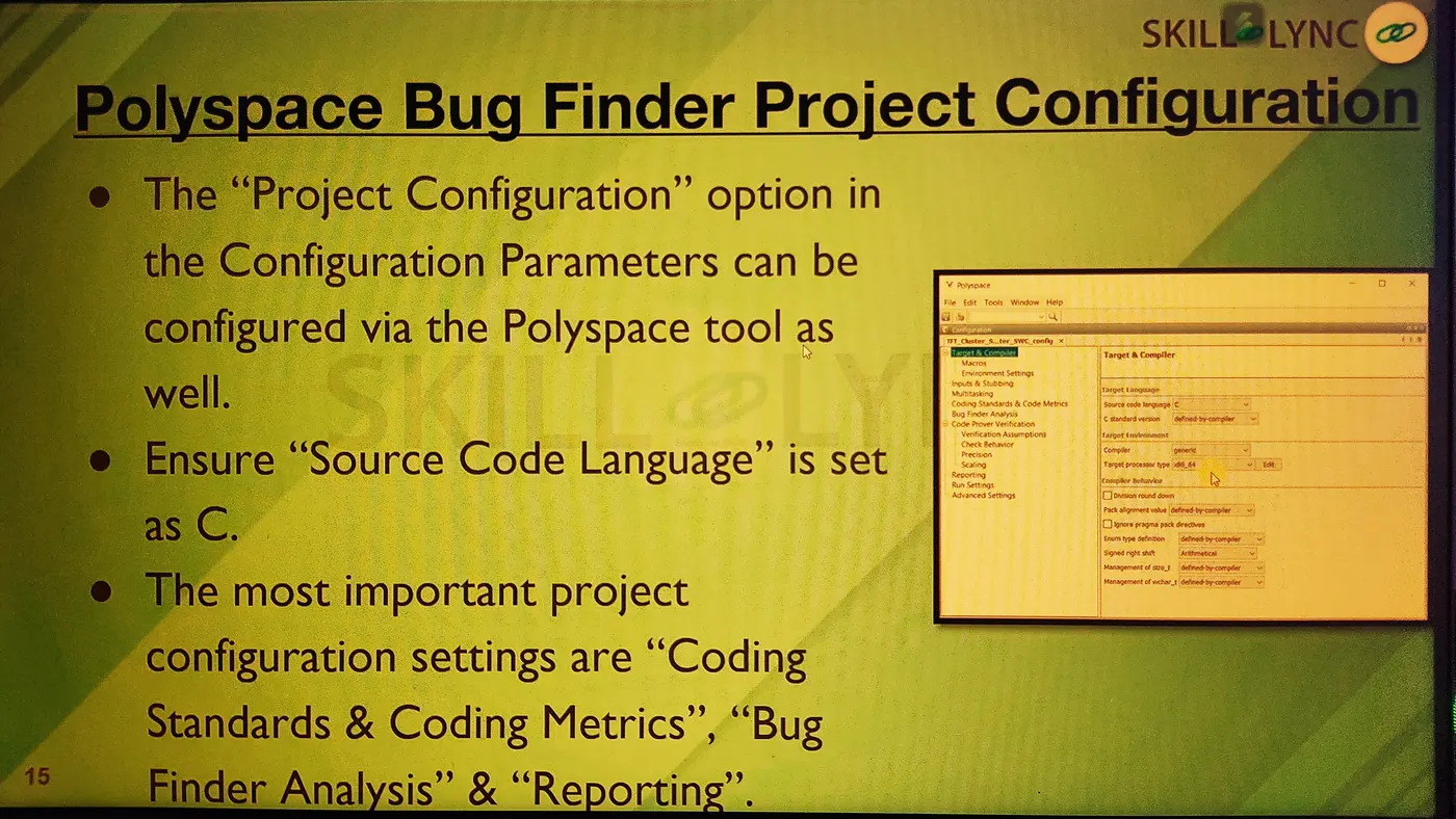
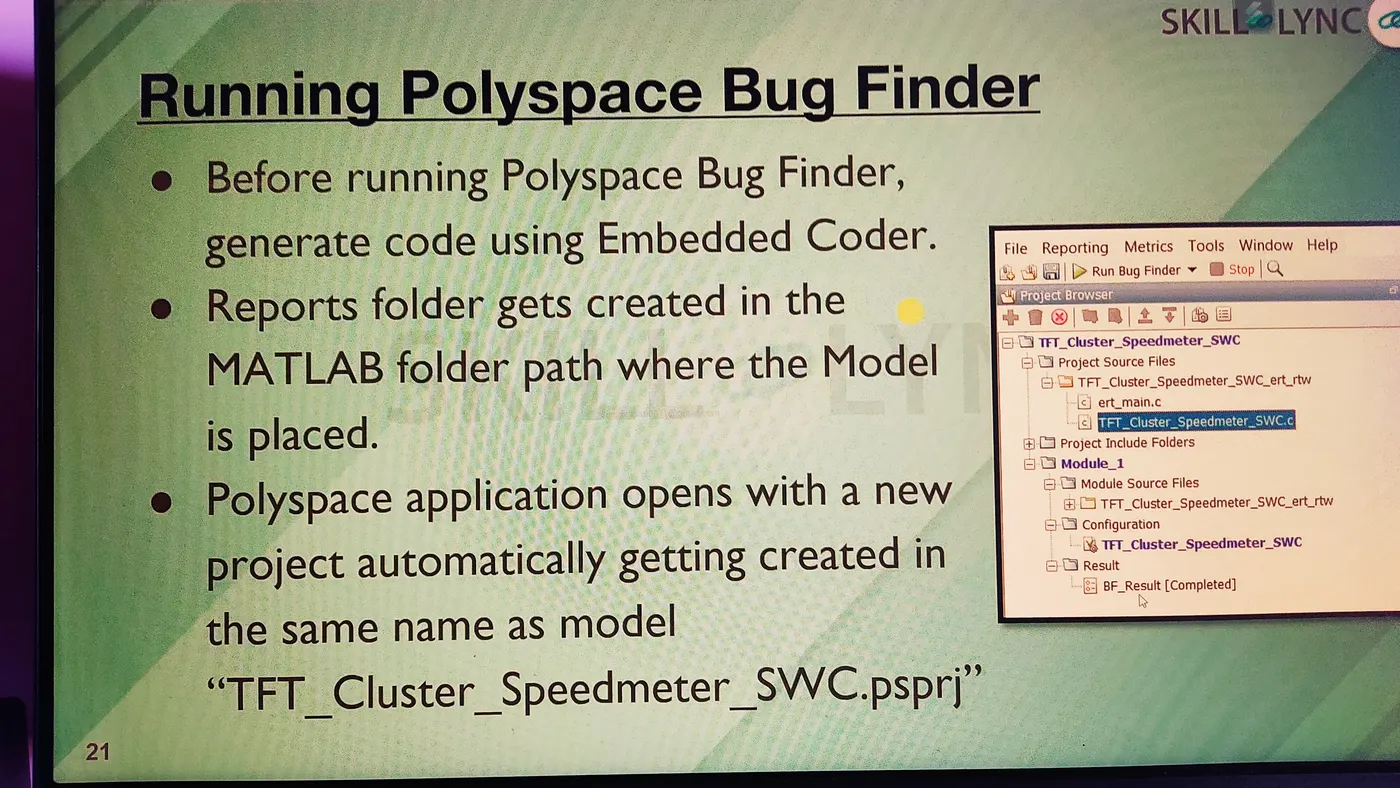
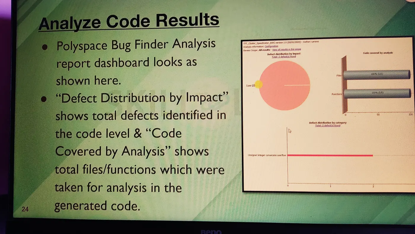
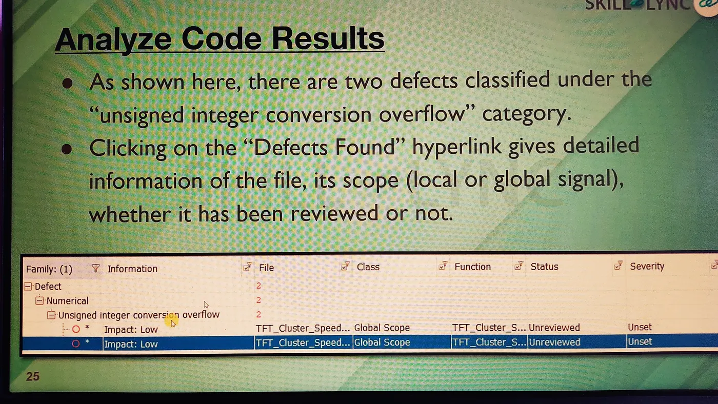
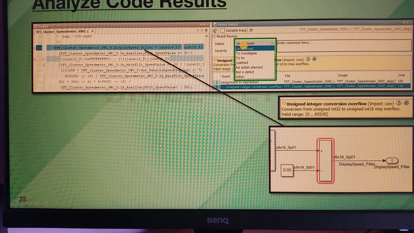
Polyspace Bug Finder and Code Prover Analysis:
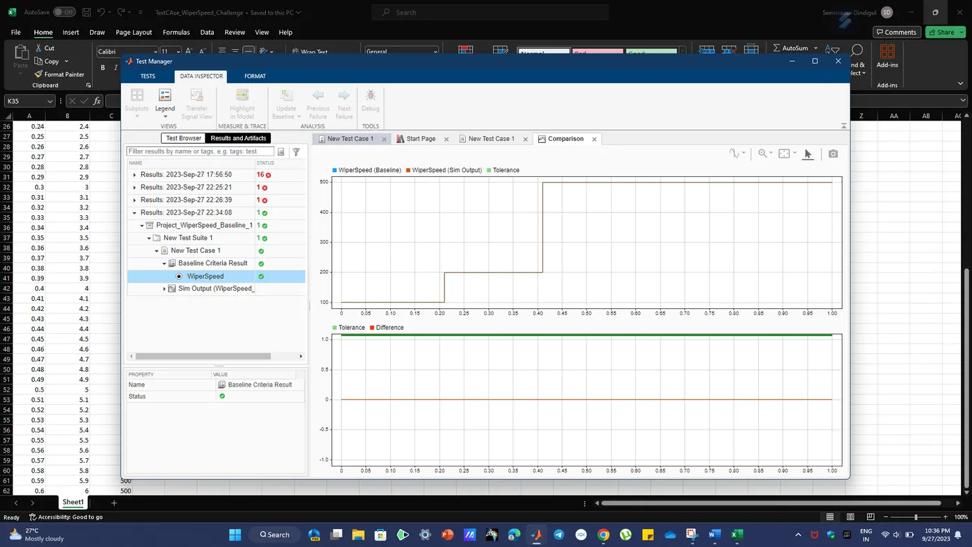
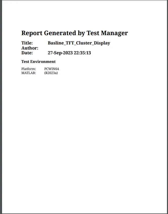
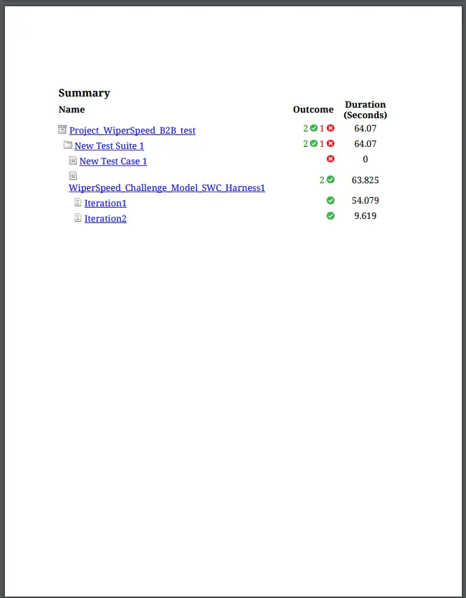
Test manger baseline Report:
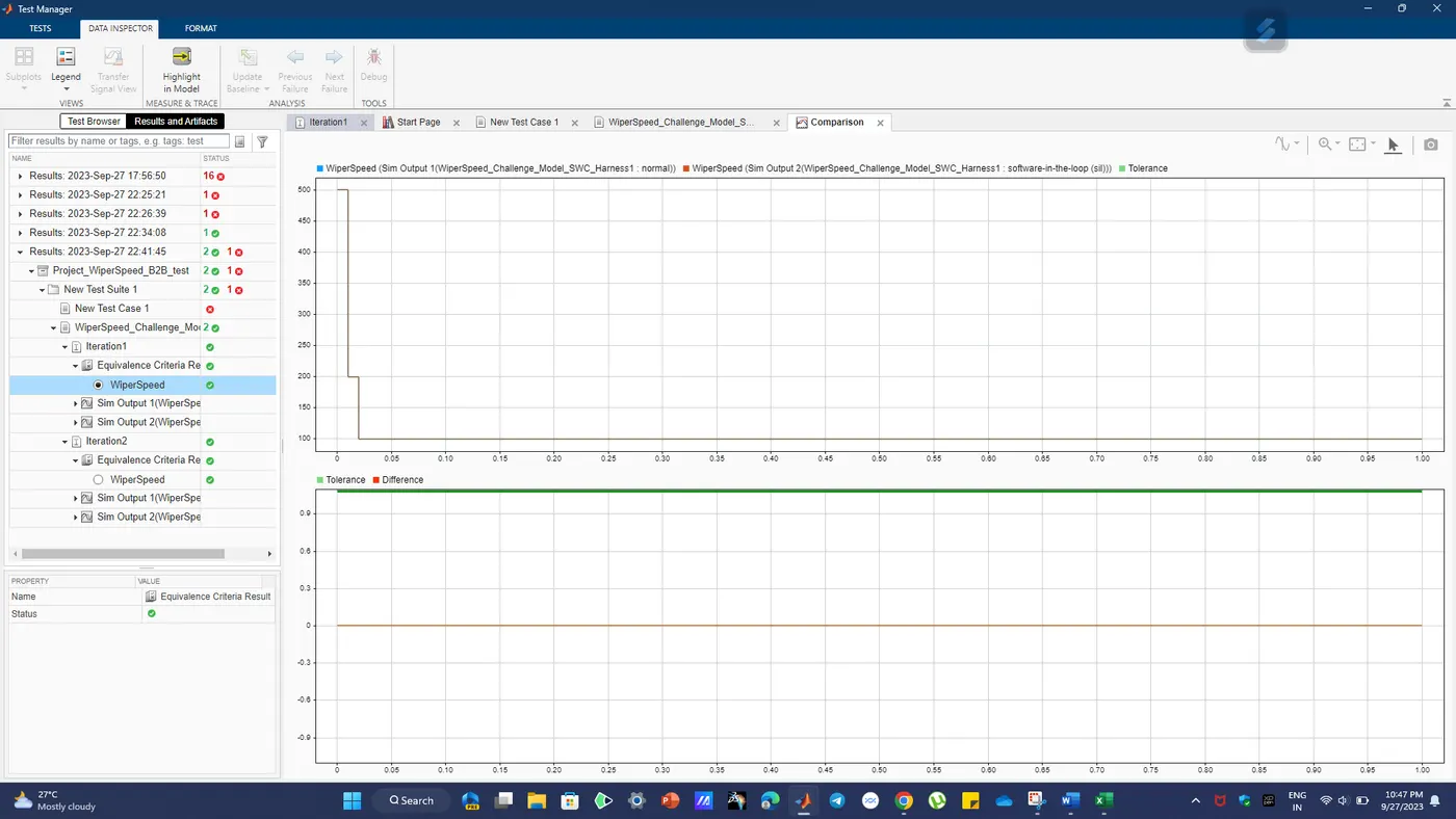
Simulink test manger back to Back Testing:
2) project - Vehicle speed calculation for ABS using Wheel Speed sensor
Aim:
To create a simulink model for vehicle speed calculation unit inside the ABS system.
Condition:
Model:
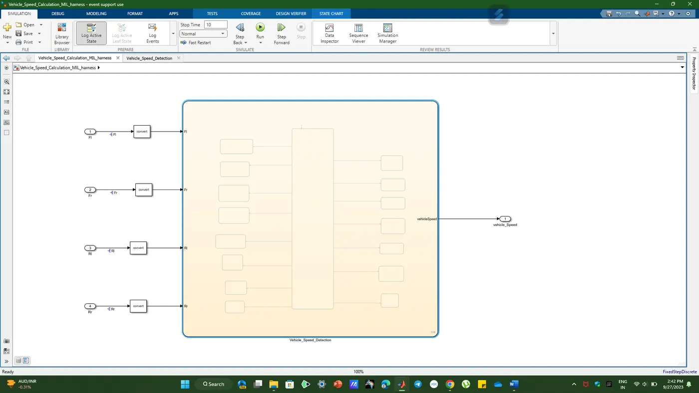
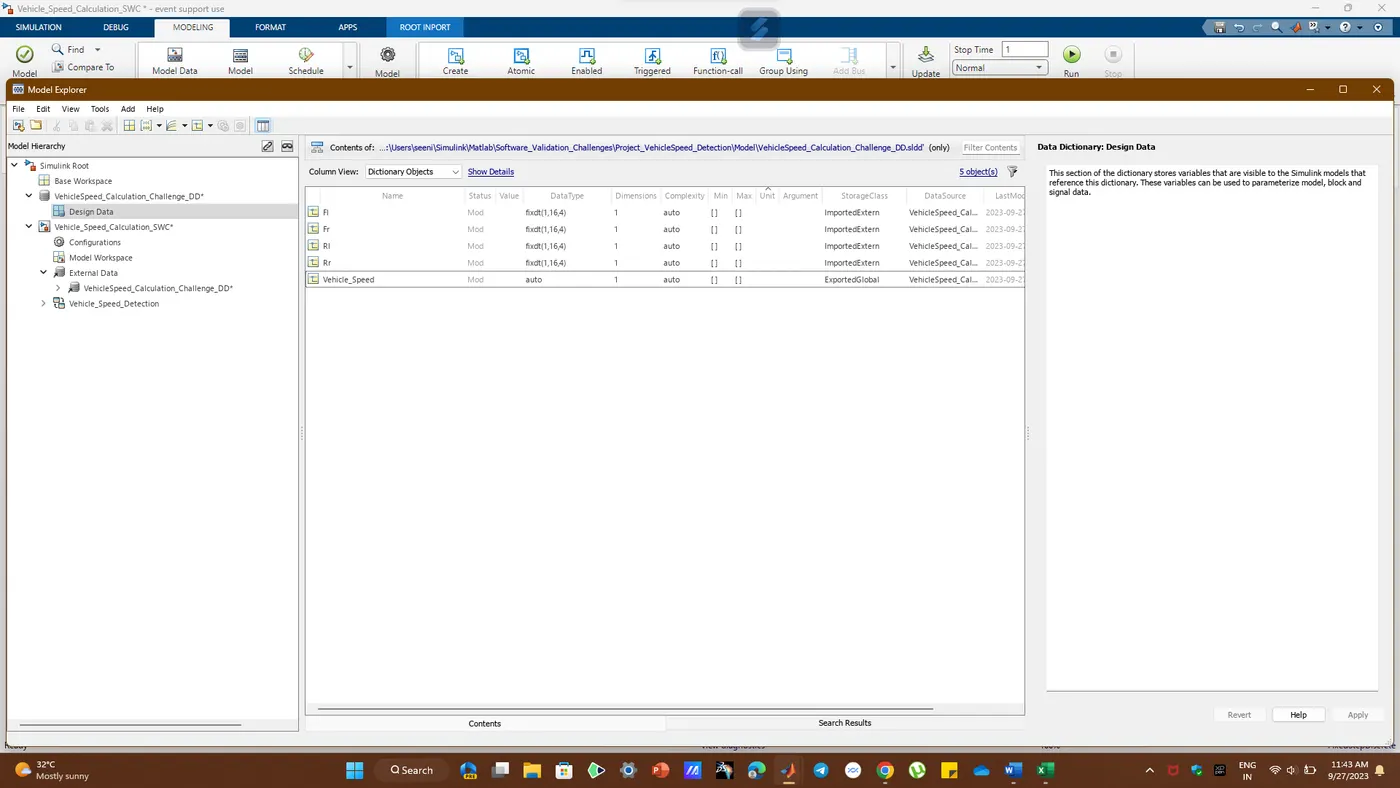
SLDD File Creation:
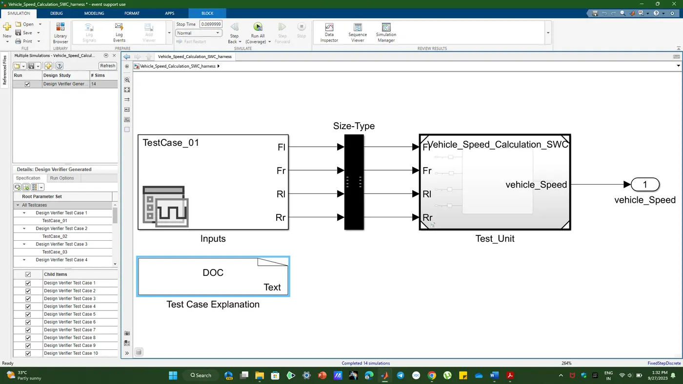
we are taking input from the 4 Wheeel Sensors and one Output Sensors the names are Fl (Front-Left),Fr(Front-Right),Rl(Rear - left),Rr(Rear - right) and the output is Vehicle Speed.
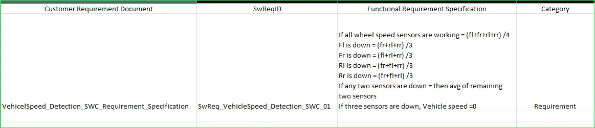
Requirement Tagging Report:
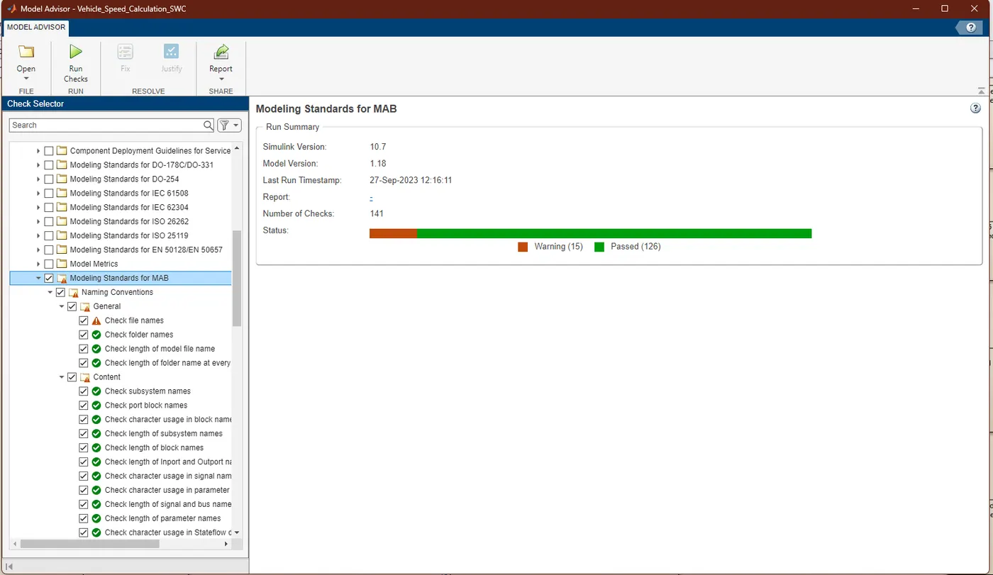
JMAAB- MAB Model Advisor Report:
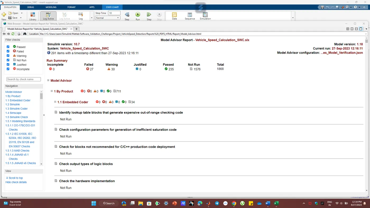
HTML Report:
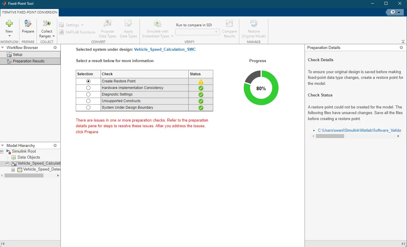
Fixed Tool Point:
It Converts Floating Values to Fixed Point Values
1. Toolchain Configuration: A fixed tool point defines the exact versions and configurations of all the software tools used in the model-based development process. This includes modeling tools (e.g., Simulink), simulation engines, code generation tools, verification and validation tools, and any other software components involved in the development lifecycle.
2. Stability: Once a fixed tool point is established, it remains unchanged throughout a specific phase of a project or for a particular application. It provides stability by preventing unexpected tool updates or modifications that could introduce compatibility issues or affect the reliability of simulation results.
3. Documentation: A fixed tool point is well-documented, specifying the versions and settings of each tool in the toolchain. This documentation is crucial for reproducibility, regulatory compliance, and ensuring that all team members use the same tool configuration.
4. Validation: The fixed tool point is validated to ensure that it meets the project's requirements and quality standards. This may involve testing the toolchain to verify that it produces accurate simulation results and complies with industry standards or safety regulations.
5. Change Control: Any changes to the toolchain or its configuration must be carefully controlled and documented. Changes should undergo a formal review and approval process to prevent unintended consequences.
6. Version Control: Version control systems, such as Git, are often used to manage the configurations and settings of the fixed tool point. This allows for tracking changes, rolling back to previous configurations, and collaborating among team members.
7. Application-Specific: Fixed tool points are often tailored to the specific needs of a project or application. For example, in safety-critical industries like automotive or aerospace, the fixed tool point may be customized to meet industry standards like ISO 26262 or DO-178C.
8. Reproducibility: Using a fixed tool point ensures that simulations and code generation processes are reproducible. This is essential for verifying and validating complex systems and complying with regulatory requirements.
9. Consistency: Consistency in the toolchain helps maintain the integrity of the development process and facilitates collaboration among team members, especially in large-scale projects.
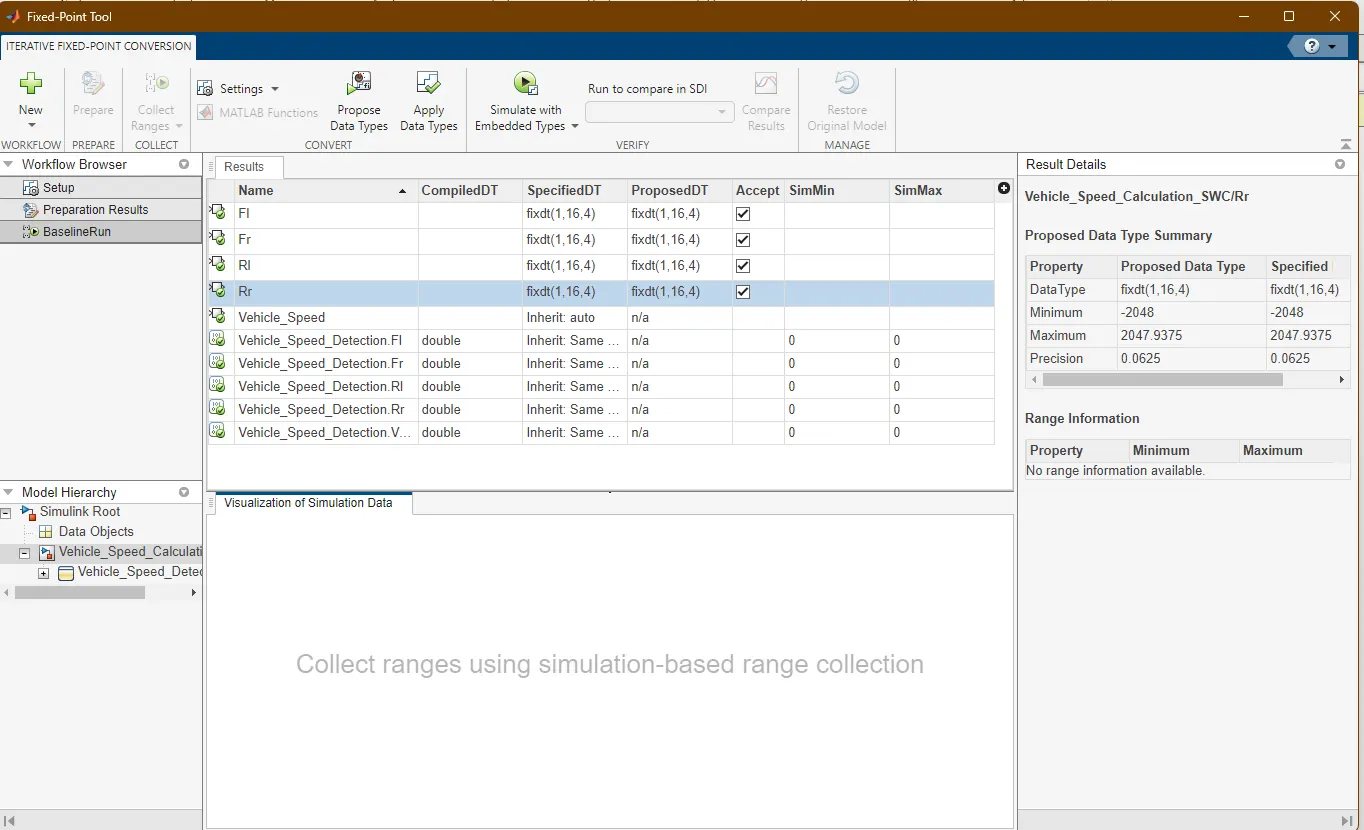
Proposed Data Types and Applied the Selected Data types:
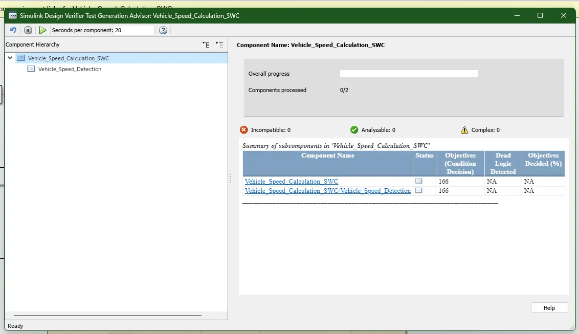
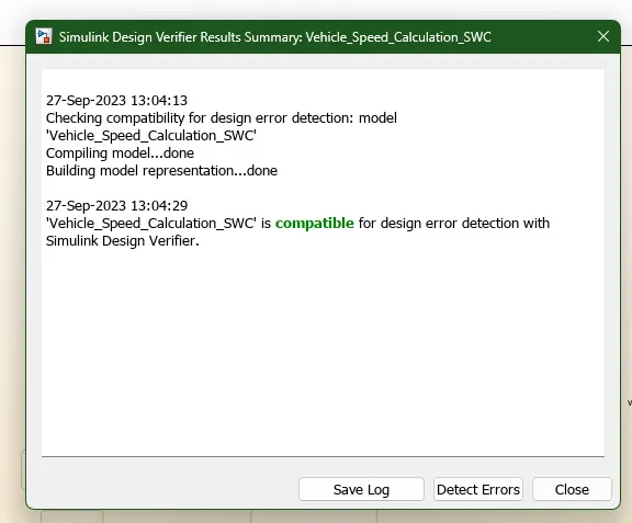
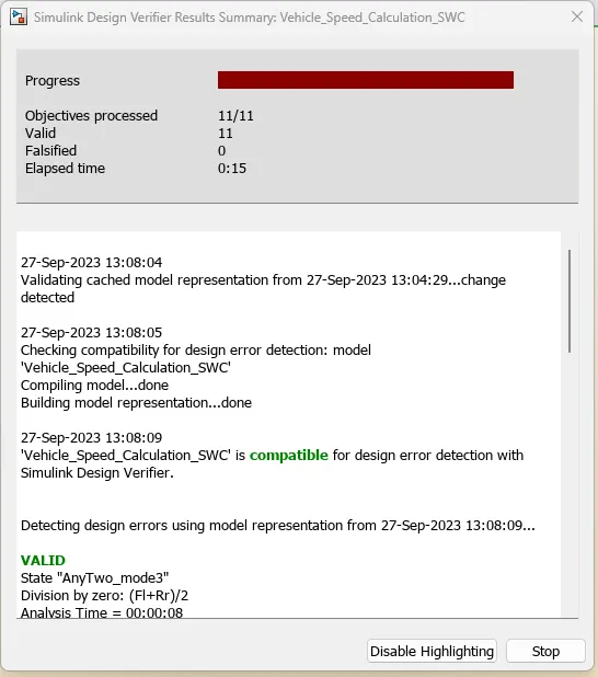
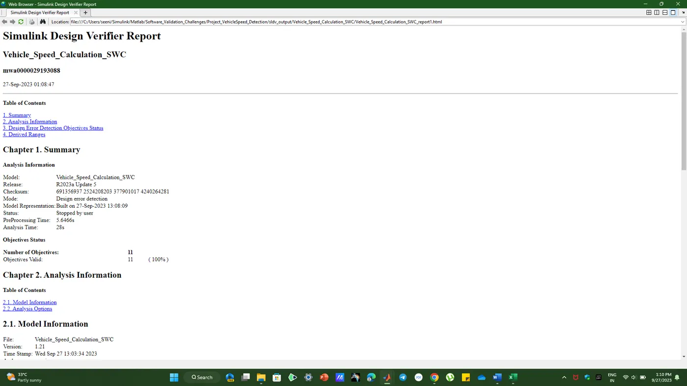
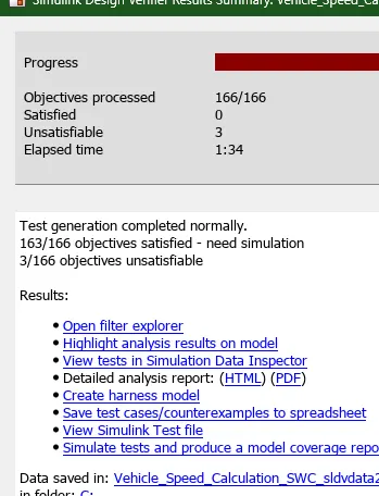
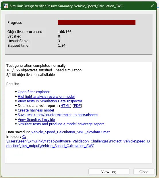
SlDV Design Error Detection and Test Generation:
SLDV HArness Model:
Model in Loop and Software In loop Testing:
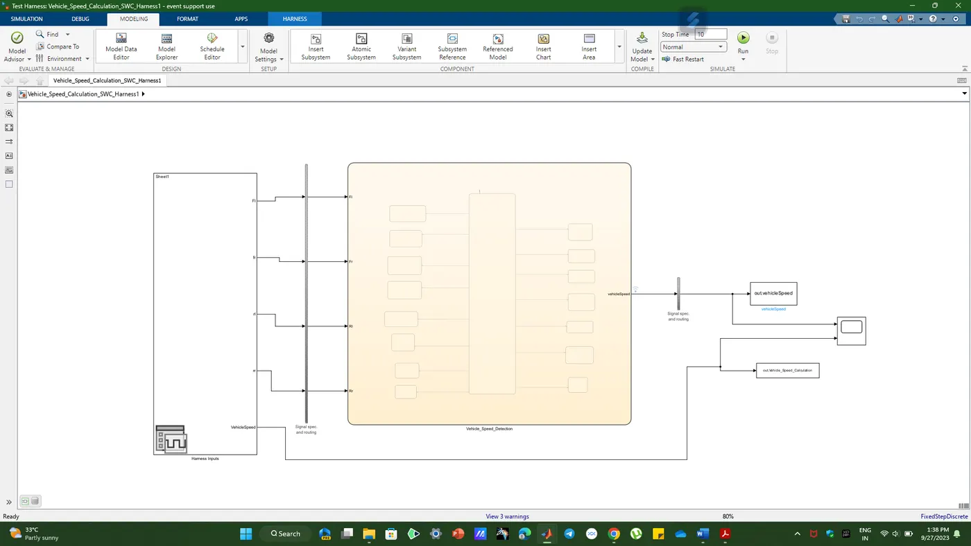
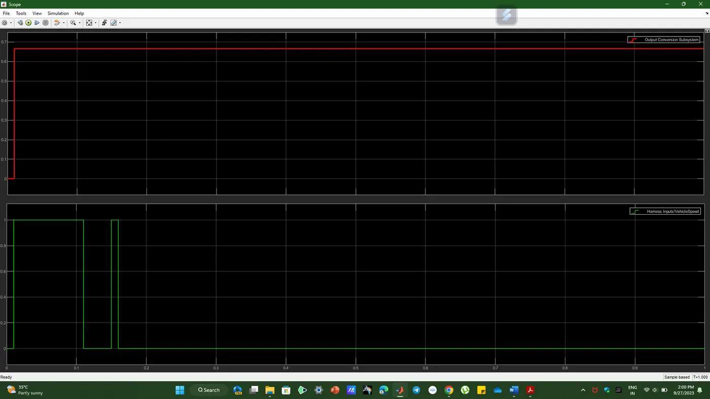
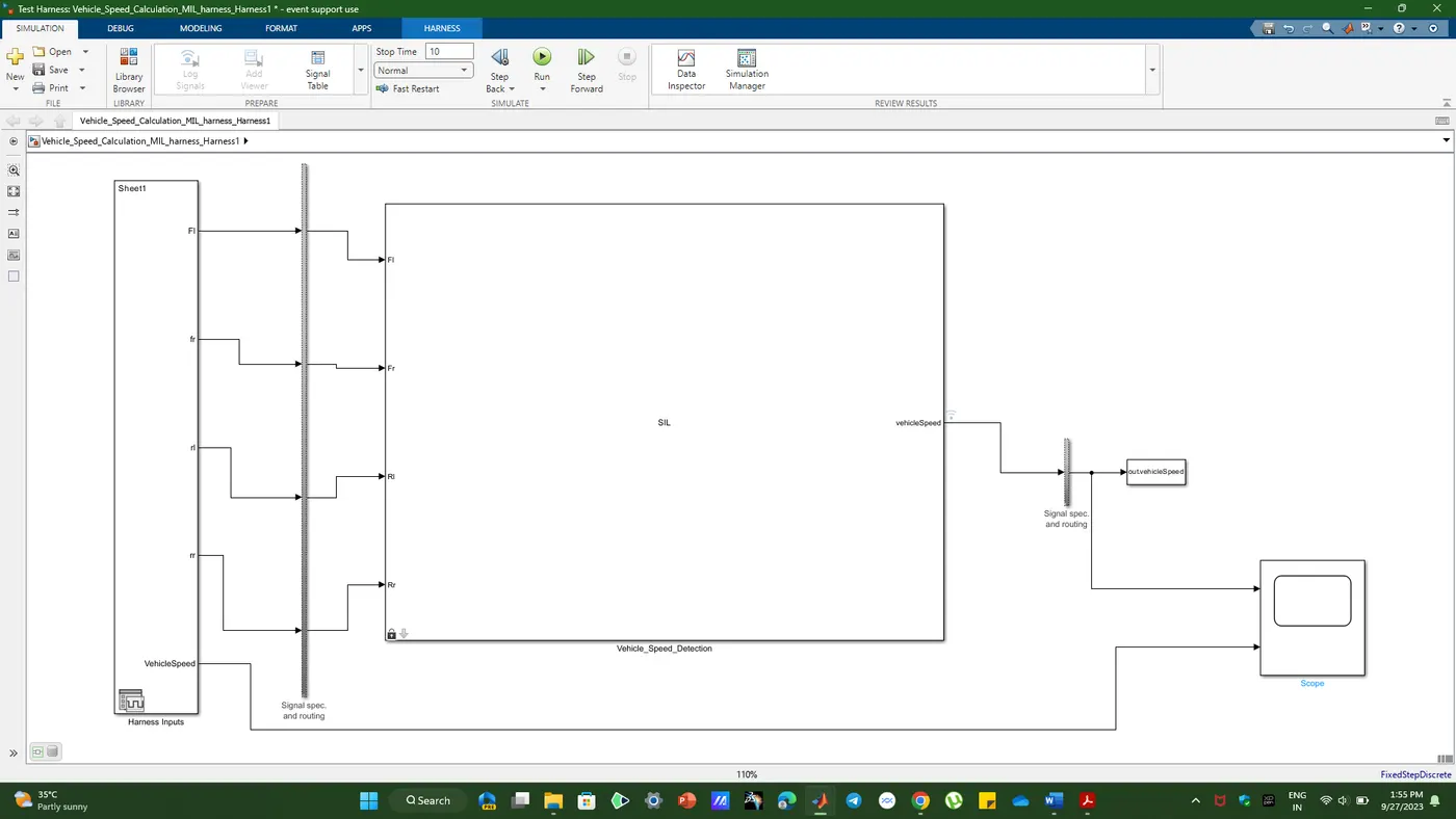
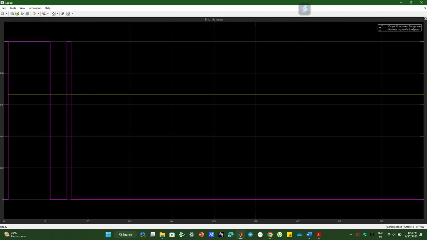
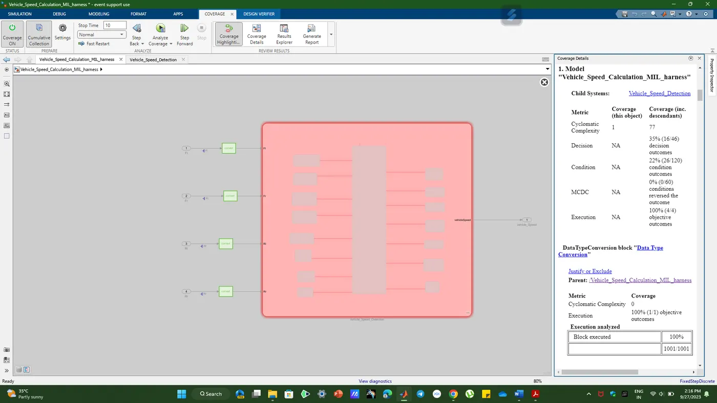
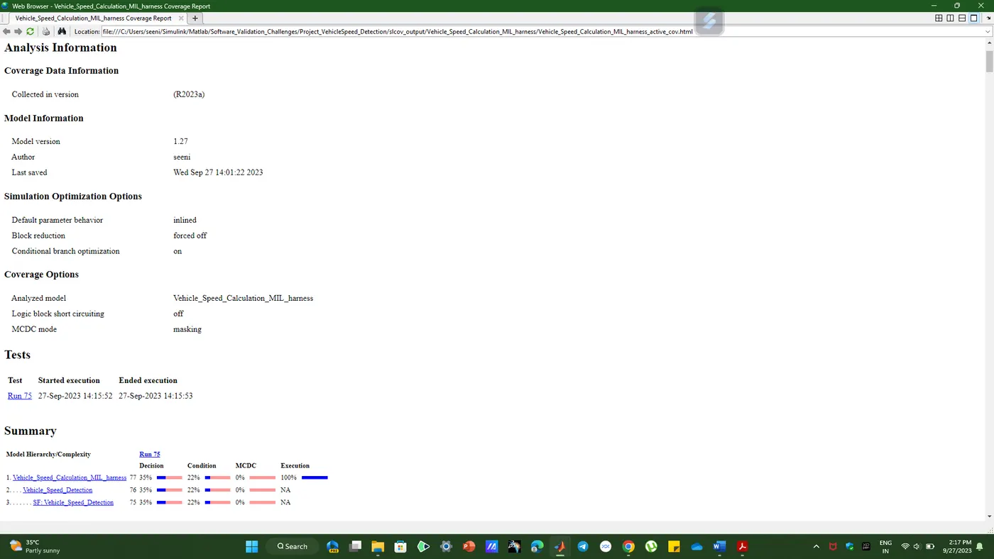
MIL and SIL Report:
Embedded Coder --> C-code:
/*
 * Event Support License -- for demonstration use and event support.  Not
 * for government, research, commercial, or other organizational use.
 *
 * File: Vehicle_Speed_Calculation_MIL_harness.c
 *
 * Code generated for Simulink model 'Vehicle_Speed_Calculation_MIL_harness'.
 *
 * Model version                  : 1.26
 * Simulink Coder version         : 9.9 (R2023a) 19-Nov-2022
 * C/C++ source code generated on : Wed Sep 27 13:46:53 2023
 *
 * Target selection: ert.tlc
 * Embedded hardware selection: Intel->x86-64 (Windows64)
 * Code generation objectives: Unspecified
 * Validation result: Not run
 */

#include "Vehicle_Speed_Calculation_MIL_harness.h"
#include "rtwtypes.h"
#include "Vehicle_Speed_Calculation_MIL_harness_private.h"

/* Named constants for Chart: '/Vehicle_Speed_Detection' */
#define Vehicle_S_IN_AllSensorsWorking1 ((uint8_T)1U)
#define Vehicle_Speed_C_IN_AnyTwo_mode1 ((uint8_T)2U)
#define Vehicle_Speed_C_IN_AnyTwo_mode2 ((uint8_T)3U)
#define Vehicle_Speed_C_IN_AnyTwo_mode3 ((uint8_T)4U)
#define Vehicle_Speed_C_IN_AnyTwo_mode4 ((uint8_T)5U)
#define Vehicle_Speed_C_IN_AnyTwo_mode5 ((uint8_T)6U)
#define Vehicle_Speed_C_IN_AnyTwo_mode6 ((uint8_T)7U)
#define Vehicle_Speed_C_IN_Default_Mode ((uint8_T)12U)
#define Vehicle_Speed_C_IN_FlSensorDown ((uint8_T)13U)
#define Vehicle_Speed_C_IN_FrSensorDown ((uint8_T)14U)
#define Vehicle_Speed_C_IN_RlSensorDown ((uint8_T)15U)
#define Vehicle_Speed_C_IN_RrSensorDown ((uint8_T)16U)
#define Vehicle_Speed_IN_Anythree_mode1 ((uint8_T)8U)
#define Vehicle_Speed_IN_Anythree_mode2 ((uint8_T)9U)
#define Vehicle_Speed_IN_Anythree_mode3 ((uint8_T)10U)
#define Vehicle_Speed_IN_Anythree_mode4 ((uint8_T)11U)

/* Block states (default storage) */
DW_Vehicle_Speed_Calculation__T Vehicle_Speed_Calculation_MI_DW;

/* External outputs (root outports fed by signals with default storage) */
ExtY_Vehicle_Speed_Calculatio_T Vehicle_Speed_Calculation_MIL_Y;

/* Real-time model */
static RT_MODEL_Vehicle_Speed_Calcul_T Vehicle_Speed_Calculation_MI_M_;
RT_MODEL_Vehicle_Speed_Calcul_T *const Vehicle_Speed_Calculation_MI_M =
  &Vehicle_Speed_Calculation_MI_M_;

/* Model step function */
void Vehicle_Speed_Calculation_MIL_harness_step(void)
{
  real_T tmp;
  real_T tmp_0;
  real_T tmp_1;
  real_T tmp_2;
  boolean_T tmp_3;
  boolean_T tmp_4;
  boolean_T tmp_5;
  boolean_T tmp_6;
  boolean_T tmp_7;
  boolean_T tmp_8;

  /* Chart: '/Vehicle_Speed_Detection' incorporates:
   *  DataTypeConversion: '/Data Type Conversion'
   *  DataTypeConversion: '/Data Type Conversion1'
   *  DataTypeConversion: '/Data Type Conversion2'
   *  DataTypeConversion: '/Data Type Conversion3'
   *
   * Block description for '/Vehicle_Speed_Detection':
   *  This Subsystem Calculates Average Vehicle From the Input sensors and
   *  Displays Vehicle Speed
   */
  if (Vehicle_Speed_Calculation_MI_DW.is_active_c3_Vehicle_Speed_Calc == 0U) {
    Vehicle_Speed_Calculation_MI_DW.is_active_c3_Vehicle_Speed_Calc = 1U;
    Vehicle_Speed_Calculation_MI_DW.is_c3_Vehicle_Speed_Calculation =
      Vehicle_Speed_C_IN_Default_Mode;

    /* Outport: '/vehicle_Speed' */
    Vehicle_Speed_Calculation_MIL_Y.vehicle_Speed = 0.0;
  } else {
    switch (Vehicle_Speed_Calculation_MI_DW.is_c3_Vehicle_Speed_Calculation) {
     case Vehicle_S_IN_AllSensorsWorking1:
     case Vehicle_Speed_C_IN_AnyTwo_mode1:
     case Vehicle_Speed_C_IN_AnyTwo_mode2:
has popup
Polyspace Bug Finder's Process and Report/output of multi-spatial analysis
Steps to create a Polyspace report:
- First, open Polyspace with a new project and click Start New Project.
- The Project Properties dialog box will open, specify the name of the project you saved in MATLAB, select the location to save it, and then click Next or use the default location.
- Next, request the Projrct source and click in your browser to select the folder where the .c file will be generated. You can then add include folders as needed, and once complete, the Polyspace environment will open.
- In the configuration settings option called Targets and Compilers, select the language of the source code as C and change the desired processor to X86_64.
- In the Enable MISRA C:2004 Checks for Coding Standards and Code Metrics section, select the option to calculate code metrics.
- Then go to debugger analysis and select default.
- Go to reports and activate the option to generate the report and output the PDF format or the required file.
- Finally, save the polyspace and run the Bug Finder.
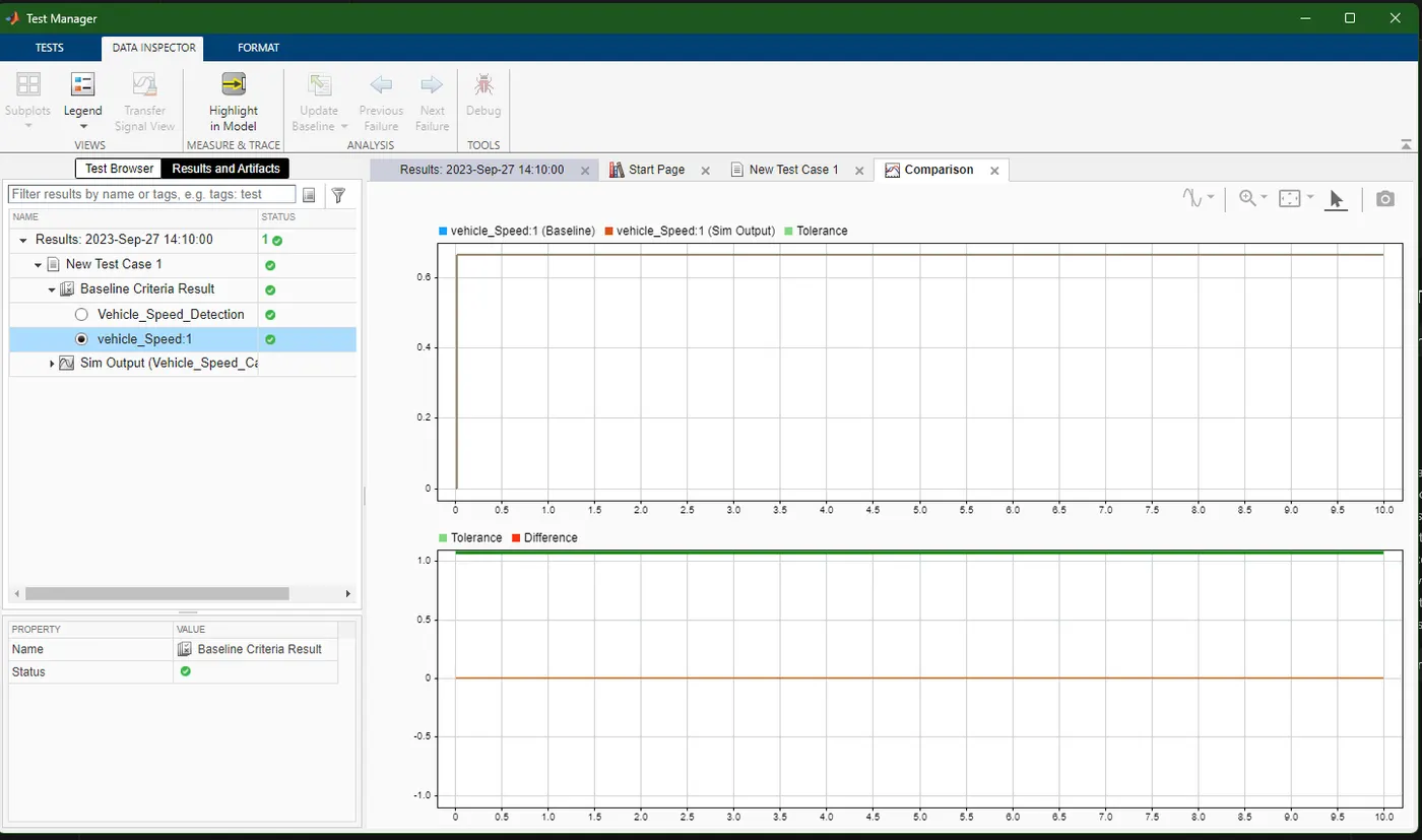
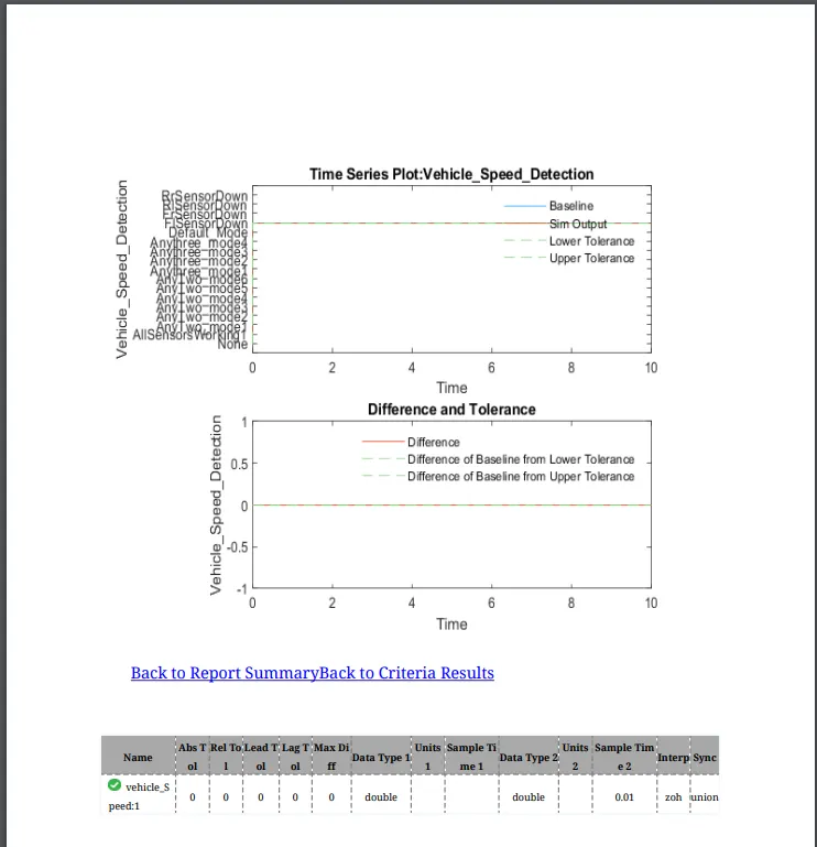
Test manager and Baseline Testing:
Result:
The expected output is obtained for the simulink model for vehicle speed calculation unit inside the ABS system.
Embedded Coder:
C-code From Embedded Coder:
/*
 * Event Support License -- for demonstration use and event support.  Not
 * for government, research, commercial, or other organizational use.
 *
 * File: Wiperspeed_ABS_Challenge_MIL_Harness.c
 *
 * Code generated for Simulink model 'Wiperspeed_ABS_Challenge_MIL_Harness'.
 *
 * Model version                  : 1.14
 * Simulink Coder version         : 9.9 (R2023a) 19-Nov-2022
 * C/C++ source code generated on : Sun Sep 24 15:31:14 2023
 *
 * Target selection: ert.tlc
 * Embedded hardware selection: Intel->x86-64 (Windows64)
 * Code generation objectives: Unspecified
 * Validation result: Not run
 */

#include "Wiperspeed_ABS_Challenge_MIL_Harness.h"
#include "rtwtypes.h"
#include "Wiperspeed_ABS_Challenge_MIL_Harness_private.h"

/* Exported data definition */

/* Definition for custom storage class: Localizable */
int16_T High_Rain;                     /* '/Switch' */
uint16_T Low_Rain;                     /* '/Switch' */
int16_T Medium_Rain;                   /* '/Switch' */
int16_T No_Rain;                       /* '/Switch' */

/* Real-time model */
static RT_MODEL_Wiperspeed_ABS_Chall_T Wiperspeed_ABS_Challenge_MIL_M_;
RT_MODEL_Wiperspeed_ABS_Chall_T *const Wiperspeed_ABS_Challenge_MIL_M =
  &Wiperspeed_ABS_Challenge_MIL_M_;

/* Model step function */
void Wiperspeed_ABS_Challenge_MIL_Harness_step(void)
{
  /* (no output/update code required) */
}

/* Model initialize function */
void Wiperspeed_ABS_Challenge_MIL_Harness_initialize(void)
{
  /* ConstCode for Constant: '/Rain_Density' */
  Rain_Density = 51200U;

  /* ConstCode for Atomic SubSystem: '/ABS_Calculation' */
  /* ConstCode for Switch: '/Switch' */
  if (Wiperspeed_ABS_Challenge_ConstB.Relational_Operator) {
    /* ConstCode for Switch: '/Switch' incorporates:
     *  Constant: '/Constant2'
     */
    High_Rain = 8000;
  } else {
    /* ConstCode for Switch: '/Switch' incorporates:
     *  Constant: '/Constant1'
     */
    High_Rain = 0;
  }

  /* End of ConstCode for Switch: '/Switch' */

  /* ConstCode for Switch: '/Switch' */
  if (Wiperspeed_ABS_Challenge_ConstB.AND) {
    /* ConstCode for Switch: '/Switch' incorporates:
     *  Constant: '/Constant2'
     */
    Low_Rain = 51200U;
  } else {
    /* ConstCode for Switch: '/Switch' incorporates:
     *  Constant: '/Constant3'
     */
    Low_Rain = 512U;
  }

  /* End of ConstCode for Switch: '/Switch' */

  /* ConstCode for Switch: '/Switch' */
  if (Wiperspeed_ABS_Challenge_ConstB.AND_a) {
    /* ConstCode for Switch: '/Switch' incorporates:
     *  Constant: '/Constant2'
     */
    Medium_Rain = 3200;
  } else {
    /* ConstCode for Switch: '/Switch' incorporates:
     *  Constant: '/Constant3'
     */
    Medium_Rain = 0;
  }

  /* End of ConstCode for Switch: '/Switch' */
  /* End of ConstCode for SubSystem: '/ABS_Calculation' */
}

/* Model terminate function */
void Wiperspeed_ABS_Challenge_MIL_Harness_terminate(void)
{
  /* (no terminate code required) */
}

/*
 * File trailer for generated code.
 *
 * [EOF]
 */
has popup