Project 1 - Wiper control system and Vehicle speed calculation for ABS using Wheel Speed sensor
-Develop the Simulink model based on the given descriptions for the below challenges and also create SLDD file and link the same to the model. Perform the complete V and V workflow for the obtained models.
 1).Wiper control system:
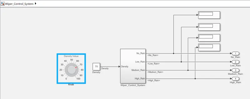
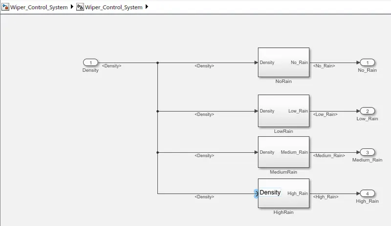
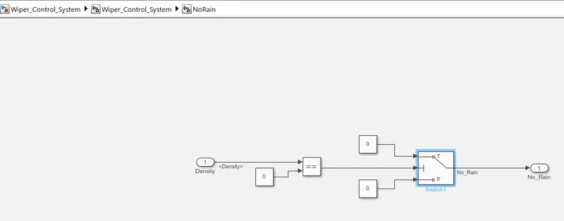
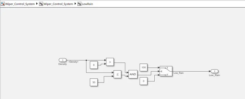
-Develop Simulink/state flow model for wiper control system based on the given conditions.
-Description of Challenge:
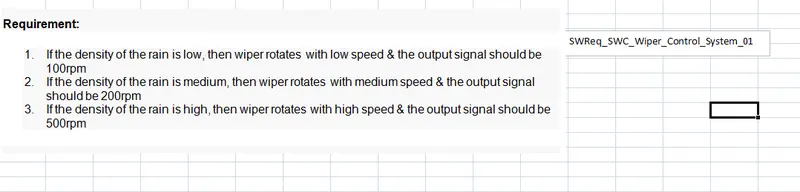
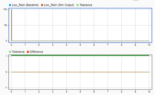
- If the density of the rain is low, then wiper rotates with low speed & the output signal should be 100rpm
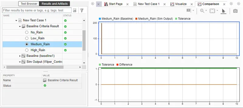
- If the density of the rain is medium, then wiper rotates with medium speed & the output signal should be 200rpm
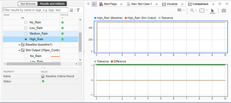
- If the density of the rain is high, then wiper rotates with high speed & the output signal should be 500rpm.
-1)Simulink Model File:
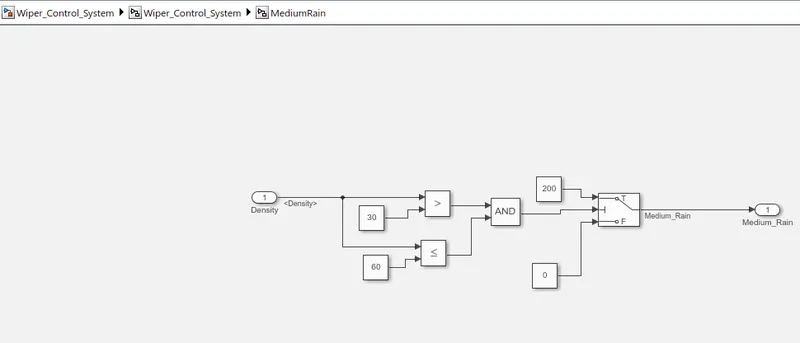
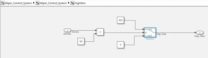
2)SLDD File:
-Create the SLDD File;
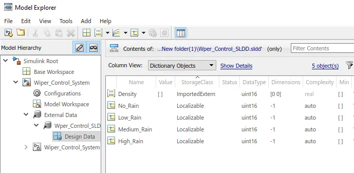
3)Requirement Tagging Report:
-Create the functional and SWReq file into the .xls File;
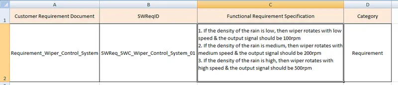
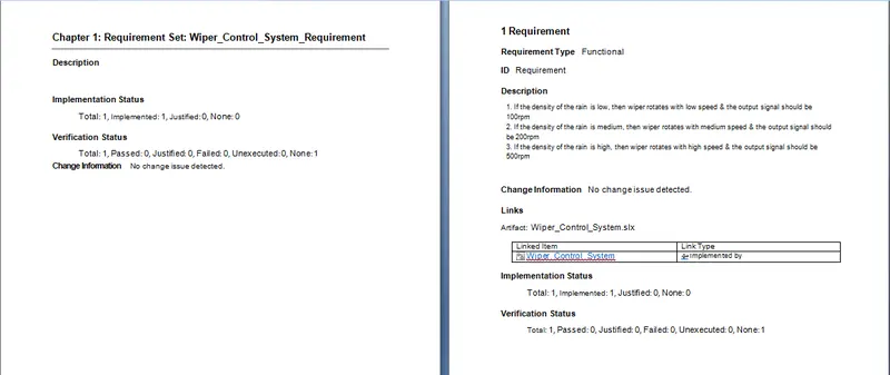
-Linking the Requirement to the model using Requirement Editor:
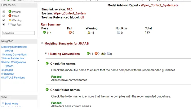
4)Model advisor-JMAAB Compliance Report:
-Open the Model into the Simulink editor tab and Click on 'model advisor'>>select'Modeling standards for JMAAB and click on 'Run selected check';
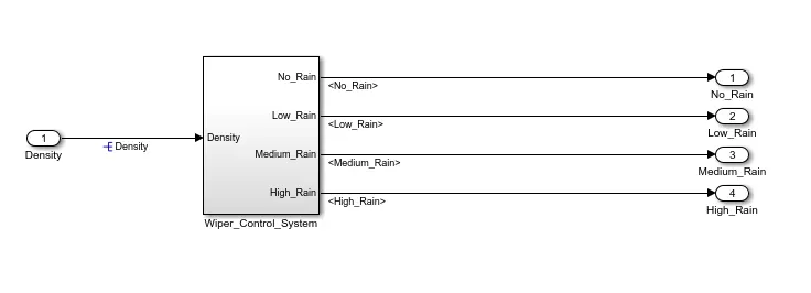
5)Fixed-point Tool:
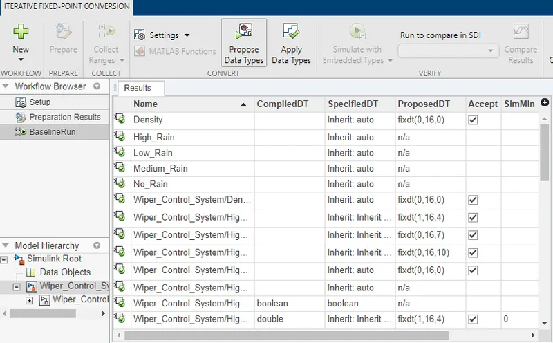
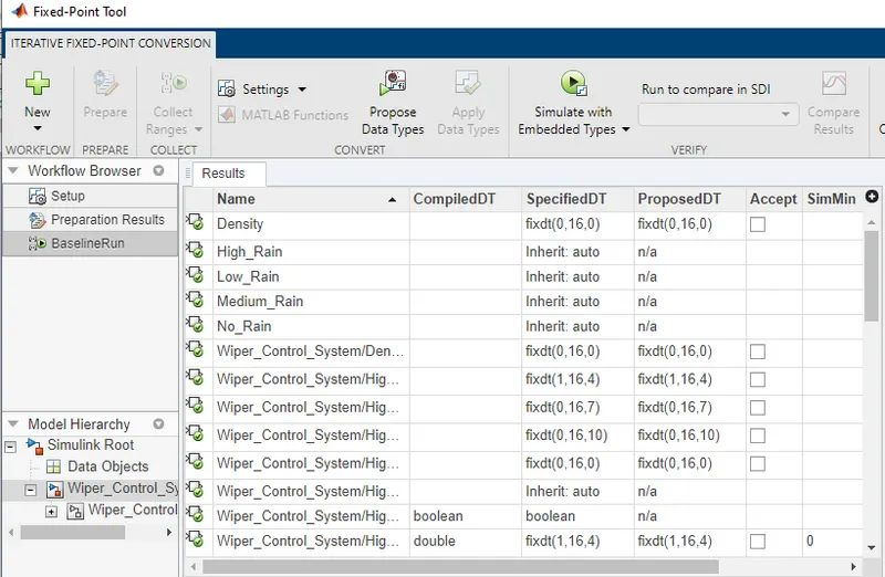
-Run the Model error free>>Click on 'Fixed-point Tool' app>>Click on 'New'>>Click on Iterative Fixed-point conversion;
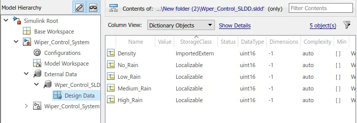
-SLDD Before applying Fixed-point Tool;
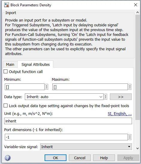
-Input signal Before Fixed-Point:
 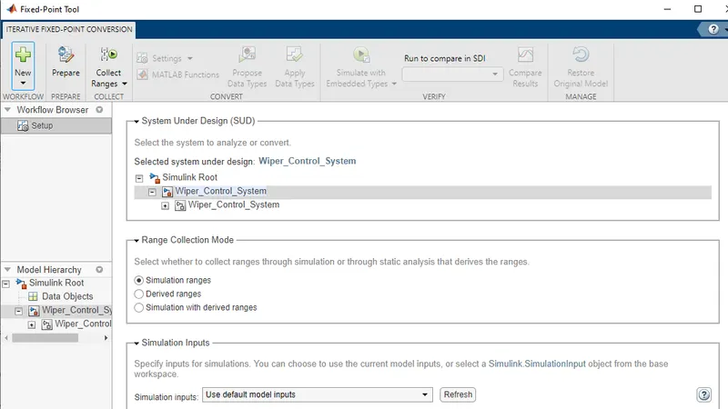
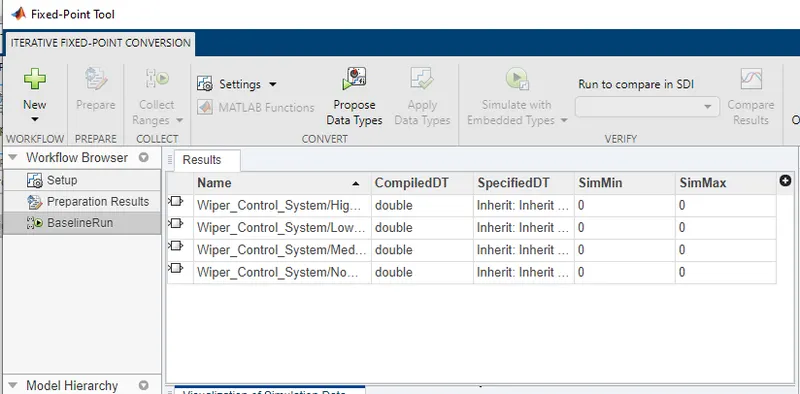
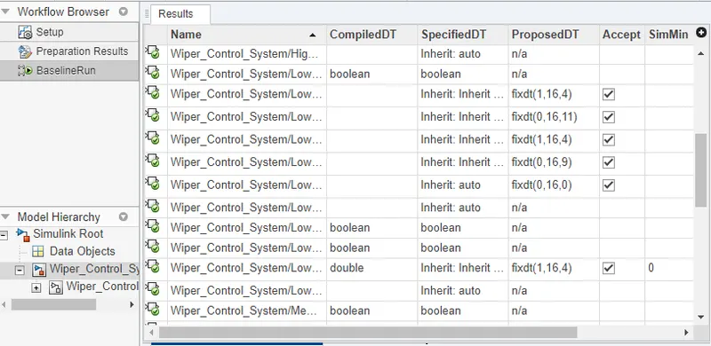
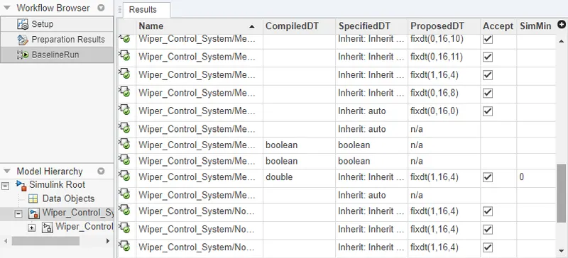
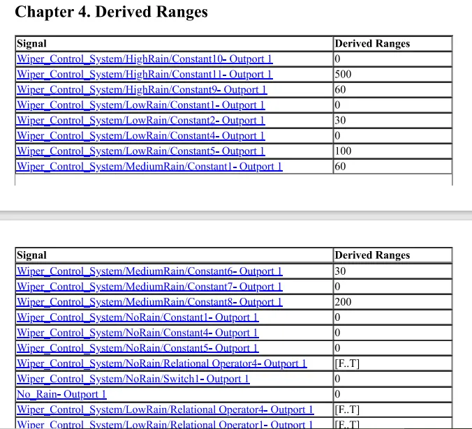
-Then click on 'Prepare' then click on 'collect Ranges'>>then Click on 'Propose Data Type>>click on 'Apply Data Type;

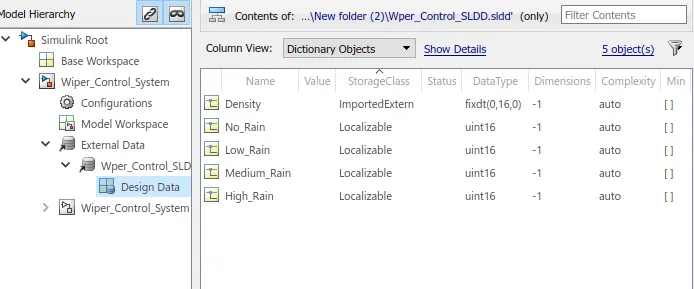
-SLDD After Fixed-point Tool Applying:
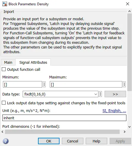
-Input Signal After Fixed-Point Tool:
SLDV Design Error Detection Report:
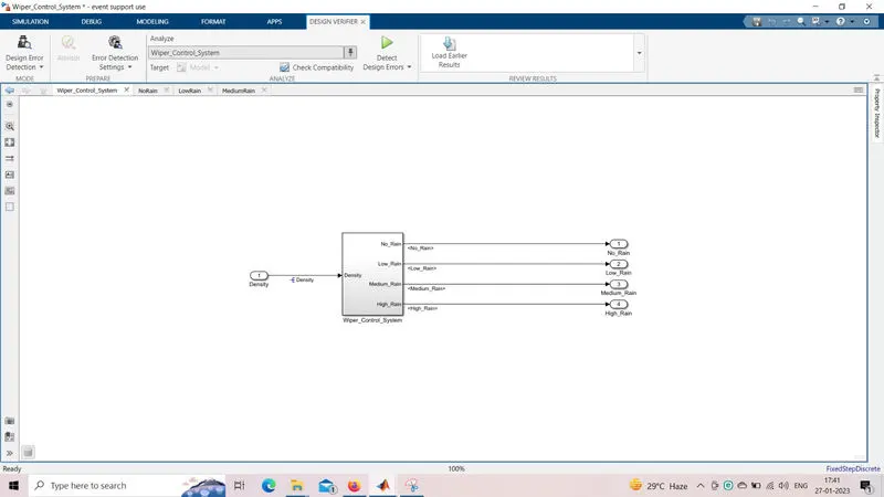
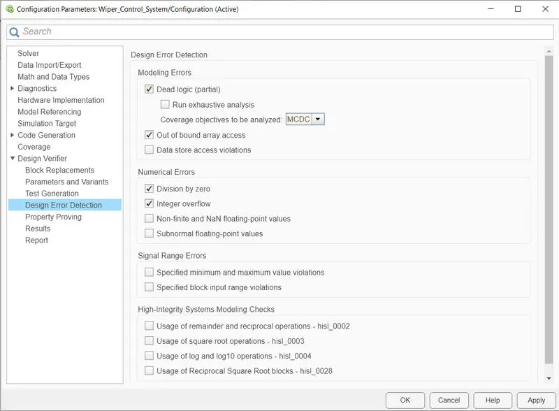
-Go to the model>>open the 'Design verifier' app>>Select 'design error Detection'>>'then Error detection setting'>>ckeack for 'compatibility'>>Click on 'Detect design Errors;
-Report:
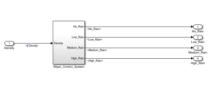
-MIL Model;
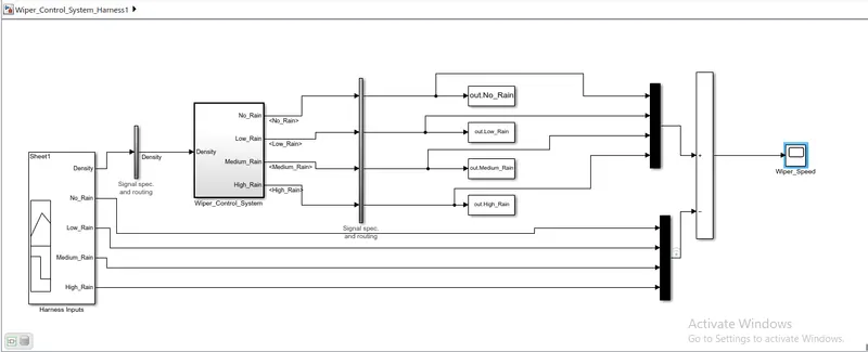
-Functional test cases;
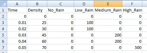
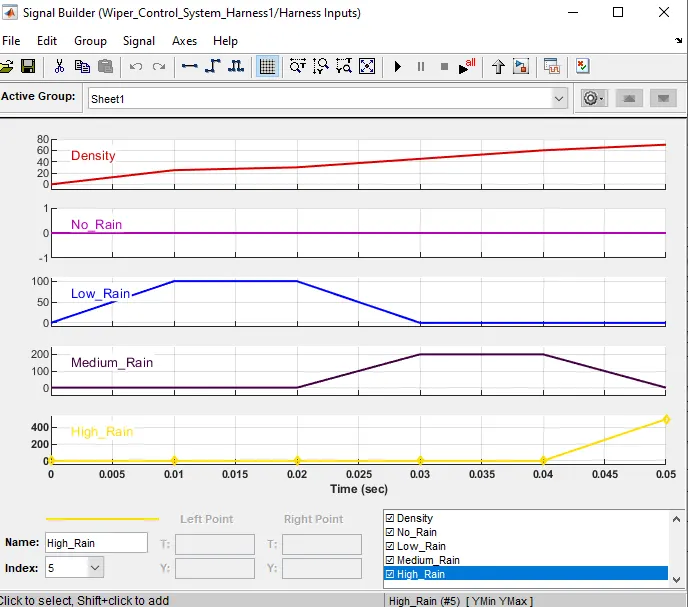
-Signal builder input signal;
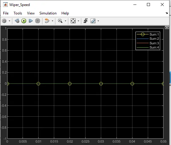
-MIL Output;
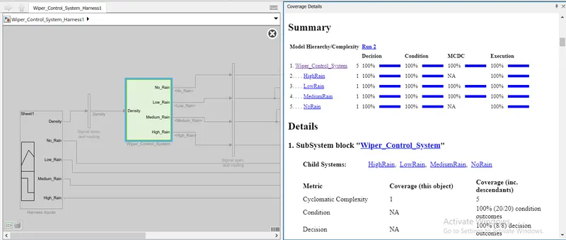
-MIL Coverage Reports;
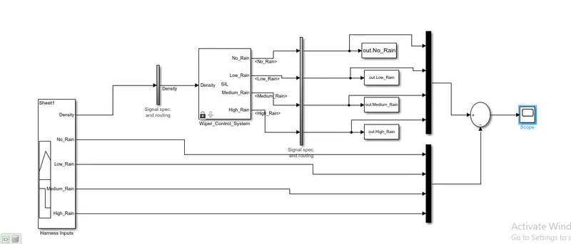
-SIL Model;
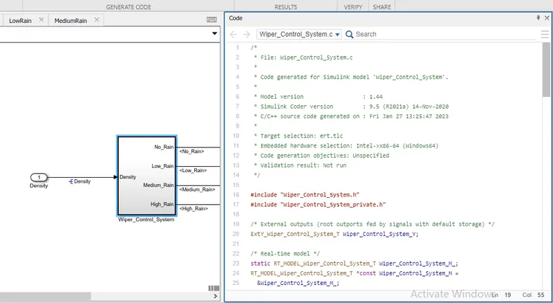
-Code Generation Report;
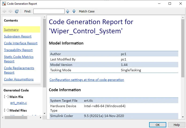
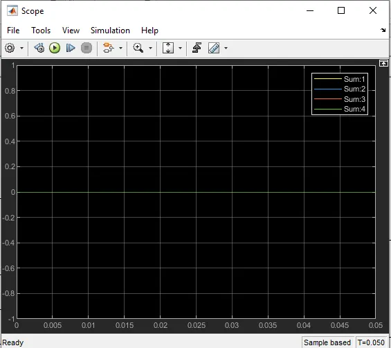
-SIL Output;
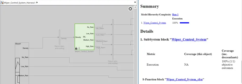
-SIL coverage Reports;
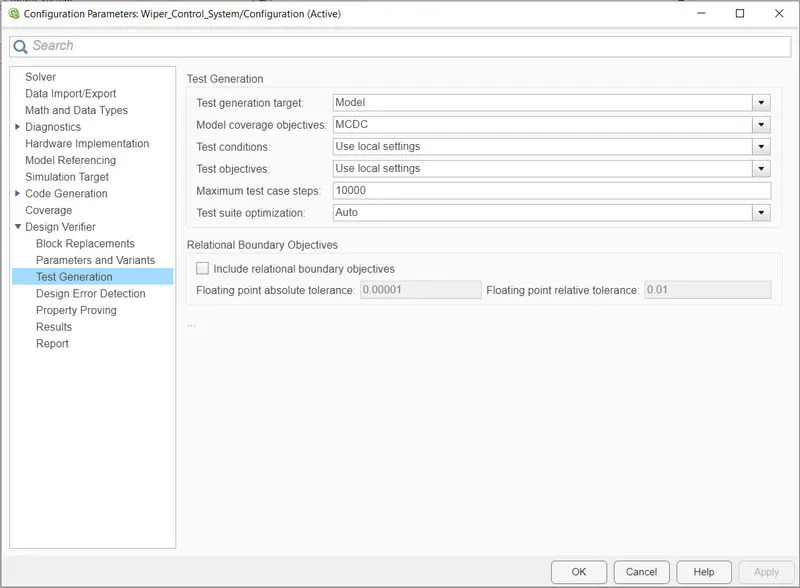
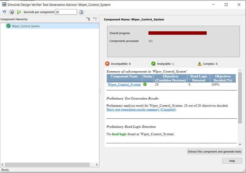
-Reports;
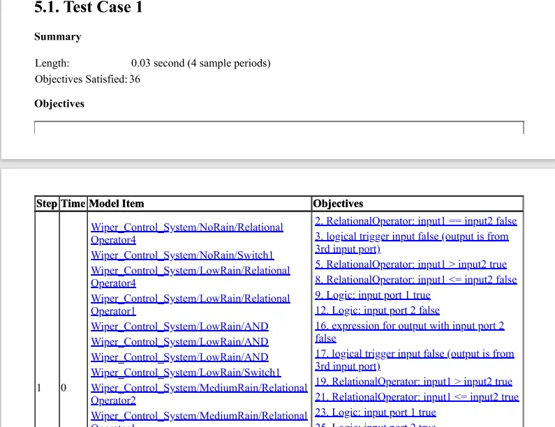
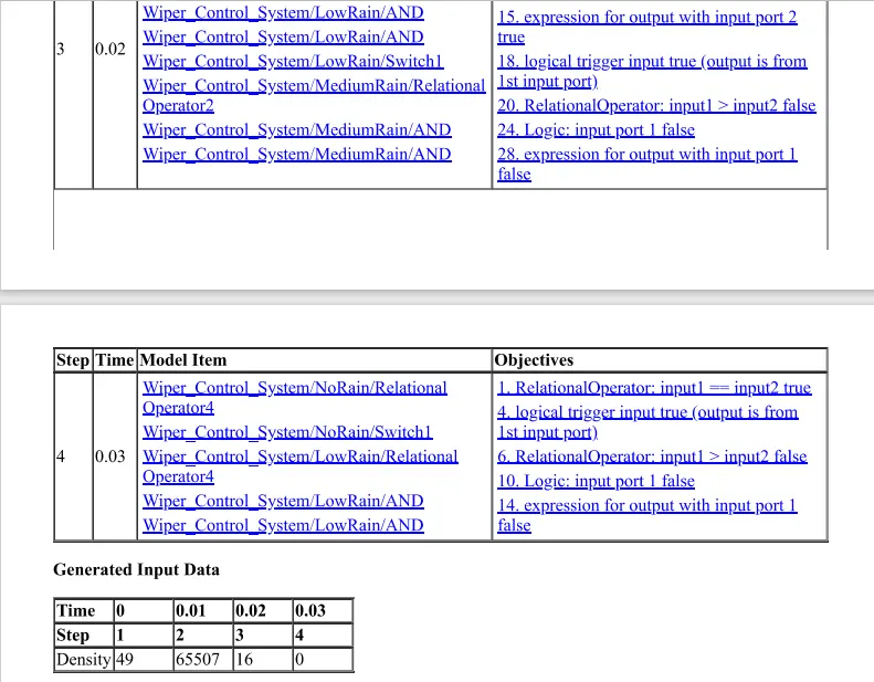
-Code Reports;
Wiper_Control_System.c
(22)
Highlighting: selected 11 blocks
1 / 27
/*

 * File: Wiper_Control_System.c

 *

 * Code generated for Simulink model 'Wiper_Control_System'.

 *

 * Model version                  : 1.44

 * Simulink Coder version         : 9.5 (R2021a) 14-Nov-2020

 * C/C++ source code generated on : Mon April 17 17:57:32 2023

 *

 * Target selection: ert.tlc

 * Embedded hardware selection: Intel->x86-64 (Windows64)

 * Code generation objectives: Unspecified

 * Validation result: Not run

 */


#include "Wiper_Control_System.h"

#include "Wiper_Control_System_private.h"


/* External outputs (root outports fed by signals with default storage) */

ExtY_Wiper_Control_System_T Wiper_Control_System_Y;


/* Real-time model */

static RT_MODEL_Wiper_Control_System_T Wiper_Control_System_M_;

RT_MODEL_Wiper_Control_System_T *const Wiper_Control_System_M =

  &Wiper_Control_System_M_;


/* Model step function */

void Wiper_Control_System_step(void)

{

  /* Outputs for Atomic SubSystem: '/Wiper_Control_System' */

  /* Outport: '/No_Rain' incorporates:

   *  Constant: '/Constant5'

   *  Switch: '/Switch1'

   */

  Wiper_Control_System_Y.No_Rain = 0;


  /* Switch: '/Switch1' incorporates:

   *  Inport: '/Density'

   *  Logic: '/AND'

   *  RelationalOperator: '/Relational Operator1'

   *  RelationalOperator: '/Relational Operator4'

   */

  if ((Density > 0) && (Density <= 30)) {

    /* Outport: '/Low_Rain' incorporates:

     *  Constant: '/Constant5'

     */

    Wiper_Control_System_Y.Low_Rain = 1600;

  } else {

    /* Outport: '/Low_Rain' incorporates:

     *  Constant: '/Constant4'

     */

    Wiper_Control_System_Y.Low_Rain = 0;

  }


  /* End of Switch: '/Switch1' */


  /* Switch: '/Switch2' incorporates:

   *  Inport: '/Density'

   *  Logic: '/AND'

   *  RelationalOperator: '/Relational Operator1'

   *  RelationalOperator: '/Relational Operator2'

   */

  if ((Density > 30) && (Density <= 60)) {

    /* Outport: '/Medium_Rain' incorporates:

     *  Constant: '/Constant8'

     */

    Wiper_Control_System_Y.Medium_Rain = 3200;

  } else {

    /* Outport: '/Medium_Rain' incorporates:
 10)Poly space Analysis Report/Outputs:
-For Bug Finder;
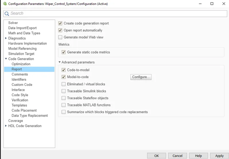
-Make code generation setting as below and built the model for code and generates the code using auto code generation;
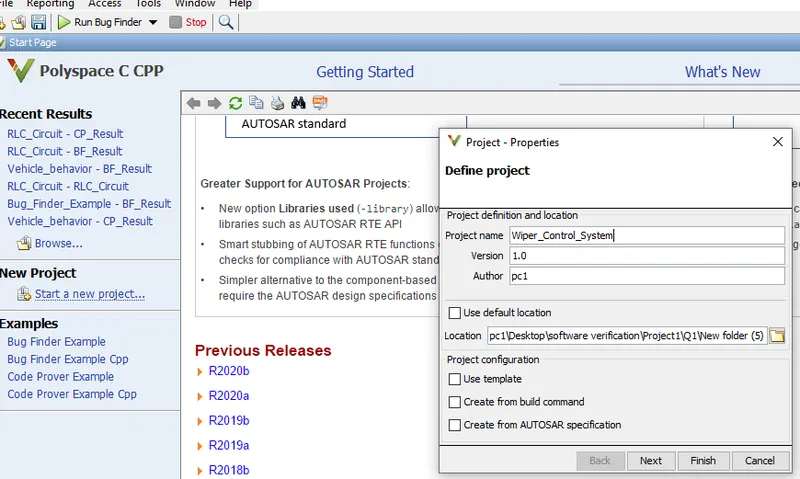
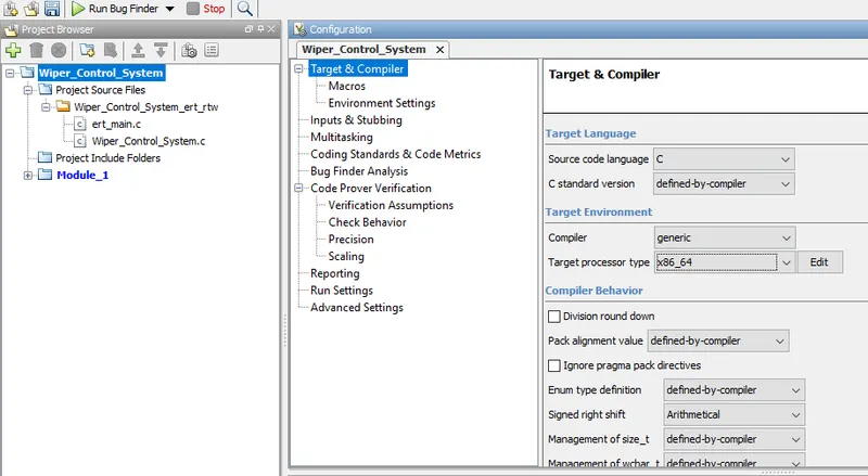
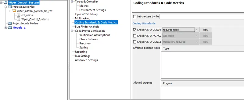
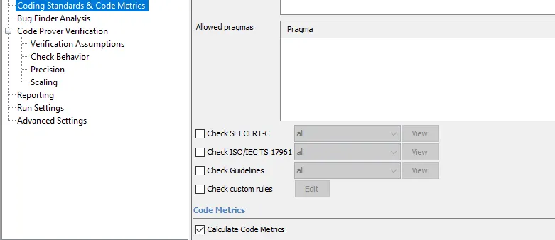
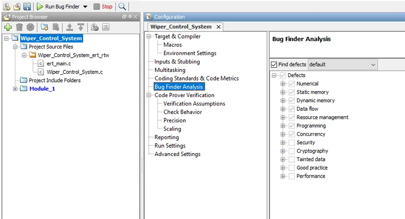
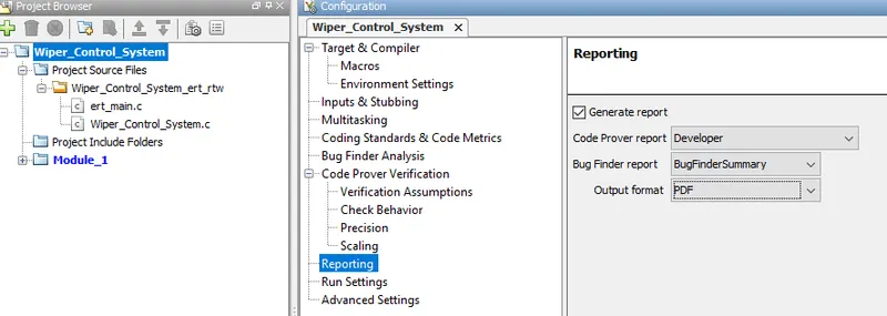
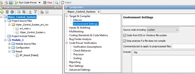
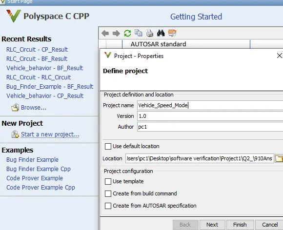
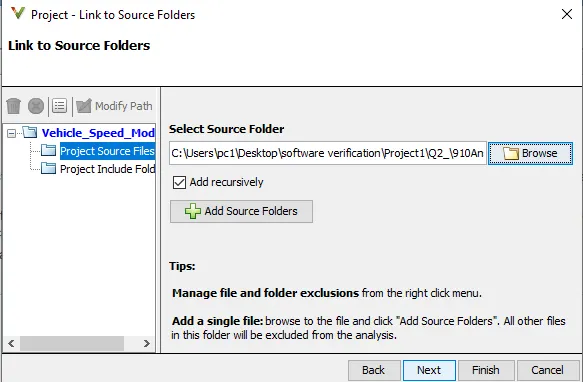
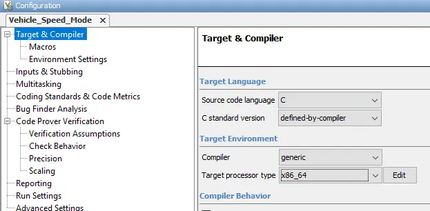
-Open the polyspace app Click on 'Start a New project Then link to a source file Select 'Bug Finder and make configuration setting as below and then save and Run Bug Finder;
Â
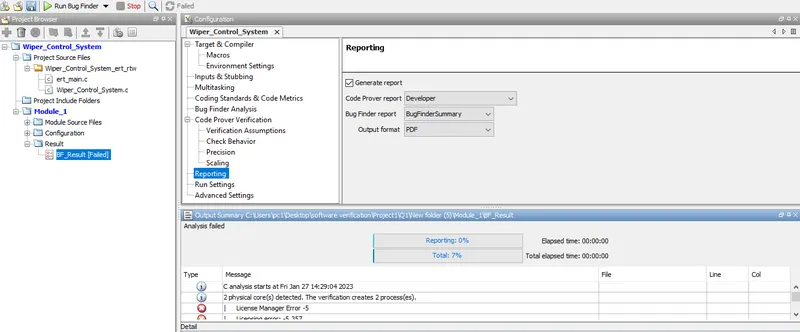
-Result:
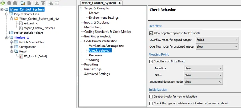
-For Code Prover;
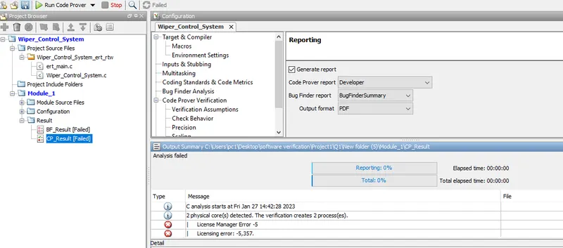
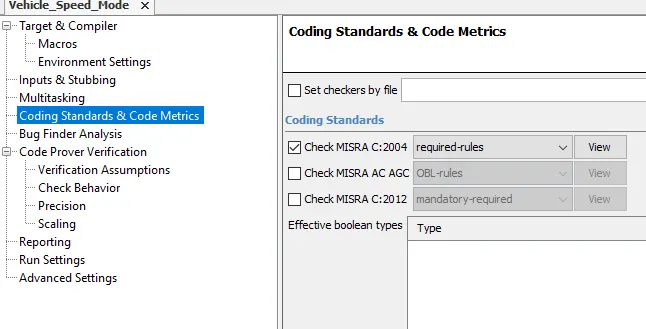
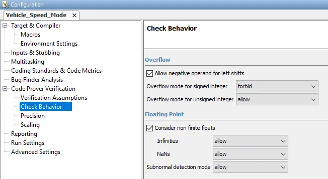
-Keeping above setting as same and select 'Code prover' and mk following configuration setting then save and Run the code prover;
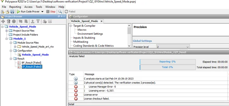
-Result:
Test Manager Reports-Baseline and Back_to_Back Testing:
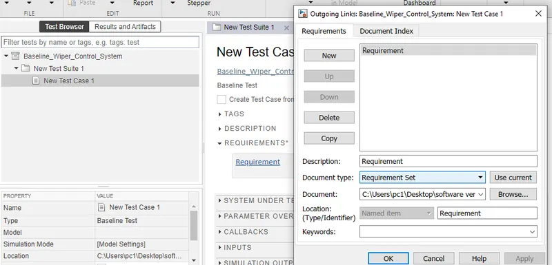
-Go to the Requirement;
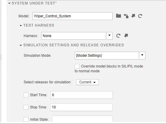
-Click on 'System under test';
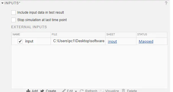
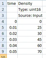
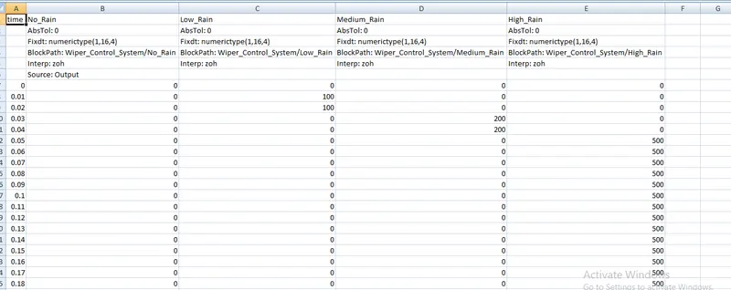
-Click on 'Input';
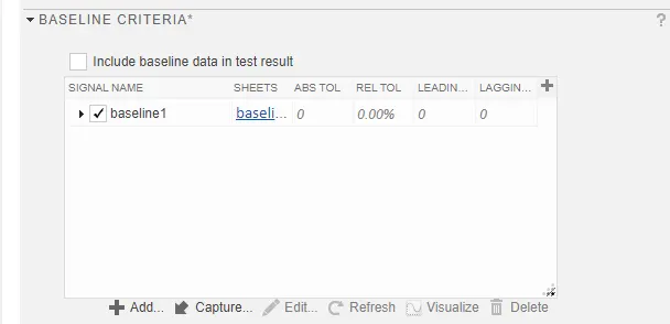
-Click on 'Baseline Criteria';
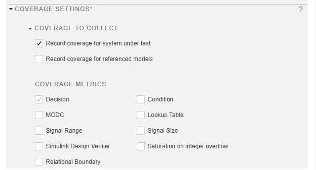
-Click on 'Coverage setting';
-Then save and Run the Test;
-Results:
-Baseline criteria reults;
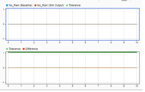
-Baseline output;
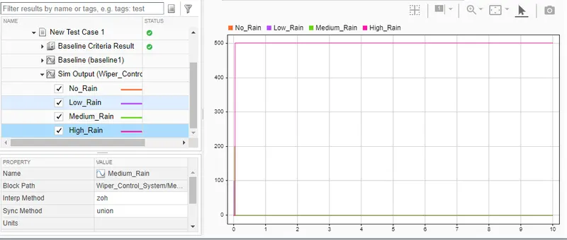
-Baseline test Result Reports;
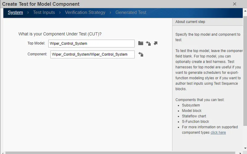
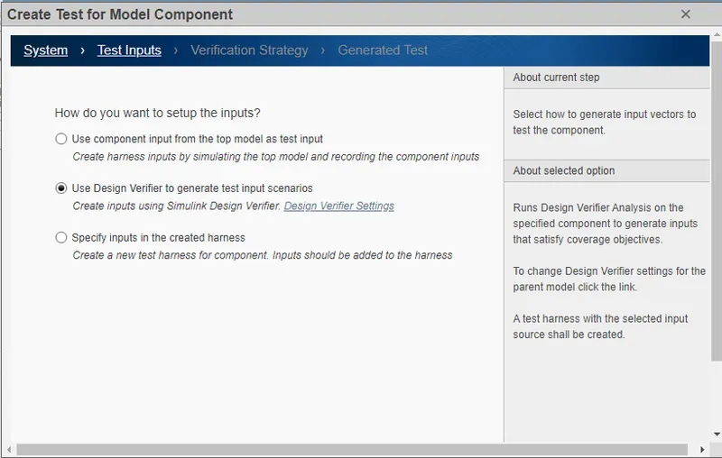
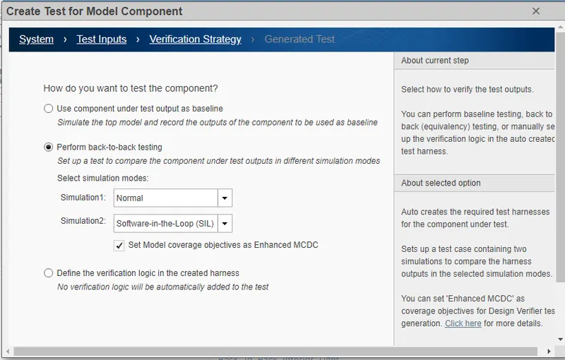
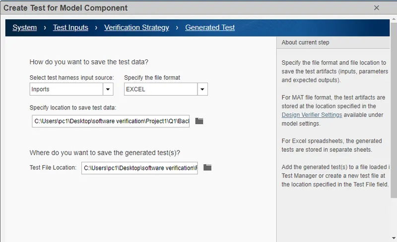
-For Back-to-Bach Testing;
-SLDV Reports;
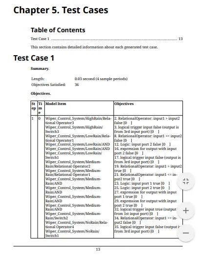
-Generated MIL And SIL model;
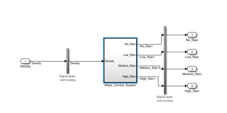
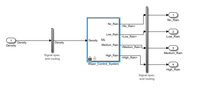
-Then Go to Requirements;
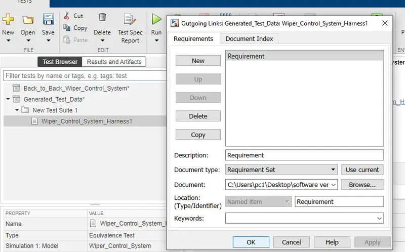
-Click on Coverage setting;
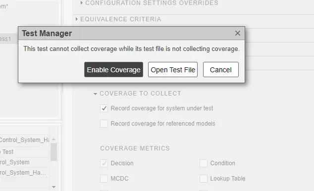
-Then Save and Run;
-Results
-Equivalence criteria Results
------------------------------------------------------------------------------------------------------
2).Vehicle speed calculation for ABS using Wheel Speed sensor.
-Develop Simulink/state flow model for the vehicle speed calculation unit inside the ABS system for the below conditions.
Description of Challenge:
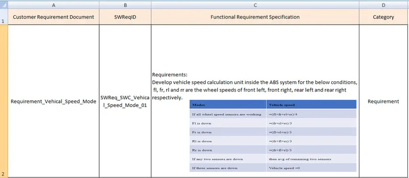
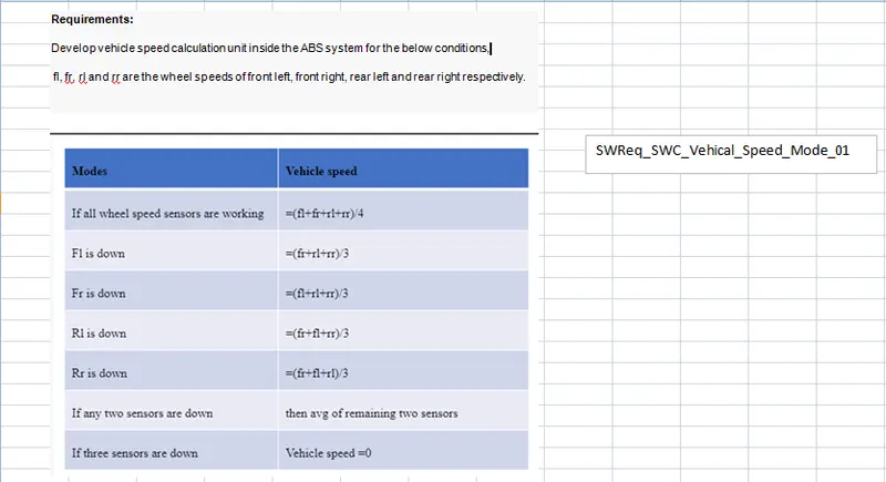
fl, fr, rl and rr are the wheel speeds of front left, front right, rear left and rear right respectively.
-1)Simulink Model File:
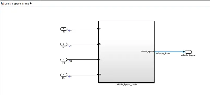
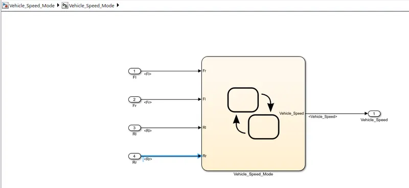
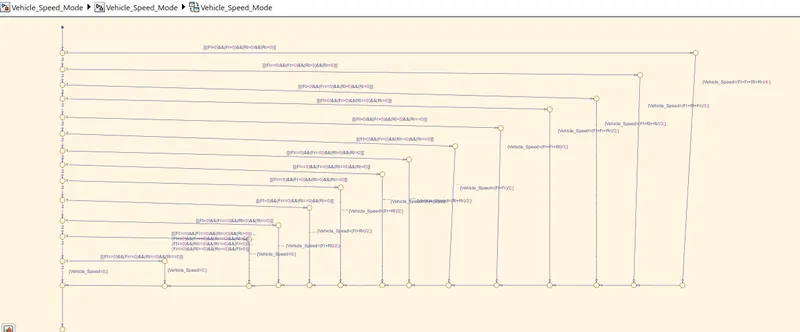
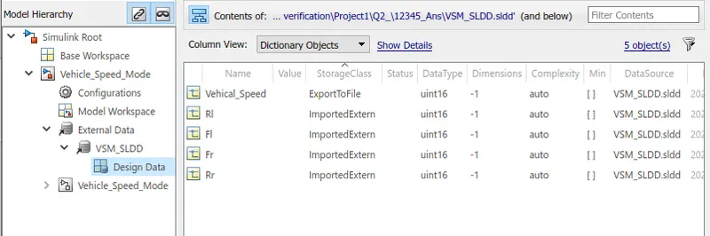
SLDD File:
-Create the SLDD File;
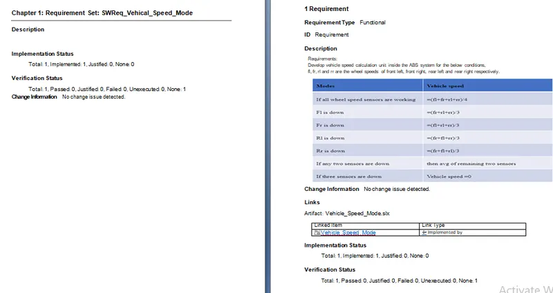
3)Requirement Tagging Report:
-Create the functional and SWReq file into the .xls File;
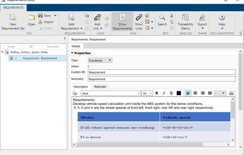
-Linking the Requirement to the model using Requirement Editor:
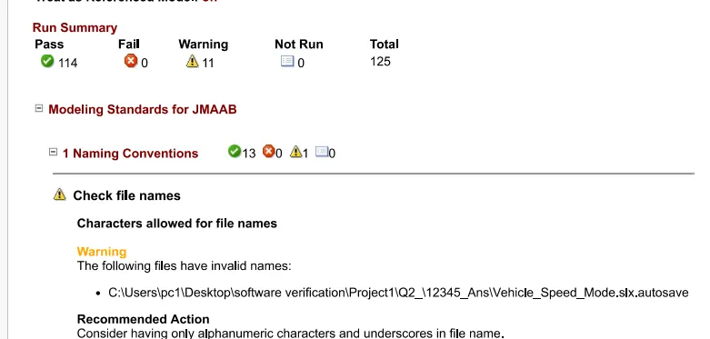
4)Model advisor-JMAAB Compliance Report:
-Open the Model into the Simulink editor tab and Click on 'model advisor'>>select'Modeling standards for JMAAB and click on 'Run selected check';
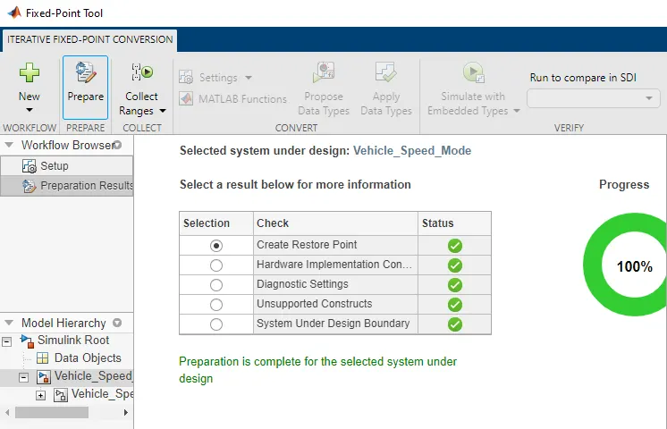
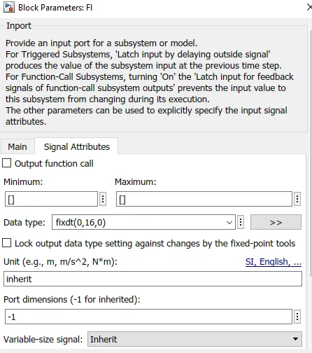
-Run the Model error free>>Click on 'Fixed-point Tool' app>>Click on 'New'>>Click on Iterative Fixed-point conversion;
-SLDD Before applying Fixed-point Tool;
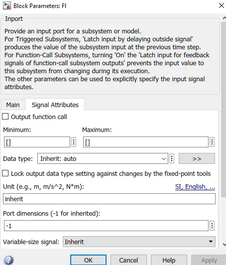
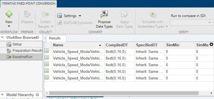
-Input signal Before Fixed-Point:
 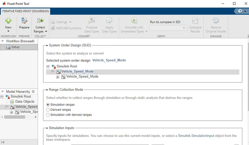
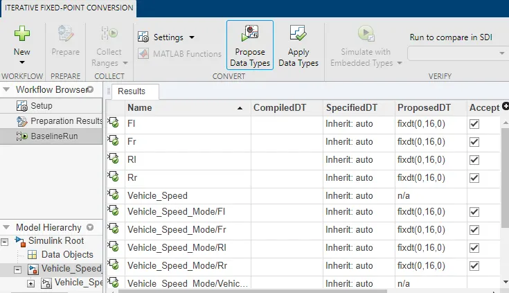
-Then click on 'Prepare' then click on 'collect Ranges'>>then Click on 'Propose Data Type>>click on 'Apply Data Type;
Â
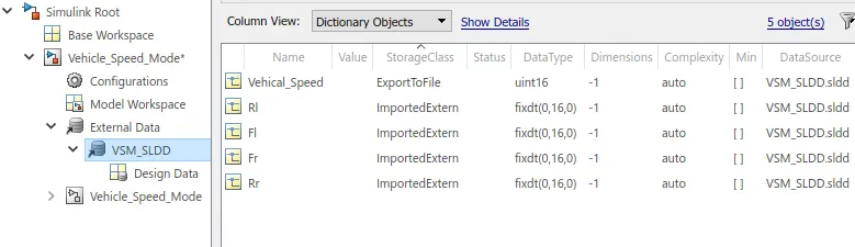
-SLDD After Fixed-point Tool Applying:
-Input Signal After Fixed-Point Tool:
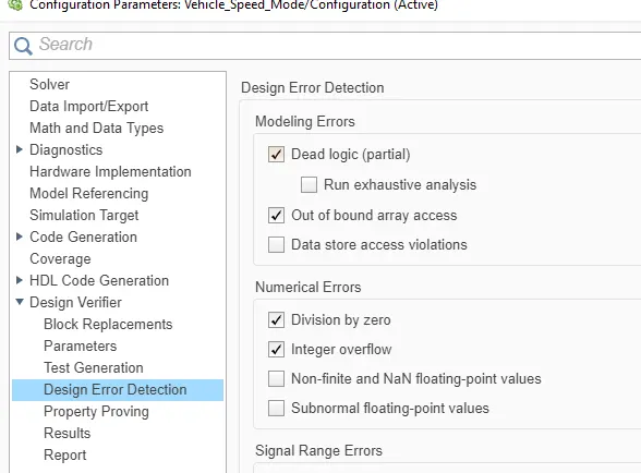
-Go to the model>>open the 'Design verifier' app>>Select 'design error Detection'>>'then Error detection setting'>>ckeack for 'compatibility'>>Click on 'Detect design Errors;
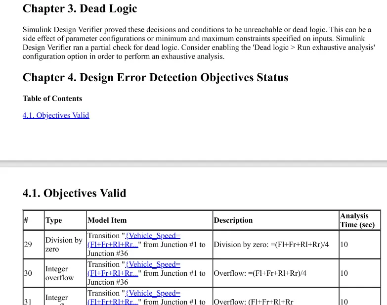
-Report:
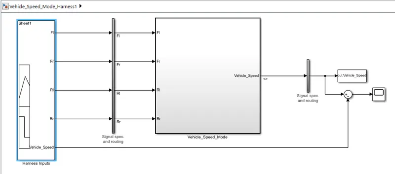
-Simulink Model;
-MIL Model;
-Functional test cases;
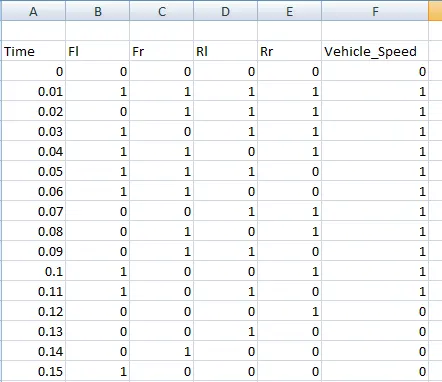
-Signal builder input signal;
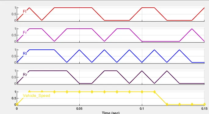
-MIL Output;
-MIL Coverage Reports;
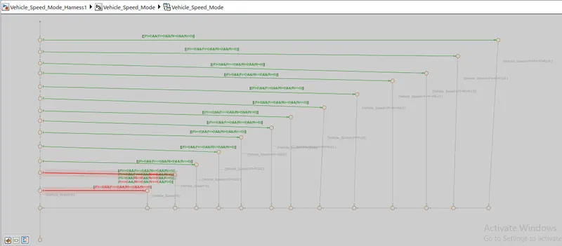
-SIL Model;
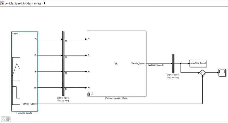
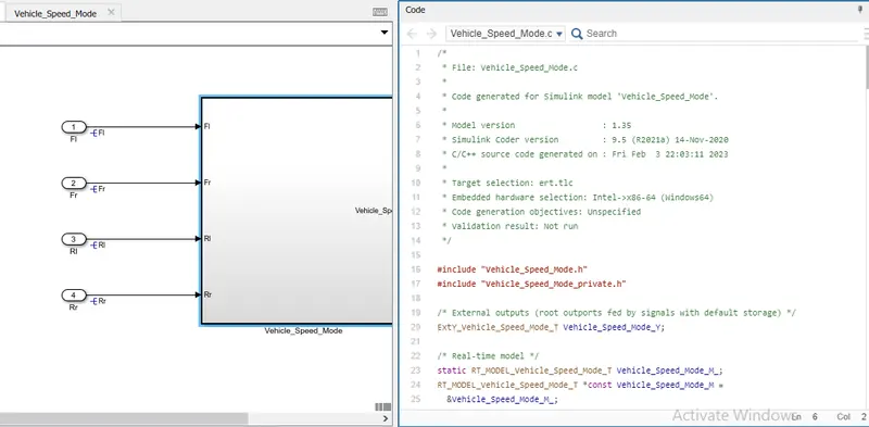
-Code Generation Report;
-SIL Output;
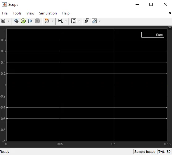
-SIL coverage Reports;
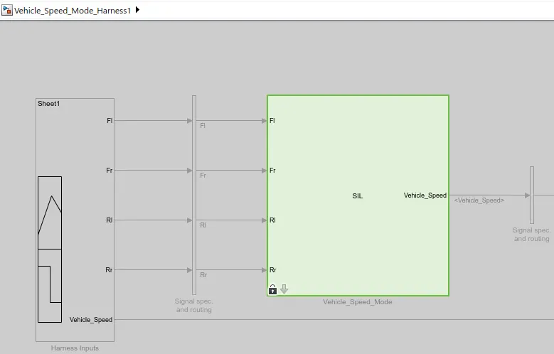
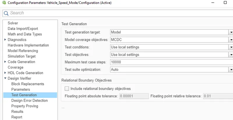
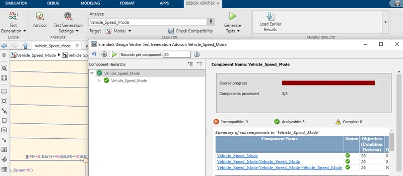
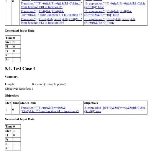
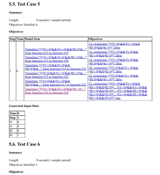
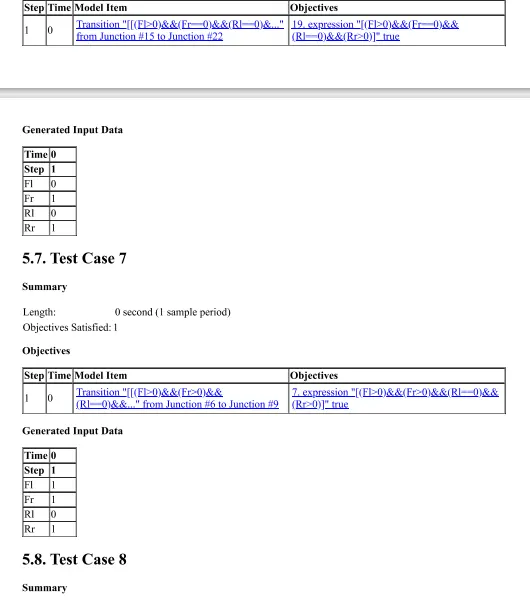
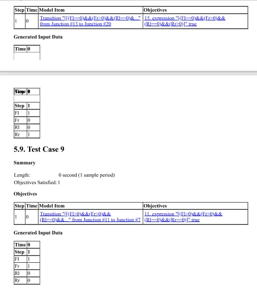
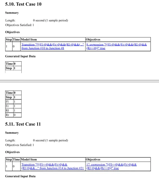
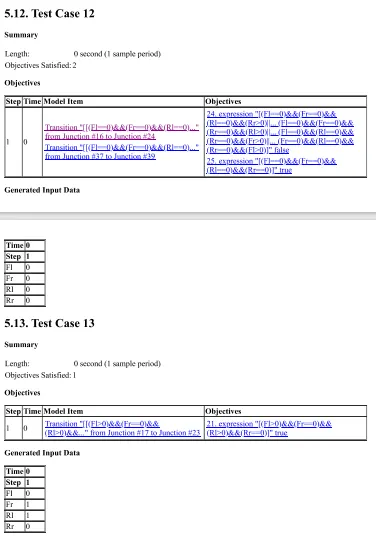
-Open the model>>Select 'Test Generation'>>Then 'Test generation setting'>> 'Advisor'>>Then 'Generate Test';
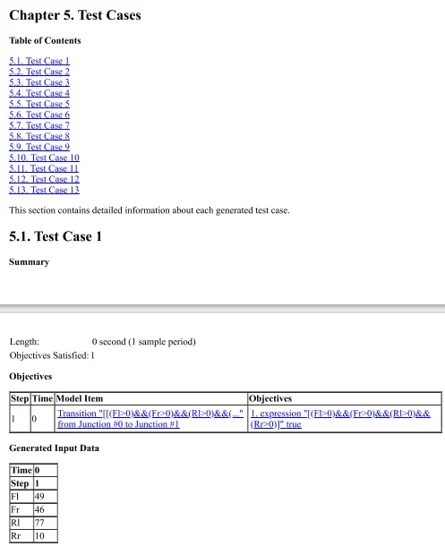
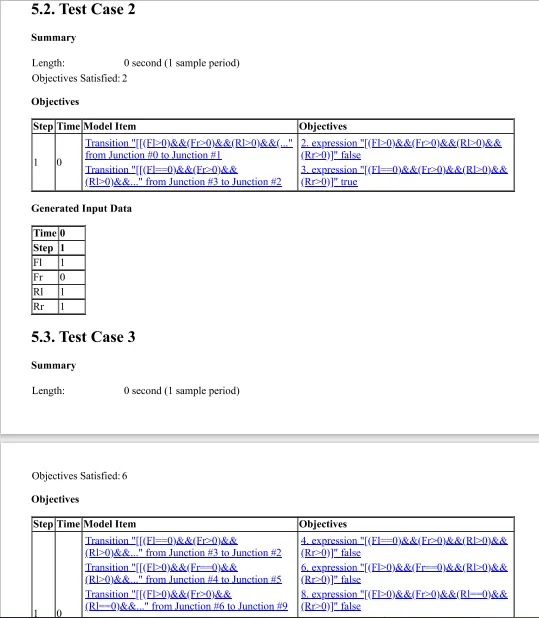
-Reports;
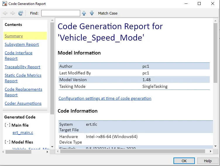
-Code Reports;
Vehicle_Speed_Mode.c
(103)
Highlighting: selected 11 blocks
1 / 108
/*

 * File: Vehicle_Speed_Mode.c

 *

 * Code generated for Simulink model 'Vehicle_Speed_Mode'.

 *

 * Model version                  : 1.48

 * Simulink Coder version         : 9.5 (R2021a) 14-Nov-2020

 * C/C++ source code generated on : Mon April 17 21:14:49 2023

 *

 * Target selection: ert.tlc

 * Embedded hardware selection: Intel->x86-64 (Windows64)

 * Code generation objectives: Unspecified

 * Validation result: Not run

 */


#include "Vehicle_Speed_Mode.h"

#include "Vehicle_Speed_Mode_private.h"


/* External outputs (root outports fed by signals with default storage) */

ExtY_Vehicle_Speed_Mode_T Vehicle_Speed_Mode_Y;


/* Real-time model */

static RT_MODEL_Vehicle_Speed_Mode_T Vehicle_Speed_Mode_M_;

RT_MODEL_Vehicle_Speed_Mode_T *const Vehicle_Speed_Mode_M =

  &Vehicle_Speed_Mode_M_;

real_T rt_roundd_snf(real_T u)

{

  real_T y;

  if (fabs(u) < 4.503599627370496E+15) {

    if (u >= 0.5) {

      y = floor(u + 0.5);

    } else if (u > -0.5) {

      y = u * 0.0;

    } else {

      y = ceil(u - 0.5);

    }

  } else {

    y = u;

  }


  return y;

}


/* Model step function */

void Vehicle_Speed_Mode_step(void)

{

  uint32_T tmp;


  /* Outputs for Atomic SubSystem: '/Vehicle_Speed_Mode' */

  /* Chart: '/Vehicle_Speed_Mode' incorporates:

   *  Inport: '/Fl'

   *  Inport: '/Fr'

   *  Inport: '/Rl'

   *  Inport: '/Rr'

   */

  if ((Fr > 0) && (Fl > 0) && (Rl > 0) && (Rr > 0)) {

    tmp = (uint32_T)Fr + Fl;

    if (tmp > 65535U) {

      tmp = 65535U;

    }


    tmp += Rl;

    if (tmp > 65535U) {

      tmp
Definition
Variable defined in Vehicle_Speed_Mode.c
47 uint32_T tmp;

 = 65535U;

    }


    tmp += Rr;

    if (tmp > 65535U) {

      tmp = 65535U;

    }


    /* Outport: '/Vehicle_Speed' */

    Vehicle_Speed_Mode_Y.Vehicle_Speed = (uint16_T)rt_roundd_snf((real_T)tmp /

      4.0);

  } else if ((Fr == 0) && (Fl > 0) && (Rl > 0) && (Rr > 0)) {

    tmp = (uint32_T)Fl + Rl;

    if (tmp > 65535U) {

      tmp = 65535U;

    }


    tmp += Fl;

    if (tmp > 65535U) {

      tmp = 65535U;

    }


    /* Outport: '/Vehicle_Speed' */

    Vehicle_Speed_Mode_Y.Vehicle_Speed = (uint16_T)rt_roundd_snf((real_T)tmp /

      3.0);

  } else if ((Fr > 0) && (Fl == 0) && (Rl > 0) && (Rr > 0)) {

    tmp = (uint32_T)Fr + Rl;

    if (tmp > 65535U) {

      tmp = 65535U;

    }


    tmp += Rr;

    if (tmp > 65535U) {

      tmp = 65535U;

    }


    /* Outport: '/Vehicle_Speed' */

    Vehicle_Speed_Mode_Y.Vehicle_Speed = (uint16_T)rt_roundd_snf((real_T)tmp /

      3.0);

  } else if ((Fr > 0) && (Fl > 0) && (Rl == 0) && (Rr > 0)) {

    tmp = (uint32_T)Fr + Fl;

    if (tmp > 65535U) {

      tmp = 65535U;

    }


    tmp += Rr;

    if (tmp > 65535U) {

      tmp = 65535U;

    }


    /* Outport: '/Vehicle_Speed' */

    Vehicle_Speed_Mode_Y.Vehicle_Speed = (uint16_T)rt_roundd_snf((real_T)tmp /

      3.0);

  } else if ((Fr > 0) && (Fl > 0) && (Rl > 0) && (Rr == 0)) {

    tmp = (uint32_T)Fr + Fl;

    if (tmp > 65535U) {

      tmp = 65535U;

    }


    tmp += Rl;
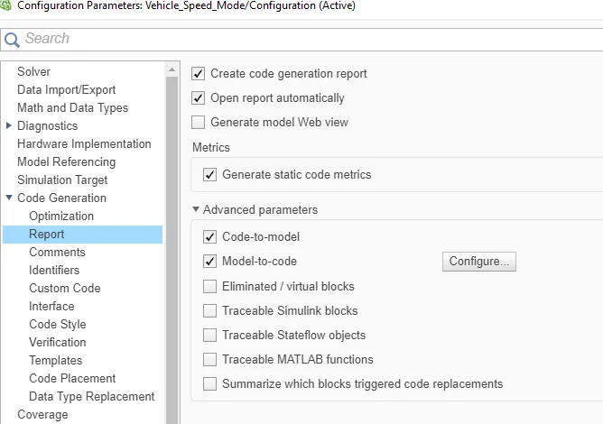
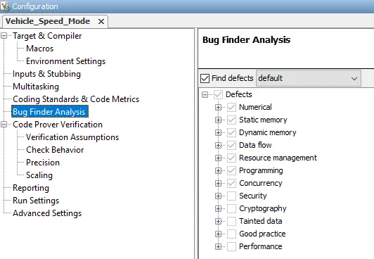
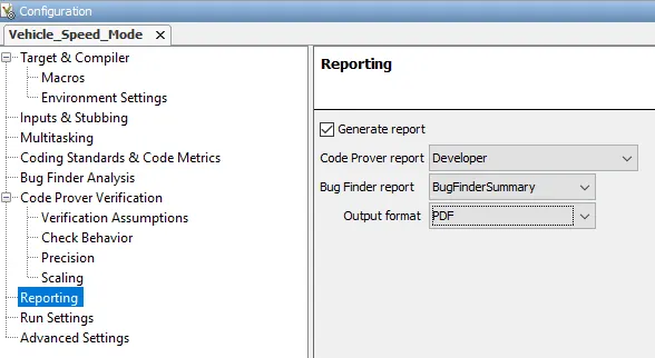
Â
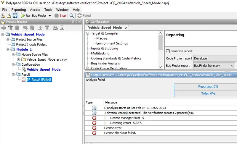
-Result:
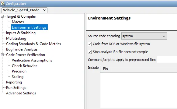
-Result:
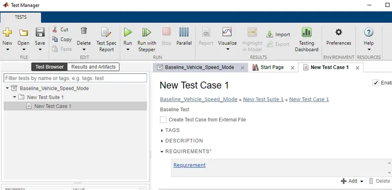
-Run Model>>Go to the simulink test manager>>Click on'New'>> test file'>>And create test name;
-Go to the Requirement;
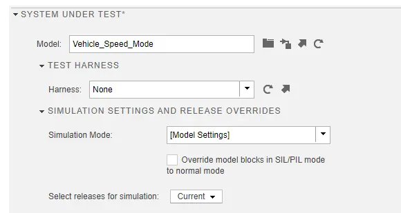
-Click on 'System under test';
-Click on 'Input';
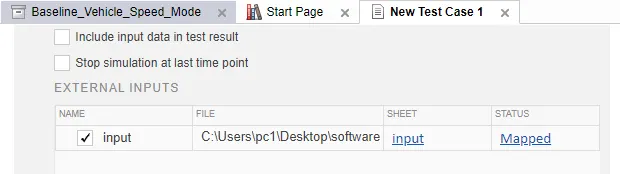
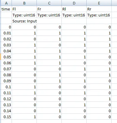
-Click on 'Baseline Criteria';
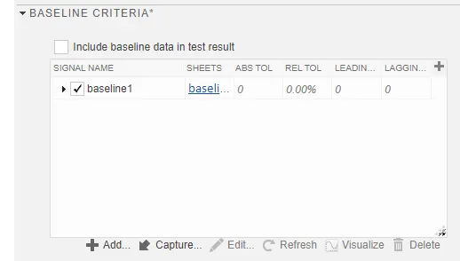
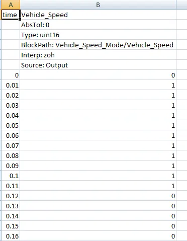
-Click on 'Coverage setting';
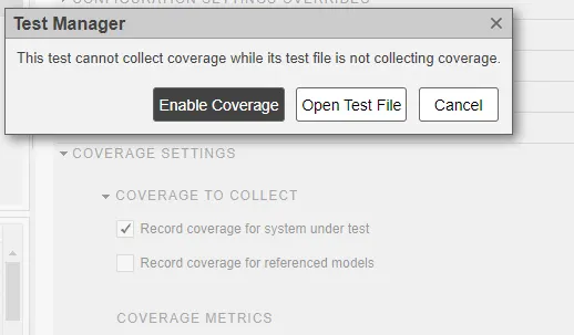
-Then save and Run the Test;
-Results:
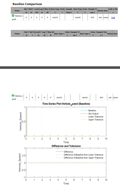
-Go to the sinulink test manager>>click on 'New'>Test file>>Again Click on 'New'>Test for model component>>Then make following settings>>Click 'Next' And 'Done' at final;
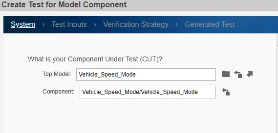
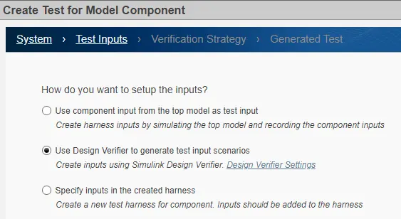
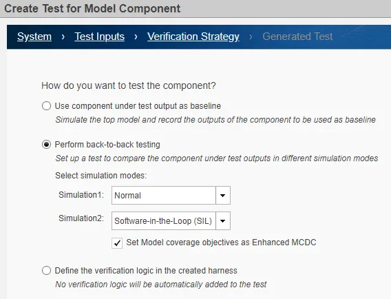
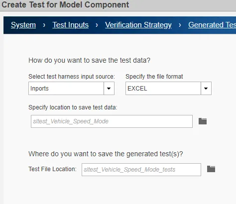
-Generated MIL And SIL model;
Â
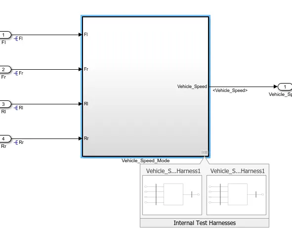
-Then Go to Requirements;
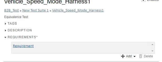
-Click on Coverage setting;
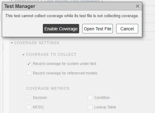
-Then Save and Run;
-Results;
-Equivalence criteria Results;
-For iteration1;
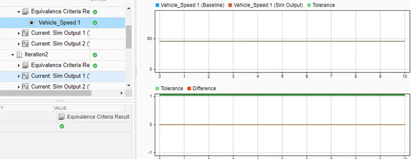
-MIL Output For iteration1;

Note: We can see results and output for other iteration in following attached report pdf.
-Report;
---------------------------------------------------------------------------------------------
Note: All files of results and generated reports are inserted below;