Project 1- Traffic Jam Assistant Feature
Problem Statement:
To develop one specific requirement of Traffic Jam Assistant algorithm which would predominantly feature in the IPC algorithm.Please note that the whole Traffic Jam Assistant is a very huge algorithm & only one small part of the logic is implemented here. Idea is to familiarize with concepts of Model Based Development in MATLAB Environment. The Project must be done keeping in mind the following processes & steps.
- This model must be developed in MATLAB Simulink as per MBD guidelines.
- Code Generation Profile must be in Embedded Coder.
- Simulink Data Dictionary must be created for the model & must be linked to the model.
- Model Advisor Report is mandatory & this will be followed by Code Generation.
General Overview:
Adaptive Cruise Control Feature for passenger cars allows the host vehicle to adapt to the speed in line with the flow of traffic. Driving in heavy traffic or keeping a safe distance to the preceding vehicle calls for a high level of concentration. The Adaptive Cruise Control feature can reduce the stress on the driver by automatically controlling the vehicle speed & maintaining a predefined minimum distance to the preceding vehicle. As a consequence, the driver enjoys more comfort & can concentrate on the road little better.
A radar sensor is usually at the core of the Adaptive Cruise Control. Installed at the front of the vehicle, the system permanently monitors the road ahead. As long as the road ahead is clear, cruise control feature maintains the speed set by the driver. If the system spots a slower vehicle within its detection range, it gently reduces speed by releasing the accelerator or actively engaging the brake control system. If the vehicle ahead speeds up or changes lanes, the cruise control automatically accelerates to the driver’s desired speed.
Standard Adaptive Cruise Control can be activated from speeds of around 30 km/h (20 mph) upwards and supports the driver, primarily on cross-country journeys or on freeways. The cruise control stop & go variant is also active at speeds below 30 km/h (20 mph). It can maintain the set distance to the preceding vehicle even at very low speeds and can decelerate to a complete standstill. When the vehicle remains stopped longer, the driver needs only to reactivate the system, for example by briefly stepping on the gas pedal to return to cruise control mode. In this way, cruise control stop & go supports the driver even in heavy traffic and traffic jams.
Since Adaptive Cruise Control is a comfort and convenience system, brake interventions and vehicle acceleration only take place within defined limits. Even with Adaptive Cruise Control switched on, it remains the driver’s responsibility to monitor the speed and distance from the vehicle in front.
Traffic Jam Assistant Feature
Introduction to the Feature:
Traffic Jam Assistant is one of the most common feature in Advanced Driver Assistance System. Traffic Jam Assistant helps the driver arrive more relaxed at their destination, even in dense traffic or in traffic jams. As a partially automated comfort function, the system takes over the longitudinal & lateral guidance of the vehicle. This means that the car can drive off, accelerate & brake automatically, as well as steer the vehicle within certain constraints. The driver has to permanently supervise the system & be ready to take over the complete control of the vehicle at any time.

Traffic Jam Assistant system helps to avoid rear end collisions in dense traffic conditions & traffic jams. In Traffic jams, the vehicle takes over driving off, acceleration, braking and steering within same lane.
Basic Working Principle:
Traffic Jam Assistant is based on the sensors and the functionality of the Adaptive Cruise Control (ACC) with stop & go and Lane Keeping Support (LKS). When ACC ‘Stop & Go’ is turned ON, the Traffic Jam Assistant continuously analyses the speed of the surrounding vehicles and compares it with the own driving speed. If the system detects dense traffic or a traffic jam at speeds less than 60 kmph, the driver can activate the functionality by press of a button. The vehicle will now automatically follow the vehicle in front, takes over driving off, acceleration, braking and steering within same lane.
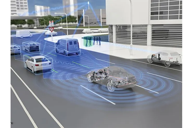
Information regarding the Traffic Jam Assistant will be available to be displayed to the driver in the Instrument Panel Cluster (IPC). The Algorithm which the students need to implement here in this project is predominantly based on IPC units.
1.AIM-
Model Development of a single feature of Traffic Jam Assist using MATLAB & Simulink as well as Code Generation using Embedded coder
Objective
Model Development as per MBD guidelines. Creation of Simulink Data Dictionary. Code Generation using Embedded Coder. Generating Model Advisor Report.
Main model:
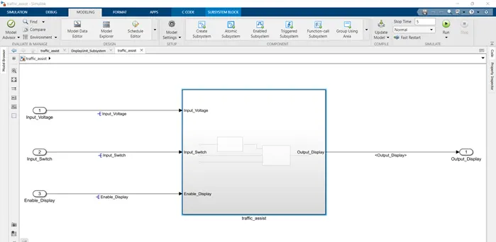
Requirement No 1:
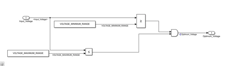
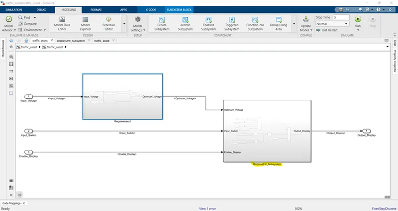
Input Signal “Input_Voltage” is compared against voltage values “VOLTAGE_MINIMUM_RANGE” & “VOLTAGE_MAXIMUM_RANGE”. Incoming input signal “Input_Voltage” must be greater than – equal to “VOLTAGE_MINIMUM_RANGE” and less than – equal to “VOLTAGE_MAXIMUM_RANGE”. Output signal from here is “Optimum_Voltage” which will be one of the inputs to the subsystem “DisplayUnit”.
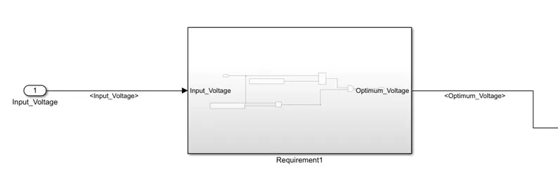
Inside the subsystem requirement1:
Requirement No 2 (DisplayUnit Subsystem):
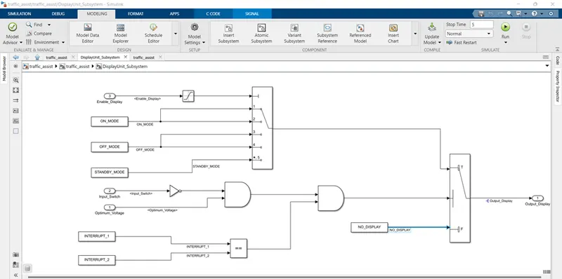
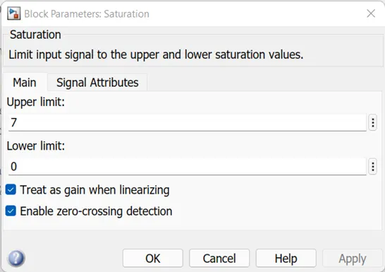
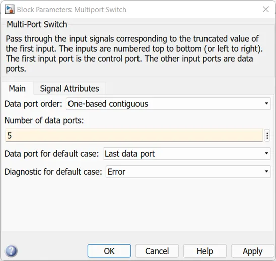
Input Signals are “Optimum_Voltage”, “Input_Switch”,“Enable_Display”. Signal “Enable_Display” must be saturated between the range 0 – 7. Output signal from the subsystem is “Output_Display”. Input Signal “Enable_Display” is compared against pre – defined set of values in a multiport switch. Total data ports in the multiport switch is 5. Multiport switch inputs 1 & 2 is connected to calibration signal “ON_MODE”, Multiport switch inputs 3 & 4 is connected to calibration signal “OFF_MODE” while Multiport switch input 5 is connected to calibration signal “STANDBY_MODE”. The output from Multiport switch is connected to the first input port of the Switch block. The third input port of the Switch block is connected to the calibration signal “NO_DISPLAY”. Meanwhile NOT value of input signal “Input_Switch” is compared in an AND gate against input signal “Optimum_Voltage” and the output from comparing if calibration signals “INTERRUPT_1” & “INTERRUPT_2” are equal. The output of the AND gate is the second input of the switch block. The output from the switch block is “Output_Display”
Inside the requirement2 subsystem (DisplayUnit_subsystem):
The saturation limit condition given in the requirement documentation:
Multiport switch properties:
After the subsystems are created the requirement tagging of the subsystems need to be done. This is basically connecting the word document that has the specifications of how these susbsystems are created along with the logic the susbsystem should be implemented.
Requirement tagging:
Once the subsystem is created and named, the requirement tagging is done. Usually the requirement document is a word file and the rule is to keep both the word document and the '.slx model in the same folder. This is because if the document and the model are not inside the same folder then the requirement tagging can not be done and will show error.
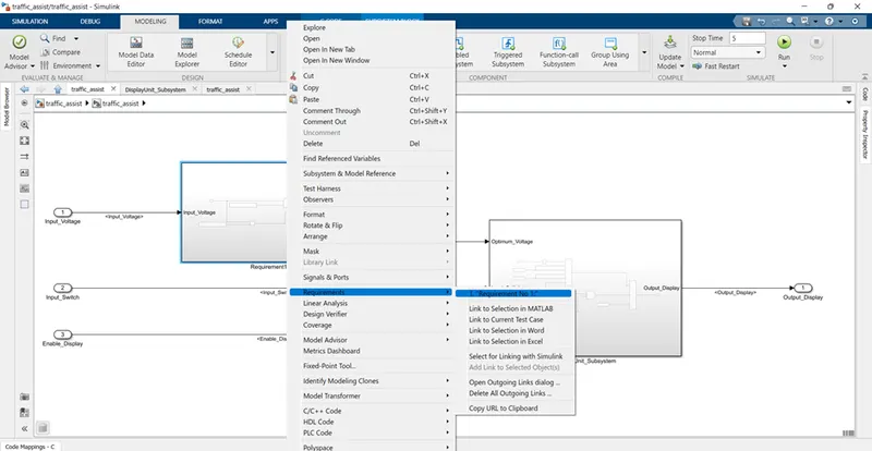
When the requirement is linked from the word file it shows the linked word in the requirement dropdown indicating that the word file is tagged.
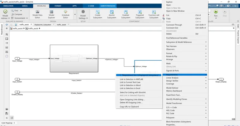
- Open the word file highlight the Requirement section that needs to be tagged. Only one requirement can be tagged per subsystem to avoid confusion.
- Rename the subsystem. Right click on the subsystem ---->requirements--->link to selection on word. And the block turns yellow. The same steps are carried out for Requirement-2 . Once the tagging is done all the blocks when viewing the requirment turns orange and it opens the document linked with the block.
Once the requirement tagging is done the tracibility file is created for linking the external documents with matlab/simulink model.
Ater creating the models the model will throw an output error if we simulate it as such. This is because all the parameters specified in the model are not defined. To define these inputs and outputs you need to create a sldd file.
SIMULINK DATA DICTIONARY:
In model based designing the most important part is creating a sldd file. This is actually similar to how we declare variables in model and base workspace. But the workspace only provide declarations. Unlike initialisation in workspace we can define data related parameters in sldd file and save it. This can be transfered to another model by having the model file and sldd file under the same path directory.
How to access sldd?
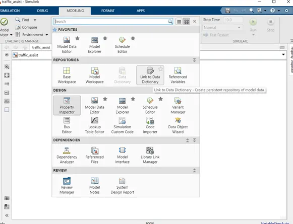
To create a sldd for first time or access previously stored files go to modelling--->link to data dictionary, a pop up will be appear as shown below.
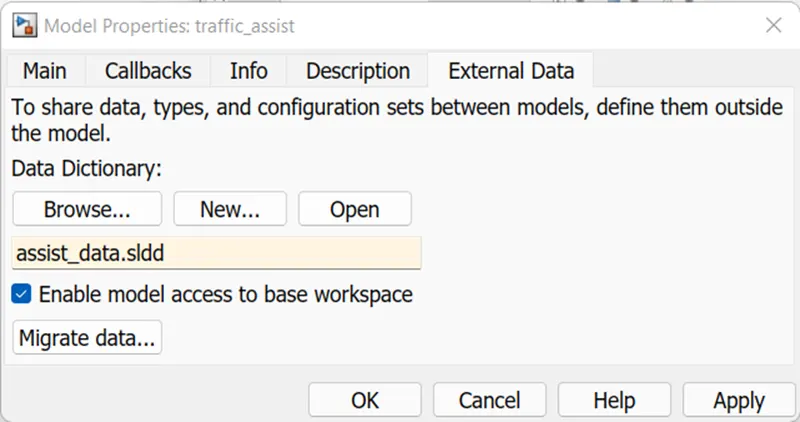
click on External data tab the message displayed above appears. To create a new sldd file use New option or click on browse to access previously created files. When either of these steps are completed the file name is displayed below, disable the model access to base workspace and proceed with the confirmation button. By doing this it links the model and the data dictionary.
In general the model explorer will be opened. We can also see that there is external data name on the model hierarchy box with a different icon. This is where we are going to create out sldd file for different types of inputs.
Input Signals:
|
Name of the Signal |
Data Type |
Range |
|
Input_Voltage |
uint8 |
0 - 255 |
|
Input_Switch |
boolean |
0 – 1 |
|
Enable_Display |
uint8 |
0 - 255 |
Output Signal:
|
Name of the Signal |
Data Type |
Range |
|
Output_Display |
uint8 |
0 - 255 |
Calibration Signals:
|
Name of the Signal |
Data Type |
Range |
Initial Value |
|
VOLTAGE_MINIMUM_RANGE |
uint8 |
0 – 255 |
30 |
|
VOLTAGE_MAXIMUM_RANGE |
uint8 |
0 – 255 |
50 |
|
OFF_MODE |
uint8 |
0 – 255 |
2 |
|
ON_MODE |
uint8 |
0 – 255 |
1 |
|
STANDBY_MODE |
uint8 |
0 – 255 |
3 |
|
INTERRUPT_1 |
boolean |
0 – 1 |
1 |
|
INTERRUPT_2 |
boolean |
0 - 1 |
1 |
|
NO_DISPLAY |
uint8 |
0 – 255 |
0 |
Local Signal:
|
Name of the Signal |
Data Type |
Range |
|
Optimum_Voltage |
boolean |
0 - 1 |
The data specified above is filled in the corresponding columns as shown below.
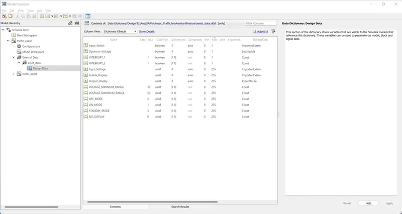
Access sldd: click on modelling tab--->design dropdown---->link to data dictionary.
The properties window will pop-up, external data--->new--->name the file--->save--->add path uncheck the 'enable model access to base workspace'.
This opens the model explorer and provides a space to create these variables for the model.
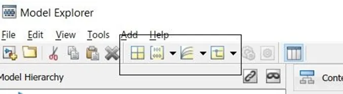
The sldd file is attached below for reference. Each data differ based on type property their behavioural output. To add inputs in the model explorer on the tool strip click on the icons highlighted below or select Add and from the drop down select the required input. The main point to be noted is to check for the values of resolution, storage class. The resolution reduces the complex calculation errors when prioritized. In case we have to multiply different decimal pointed numbers when having high resolution helps to reduce the error in the answer and gives precise values after decimal point. On the other hand the storage class plays a vital role in code generation, since the file format given there will be used to group those files under the same class and object, when this is not specified properly the model may through an error/ warning or the accuracy of the model itself will be reduced. For complex modelling it is always advised to have resolution and storage class.
Case-i:
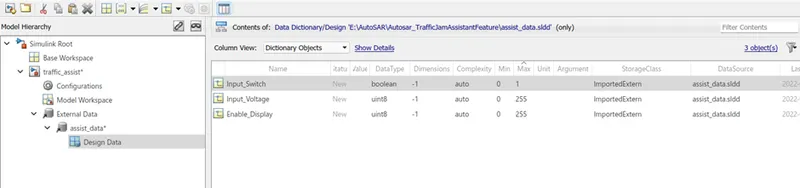
For inputs: Simulink signals, storage class : ImportedExtern
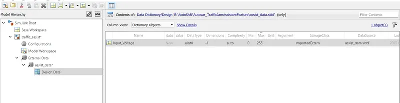
As shown below the name is typed and the values are filled in the respective column. The storage class for the input signals are ImportedExtern. After giving the required inputs select apply, else the changes might not be saved. The same goes for all the remaining signals.
Case-ii:
For output: output signals, storage class: Export to file
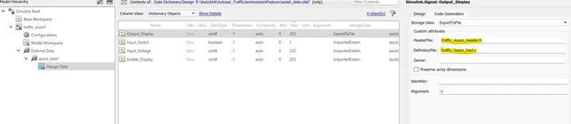
The same steps are followed as discussed in the case-i but when the signal is an output signal it needs to be associated with the header and the definition file. Any names can be given to the header file and the extension should be "filename.h". Similarly for the definition file it is "filename.c". By doing this all the signals and the variables will be grouped under the given file names and easy to access or it might not be classified properly and model might throw an error.
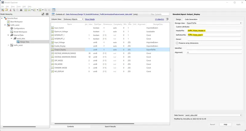
Same goes for calibration signals. Storage class: const , also you need to define the header and definition files.
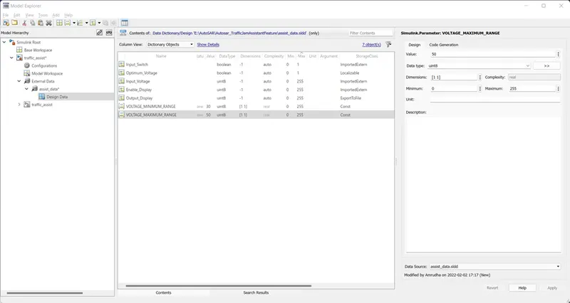
By doing this we have defined our sldd for the model. Now the model can have their block names and signal names along with the values fed to it by signal resolving and propagation.
Signal Resolving:
Resolving a signal is to ensure that the signal is present in the model and included in the sldd file so that it contains all the values when propogated to other blocks and subsystems.
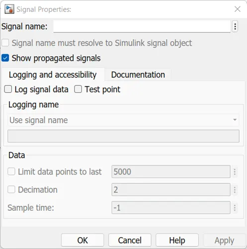
Right click on the required signal---->give signal name --->check 'signal name must resolve to simulink signal object' and apply the changes to your model.
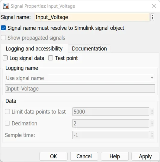
you will get the symbol and the signal name on the line as shown below. This process is called signal resolving.
Resolving a signal needs to be done whenever the signal appears for the first time in the model. All the input signals are resolved as shown above.
An error message may pop up or the block will remain in red color highlighted outline when the inputs are not mentioned in the sldd file.
Signal Propagation:
Once the signal is resolved the same value needs to be carried or preserved through out the model when the same input is given to different system, so to carry the signal as the same propagation is used.
To do propagation : right click on signal line--->properties---->check on 'show propagated signals'--->ok
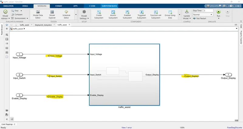
The input signals that appear for first time are resolved(to the left of the subsystem) and the output signal which has already appeared inside the model is propagated outside( to the right of the subsystem).
All the signal names in the angluar brackets<> are propagated signals.
All the signals that are first resolved are then propogated in the model based designing.
Configuration paramters required to be changed for the model as shown below to generate the c code using the embedded coder.
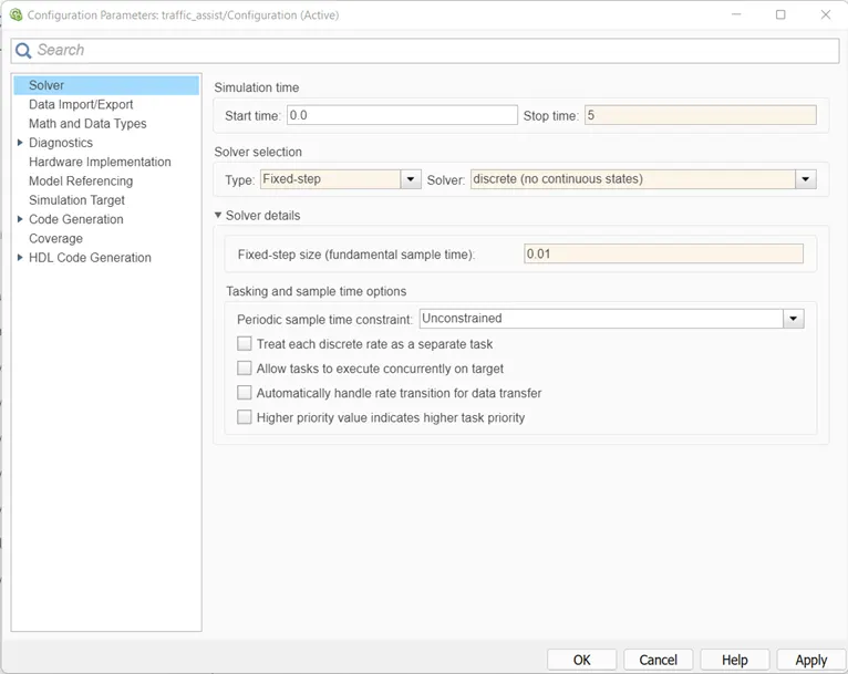
By default grt.tlc will be present as the target file change it to ert.tlc file as shown below
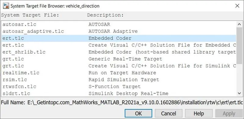
The toolchain is choosen based one the requirement either auto or specific compiler to build the code.
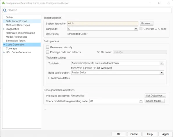
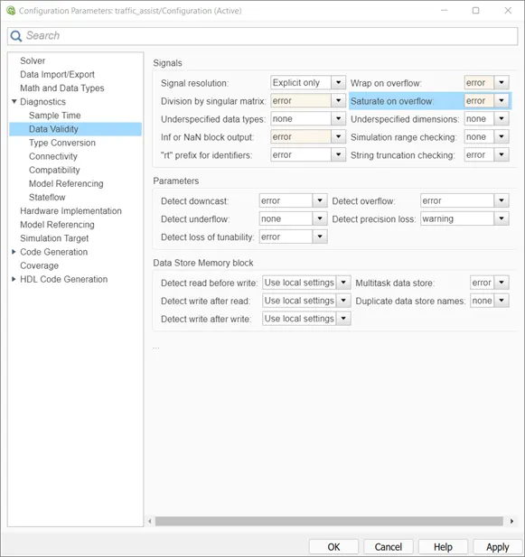
After the changes are made the model is saved and runned.
MODEL ADVISOR CHECK:
This is done to know if the model is built correctly or not. This have certain guidelines for our models and checks if those are satisfied . Once the advisor check is cleared your model is ready for code generation.
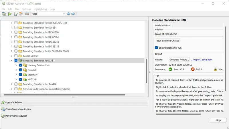
go to Modelling tab--->model advisor (the pop-up shown below appears.)
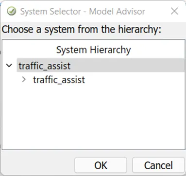
Once the system is selected the next window opens:
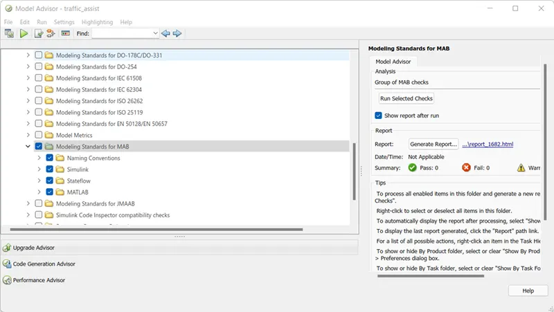
The modelling standards under the "by task" option is checked and the model runs for the selected checks. A report similar the one shown below is generated. The report is attached below for reference. Here only the start page is shown.
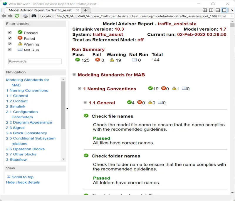
The model advisor report is attached for refernce below.
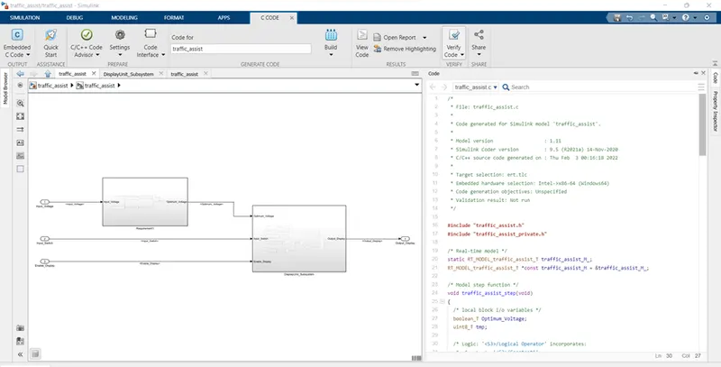
The tool strip appears with the build option and your code is generated. Only one snap is attached below. Refer the document for the generated c-code using embedded coder.
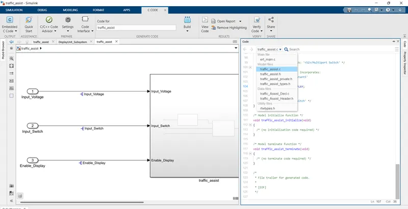
The header and definition files included in the storage class can be seen here in code generation. Thus it is important to define those files to convert our model in a c code
Code:
/*
 * File: traffic_assist.c
 *
 * Code generated for Simulink model 'traffic_assist'.
 *
 * Model version                  : 1.11
 * Simulink Coder version         : 9.5 (R2021a) 14-Nov-2020
 * C/C++ source code generated on : Thu Feb  3 00:16:18 2022
 *
 * Target selection: ert.tlc
 * Embedded hardware selection: Intel->x86-64 (Windows64)
 * Code generation objectives: Unspecified
 * Validation result: Not run
 */

#include "traffic_assist.h"
#include "traffic_assist_private.h"

/* Real-time model */
static RT_MODEL_traffic_assist_T traffic_assist_M_;
RT_MODEL_traffic_assist_T *const traffic_assist_M = &traffic_assist_M_;

/* Model step function */
void traffic_assist_step(void)
{
  /* local block i/o variables */
  boolean_T Optimum_Voltage;
  uint8_T tmp;

  /* Logic: '<S3>/Logical Operator' incorporates:
   *  Constant: '<S3>/Constant1'
   *  Constant: '<S3>/VOLTAGE_MINIMUM_RANGE'
   *  Inport: '<Root>/Input_Voltage'
   *  RelationalOperator: '<S3>/Relational Operator'
   *  RelationalOperator: '<S3>/Relational Operator1'
   */
  Optimum_Voltage = ((Input_Voltage >= VOLTAGE_MINIMUM_RANGE) && (Input_Voltage <=
    VOLTAGE_MAXIMUM_RANGE));

  /* Switch: '<S2>/Switch' incorporates:
   *  Constant: '<S2>/Constant3'
   *  Constant: '<S2>/Constant4'
   *  Inport: '<Root>/Input_Switch'
   *  Logic: '<S2>/AND'
   *  Logic: '<S2>/AND1'
   *  Logic: '<S2>/Logical Operator'
   *  RelationalOperator: '<S2>/Relational Operator'
   */
  if ((!Input_Switch) && Optimum_Voltage && (INTERRUPT_1 == INTERRUPT_2)) {
    /* Saturate: '<S2>/Saturation' incorporates:
     *  Inport: '<Root>/Enable_Display'
     */
    if (Enable_Display < 7) {
      tmp = Enable_Display;
    } else {
      tmp = 7U;
    }

    /* End of Saturate: '<S2>/Saturation' */

    /* MultiPortSwitch: '<S2>/Multiport Switch' */
    switch (tmp) {
     case 1:
      /* Switch: '<S2>/Switch' incorporates:
       *  Constant: '<S2>/Constant1'
       */
      Output_Display = ON_MODE;
      break;

     case 2:
      /* Switch: '<S2>/Switch' incorporates:
       *  Constant: '<S2>/Constant1'
       */
      Output_Display = ON_MODE;
      break;

     case 3:
      /* Switch: '<S2>/Switch' incorporates:
       *  Constant: '<S2>/Constant'
       */
      Output_Display = OFF_MODE;
      break;

     case 4:
      /* Switch: '<S2>/Switch' incorporates:
       *  Constant: '<S2>/Constant'
       */
      Output_Display = OFF_MODE;
      break;

     default:
      /* Switch: '<S2>/Switch' incorporates:
       *  Constant: '<S2>/Constant2'
       */
      Output_Display = STANDBY_MODE;
      break;
    }

    /* End of MultiPortSwitch: '<S2>/Multiport Switch' */
  } else {
    /* Switch: '<S2>/Switch' incorporates:
     *  Constant: '<S2>/Constant5'
     */
    Output_Display = NO_DISPLAY;
  }

  /* End of Switch: '<S2>/Switch' */
}

/* Model initialize function */
void traffic_assist_initialize(void)
{
  /* (no initialization code required) */
}

/* Model terminate function */
void traffic_assist_terminate(void)
{
  /* (no terminate code required) */
}

/*
 * File trailer for generated code.
 *
 * [EOF]
 */
The code is generated for the model along with the header and definition files we created using the sldd.
Conclusion: Thus the model is read and built according to the requirement document. Model simulated without any errors and the code is built for the model from the embedded coder and displayed.