Project 1- Traffic Jam Assistant Feature
just understanding the Traffic Jam Assistant Feature and Basic Working Principle Information regarding the Traffic Jam Assistant will be available to be displayed to the driver in the Instrument Panel Cluster (IPC). The Algorithm which the students need to implement here in this project is predominantly based on IPC units.
and requirement's clearly readinf
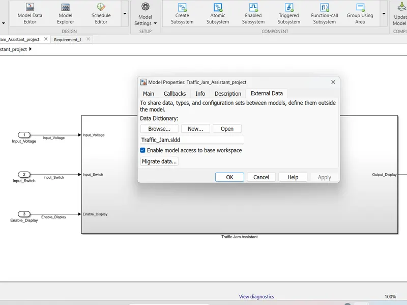
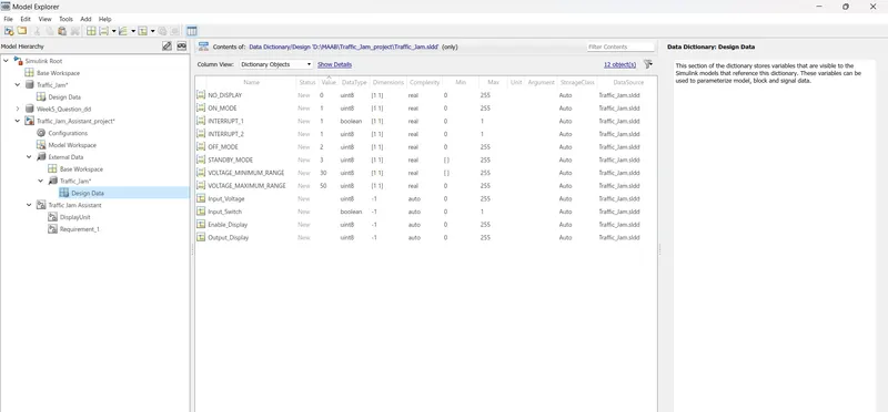
next we have to create SLDD file for the project as given below and file will submmisted in the attachments
Input Signals:
|
Name of the Signal |
Data Type |
Range |
|
Input_Voltage |
uint8 |
0 - 255 |
|
Input_Switch |
boolean |
0 – 1 |
|
Enable_Display |
uint8 |
0 - 255 |
are taking as input signal for sub system
Output Signal:
|
Name of the Signal |
Data Type |
Range |
|
Output_Display |
uint8 |
0 - 255 |
using these all requirement i have create the sub system that is given beloew
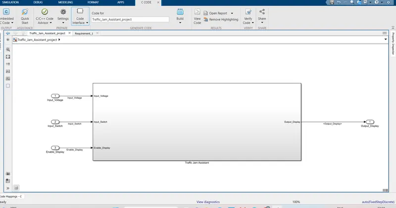
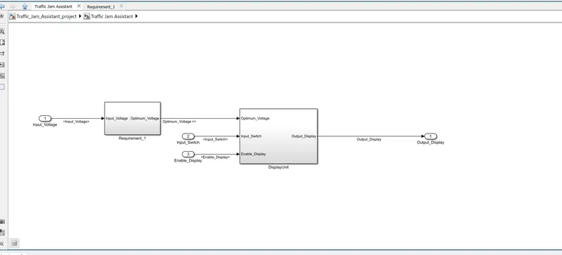
now look in to requiremnets
Requirement No 1:
- Input Signal “Input_Voltage” is compared against voltage values “VOLTAGE_MINIMUM_RANGE” & “VOLTAGE_MAXIMUM_RANGE”.
- Incoming input signal “Input_Voltage” must be greater than – equal to “VOLTAGE_MINIMUM_RANGE” and less than – equal to “VOLTAGE_MAXIMUM_RANGE”.
- Output signal from here is “Optimum_Voltage” which will be one of the inputs to the subsystem “DisplayUnit”
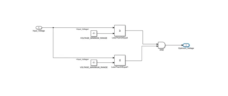
Requirement No 2 (DisplayUnit Subsystem):
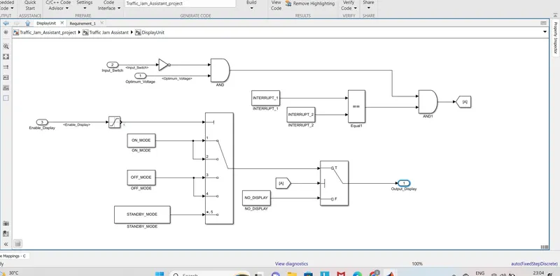
- Input Signals are “Optimum_Voltage”, “Input_Switch”,“Enable_Display”. Signal “Enable_Display” must be saturated between the range 0 – 7. Output signal from the subsystem is “Output_Display”.
- Input Signal “Enable_Display” is compared against pre – defined set of values in a multiport switch. Total data ports in the multiport switch is 5.
- Multiport switch inputs 1 & 2 is connected to calibration signal “ON_MODE”, Multiport switch inputs 3 & 4 is connected to calibration signal “OFF_MODE” while Multiport switch input 5 is connected to calibration signal “STANDBY_MODE”.
- The output from Multiport switch is connected to the first input port of the Switch block. The third input port of the Switch block is connected to the calibration signal “NO_DISPLAY”.
- Meanwhile NOT value of input signal “Input_Switch” is compared in an AND gate against input signal “Optimum_Voltage” and the output from comparing if calibration signals “INTERRUPT_1” & “INTERRUPT_2” are equal. The output of the AND gate is the second input of the switch block.
- The output from the switch block is “Output_Display”.
considering above the requirment i have construct asub system taht is show in below.
and finnaly SLDD file is tagging to model and sldd file is also attached
MODEL ADVISORY CHECK:
after finishing the model based MMAAB check line are checked here i have sharing the report also
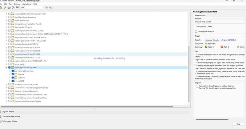
when the running the model some waring are came that are corrected it.
CODE GENERATIONS 0
after finshing the model MAAB chck next go for cide generation
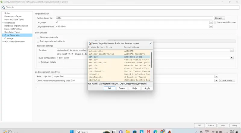
here i am selecting the ert.tLC
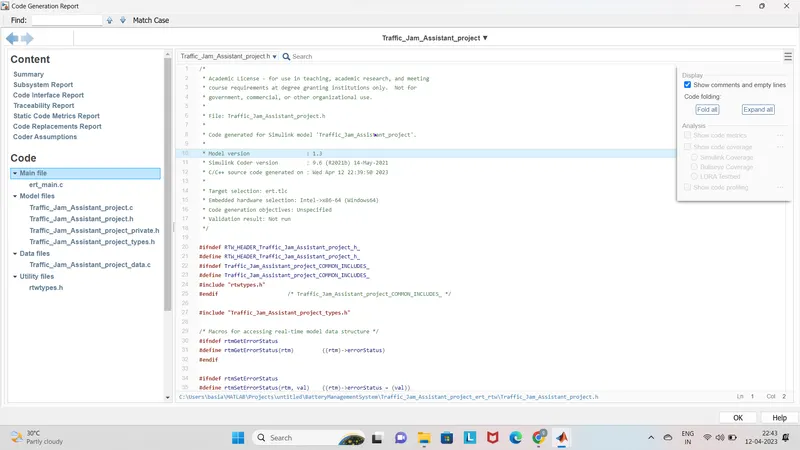
code file is submitted in the below.
blocks are used in this priject
in, out, saturation,sub system,logical operators,switch, multiport swith, realtional operators , constant from and goto