Project 1- Traffic Jam Assistant Feature
Objectives:
- To develop one specific requirement of Traffic Jam Assistant algorithm which would predominantly feature in the IPC algorithm.
- To develop Simulink model as per MBD requirements, Code Generation Profile in Embedded Coder, create Simulink Data Dictionary and generate Model Advisor Report according to MAAB guidelines.
Traffic Jam Assistant:
- Traffic Jam Assist combines a full speed range Adaptive Cruise Control system with Auto-Go capability, together with a full speed Lane Keeping Assist system. The driving path may also be defined by the trajectory of the preceding vehicle under certain circumstances such as low-speed, dense traffic situations and missing lane markers. The extended variant of the system will also be able to assist the driver in construction sites with reduced lateral space.
- Information regarding the Traffic Jam Assistant will be available to be displayed to the driver in the Instrument Panel Cluster (IPC).
- IPC or Vehicle Dashboard, is one of the few devices with which the vehicle communicates to the driver.
- In this project, the algorithm is implemented based on IPC units.
Simulink Model:
- Consist of Three inputs- Input_Voltage, Input_Switch, Enable_Display and an output-Output_Display.
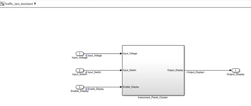
- Instrument_Panel_Cluster subsytem consist of two subsytems as per requirement document.
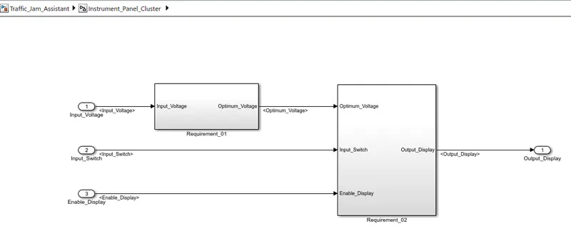
Requirement No 1:
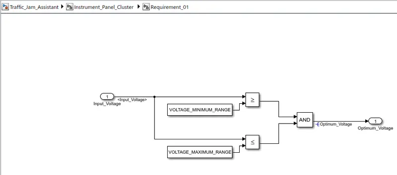
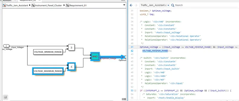
- Input Signal “Input_Voltage” is compared against voltage values “VOLTAGE_MINIMUM_RANGE” & “VOLTAGE_MAXIMUM_RANGE”.
- Incoming input signal “Input_Voltage” must be greater than – equal to “VOLTAGE_MINIMUM_RANGE” and less than – equal to “VOLTAGE_MAXIMUM_RANGE”.
- Output signal from here is “Optimum_Voltage” which will be one of the inputs to the subsystem “DisplayUnit”.
Requirement No 2 (DisplayUnit Subsystem):
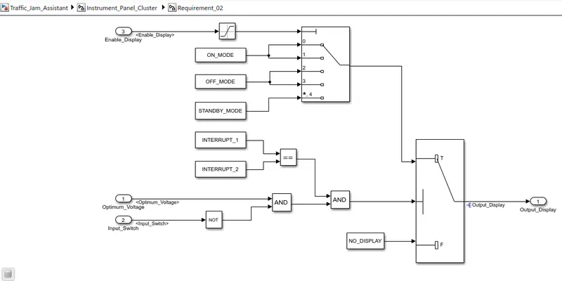
- Input Signals are “Optimum_Voltage”, “Input_Switch”,“Enable_Display”. Signal “Enable_Display” must be saturated between the range 0 – 7. Output signal from the subsystem is “Output_Display”.
- Input Signal “Enable_Display” is compared against pre – defined set of values in a multiport switch. Total data ports in the multiport switch is 5.
- Multiport switch inputs 1 & 2 is connected to calibration signal “ON_MODE”, Multiport switch inputs 3 & 4 is connected to calibration signal “OFF_MODE” while Multiport switch input 5 is connected to calibration signal “STANDBY_MODE”.
- The output from Multiport switch is connected to the first input port of the Switch block. The third input port of the Switch block is connected to the calibration signal “NO_DISPLAY”.
- Meanwhile NOT value of input signal “Input_Switch” is compared in an AND gate against input signal “Optimum_Voltage” and the output from comparing if calibration signals “INTERRUPT_1” & “INTERRUPT_2” are equal. The output of the AND gate is the second input of the switch block.
- The output from the switch block is “Output_Display”.
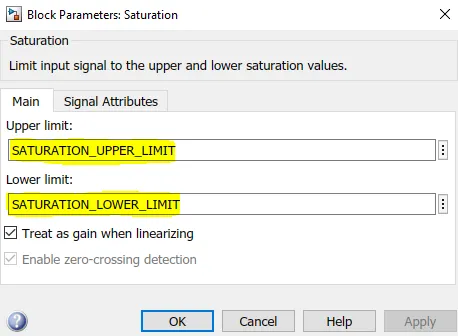
- Enable signal is saturated between 0 to 7 using Saturation Block and values are defined in SLDD as shown below:
Simulink Data Dictionary (SLDD):
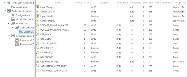
- As per requirement, all signals and constants are defined in Simulink Data Dictionary (SLDD).
- For input signals-Storage class is ImportedExtern, For output signal- Storage class is ExportedGlobal, For local signals- Storage class is Localizable and For constants- Storage class is Const.
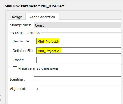
- For code generation, Header and definition files are defined as shown below:
Requirement Tagging:
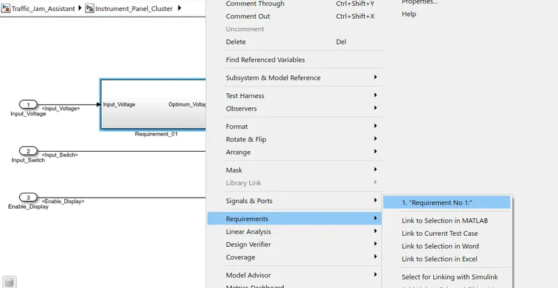
- Select the Requirement name from the word file
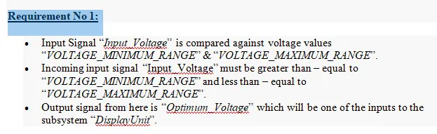
- Right click on the 'Requirement_01' subsytem and goto 'Requirements>> Link to Selection in Word'.
Model Settings:
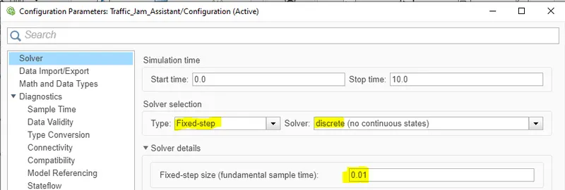
- Solver: Fixed-step discrete solver with step size of 0.01
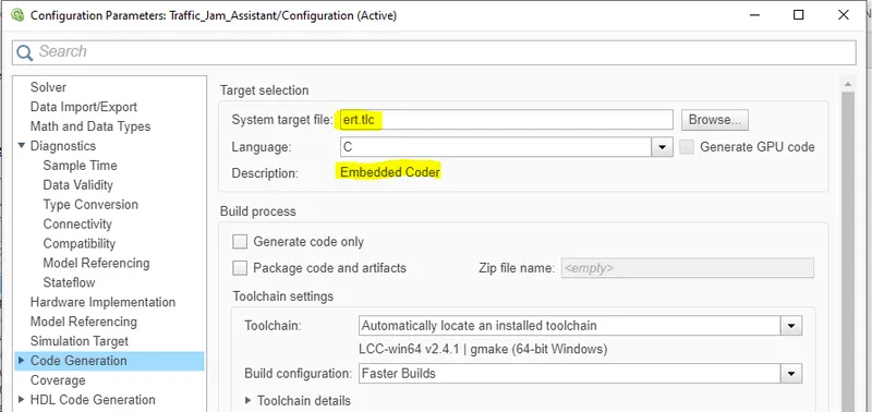
- Code generation: Selected the system file as ert.tlc which is for Embedded coder.
Code Generation:
- For code generation, Goto APPS and click on Embedded coder:

- under C CODE, click on Build option:

- Main file, Model files, Data files and Utility files will generate as shown below:
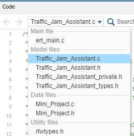
- Data Files:
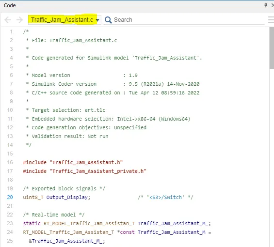
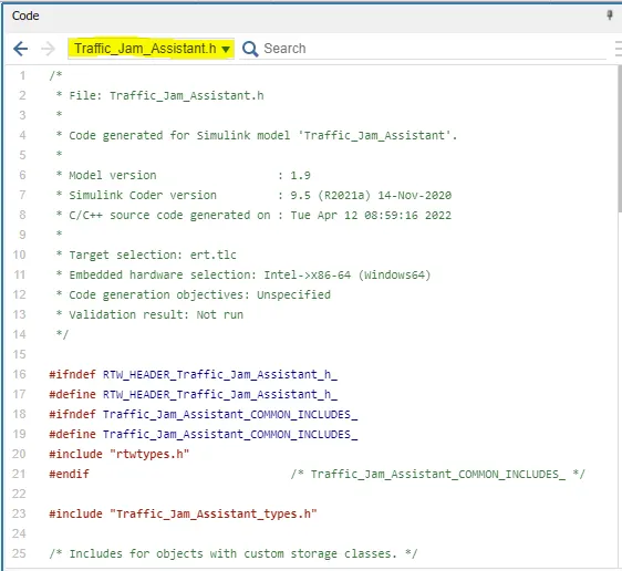
- We can also trace model with code generation as shown below:
Model Advisor Report:
- Under Modelling, click on Model Advisor:

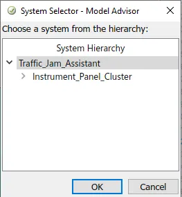
- Select the top level hierarchy:
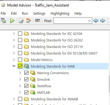
- Under Task, select Modeling Standards for MAB:
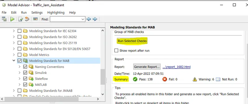
- Run selected checks; In summary, no of pass, fail, warning and Not rum will display.
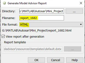
- To generate Report, click on 'Generate Report' and select desired format as shown below:
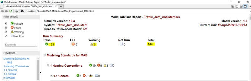
- Generated Report: Have 138 pass tests out of 144 total tests and 6 warnings.
Conclusion:
- Simulink modelling, Requirement Tagging, Code Generation, SLDD and Model advisor Report all the processes of MBD are performed.
- In Model advisor Report, 138 out of 144 test passed with 6 warnings according to MAAB guidelines.