Project 1- Traffic Jam Assistant Feature
Step 1) Creating the sldd file for the given variables
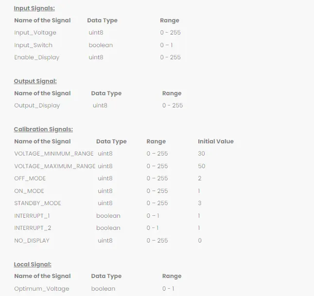
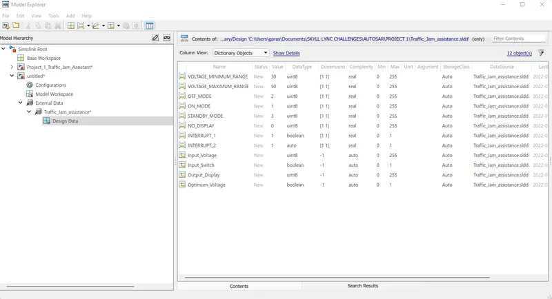
Step 2) Prepare the model as per the requirement 1 and form it as a subsystem
Requirement No 1:
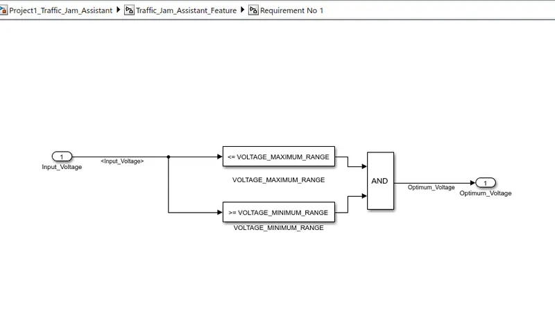
- Input Signal “Input_Voltage” is compared against voltage values “VOLTAGE_MINIMUM_RANGE” & “VOLTAGE_MAXIMUM_RANGE”.
- Incoming input signal “Input_Voltage” must be greater than – equal to “VOLTAGE_MINIMUM_RANGE” and less than – equal to “VOLTAGE_MAXIMUM_RANGE”.
- Output signal from here is “Optimum_Voltage” which will be one of the inputs to the subsystem “DisplayUnit”.

Step 3) Prepare the model as per the requirement 2 and form it as a subsystem
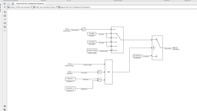
- Input Signals are “Optimum_Voltage”, “Input_Switch”,“Enable_Display”. Signal “Enable_Display” must be saturated between the range 0 – 7. Output signal from the subsystem is “Output_Display”.
- Input Signal “Enable_Display” is compared against pre – defined set of values in a multiport switch. Total data ports in the multiport switch is 5.
- Multiport switch inputs 1 & 2 is connected to calibration signal “ON_MODE”, Multiport switch inputs 3 & 4 is connected to calibration signal “OFF_MODE” while Multiport switch input 5 is connected to calibration signal “STANDBY_MODE”.
- The output from Multiport switch is connected to the first input port of the Switch block. The third input port of the Switch block is connected to the calibration signal “NO_DISPLAY”.
- Meanwhile NOT value of input signal “Input_Switch” is compared in an AND gate against input signal “Optimum_Voltage” and the output from comparing if calibration signals “INTERRUPT_1” & “INTERRUPT_2” are equal. The output of the AND gate is the second input of the switch block.
- The output from the switch block is “Output_Display”.
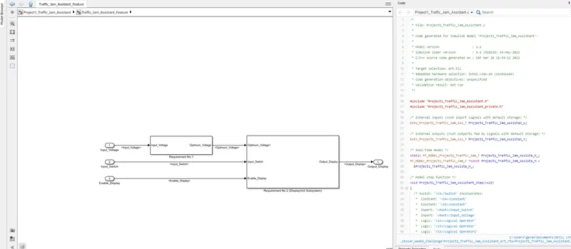
6) After creating the subsystem for requirement2 , combine requirement 1 & 2 and give names to the respective signals as per their port of origin and propagate the respective signals.
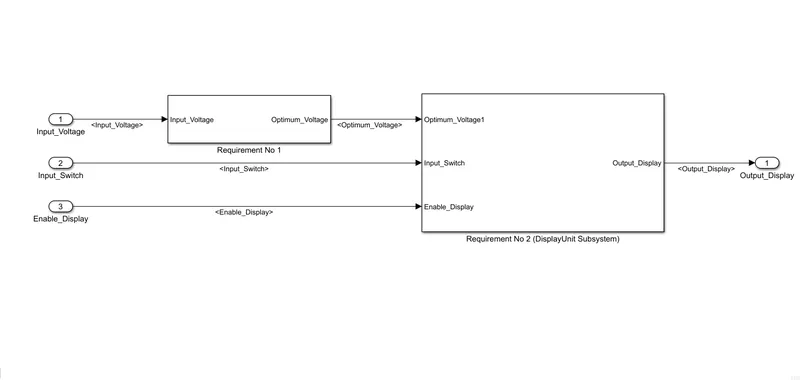
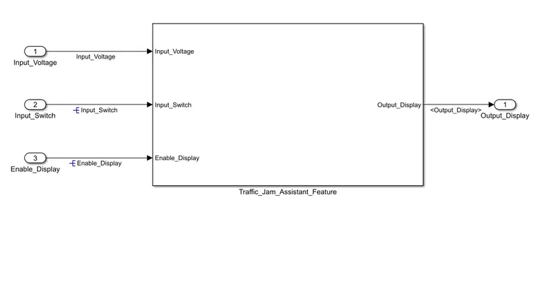
Making the subsystem for the both combined requirement the final model of the system will look as shown below.
Also resolve the signals.
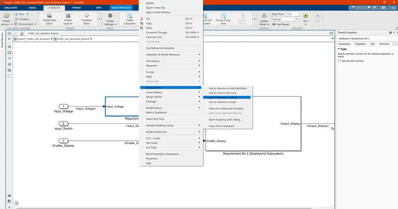
7) Now link the requirement document to the respective the subsystem.
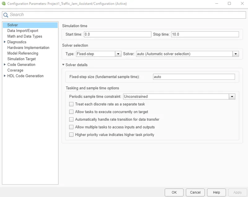
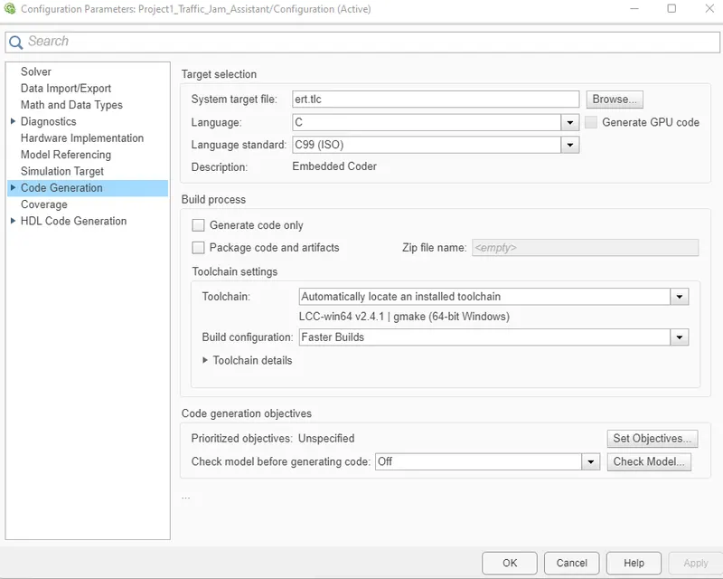
8) make the necessary changes in the configuration parameters. like taking fixed step and using ert.tlc for c code
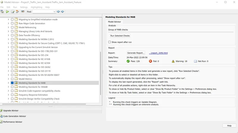
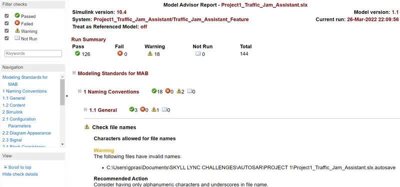
9) Run the model advisory and generate the report
10) Run the c code generator
/*
 * File: Project1_Traffic_Jam_Assistant.c
 *
 * Code generated for Simulink model 'Project1_Traffic_Jam_Assistant'.
 *
 * Model version                  : 1.1
 * Simulink Coder version         : 9.6 (R2021b) 14-May-2021
 * C/C++ source code generated on : Sat Mar 26 22:34:12 2022
 *
 * Target selection: ert.tlc
 * Embedded hardware selection: Intel->x86-64 (Windows64)
 * Code generation objectives: Unspecified
 * Validation result: Not run
 */

#include "Project1_Traffic_Jam_Assistant.h"
#include "Project1_Traffic_Jam_Assistant_private.h"

/* External inputs (root inport signals with default storage) */
ExtU_Project1_Traffic_Jam_Ass_T Project1_Traffic_Jam_Assistan_U;

/* External outputs (root outports fed by signals with default storage) */
ExtY_Project1_Traffic_Jam_Ass_T Project1_Traffic_Jam_Assistan_Y;

/* Real-time model */
static RT_MODEL_Project1_Traffic_Jam_T Project1_Traffic_Jam_Assista_M_;
RT_MODEL_Project1_Traffic_Jam_T *const Project1_Traffic_Jam_Assista_M =
  &Project1_Traffic_Jam_Assista_M_;

/* Model step function */
void Project1_Traffic_Jam_Assistant_step(void)
{
  /* Switch: '/Switch' incorporates:
   *  Constant: '/Constant'
   *  Constant: '/Constant'
   *  Inport: '/Input_Switch'
   *  Inport: '/Input_Voltage'
   *  Logic: '/Logical Operator'
   *  Logic: '/Logical Operator'
   *  Logic: '/Logical Operator1'
   *  RelationalOperator: '/Compare'
   *  RelationalOperator: '/Compare'
   */
  if ((Project1_Traffic_Jam_Assistan_U.Input_Voltage <= 50.0) &&
      (Project1_Traffic_Jam_Assistan_U.Input_Voltage >= 30.0) &&
      (!Project1_Traffic_Jam_Assistan_U.Input_Switch) &&
      Project1_Traffic_Jam_Ass_ConstB.Equal) {
    uint8_T tmp;

    /* Saturate: '/Saturation' incorporates:
     *  Inport: '/Enable_Display'
     */
    if (Project1_Traffic_Jam_Assistan_U.Enable_Display <= 7) {
      tmp = Project1_Traffic_Jam_Assistan_U.Enable_Display;
    } else {
      tmp = 7U;
    }

    /* End of Saturate: '/Saturation' */

    /* MultiPortSwitch: '/Multiport Switch' */
    switch (tmp) {
     case 1:
      /* Outport: '/Output_Display' incorporates:
       *  Constant: '/ON_MODE'
       */
      Project1_Traffic_Jam_Assistan_Y.Output_Display = 1U;
      break;

     case 2:
      /* Outport: '/Output_Display' incorporates:
       *  Constant: '/ON_MODE'
       */
      Project1_Traffic_Jam_Assistan_Y.Output_Display = 1U;
      break;

     case 3:
      /* Outport: '/Output_Display' incorporates:
       *  Constant: '/OFF_MODE'
       */
      Project1_Traffic_Jam_Assistan_Y.Output_Display = 2U;
      break;

     case 4:
      /* Outport: '/Output_Display' incorporates:
       *  Constant: '/OFF_MODE'
       */
      Project1_Traffic_Jam_Assistan_Y.Output_Display = 2U;
      break;

     default:
      /* Outport: '/Output_Display' incorporates:
       *  Constant: '/STANDBY_MODE'
       */
      Project1_Traffic_Jam_Assistan_Y.Output_Display = 3U;
      break;
    }

    /* End of MultiPortSwitch: '/Multiport Switch' */
  } else {
    /* Outport: '/Output_Display' incorporates:
     *  Constant: '/NO_DISPLAY'
     */
    Project1_Traffic_Jam_Assistan_Y.Output_Display = 0U;
  }

  /* End of Switch: '/Switch' */
}

/* Model initialize function */
void Project1_Traffic_Jam_Assistant_initialize(void)
{
  /* (no initialization code required) */
}

/* Model terminate function */
void Project1_Traffic_Jam_Assistant_terminate(void)
{
  /* (no terminate code required) */
}

/*
 * File trailer for generated code.
 *
 * [EOF]
 */