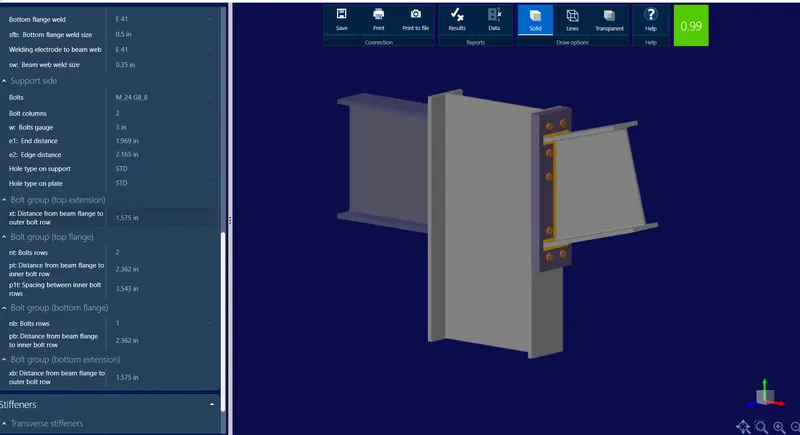
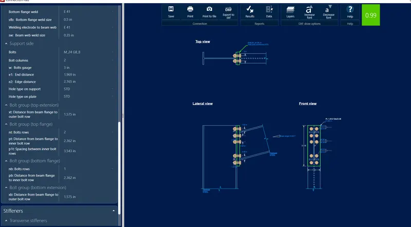
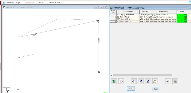
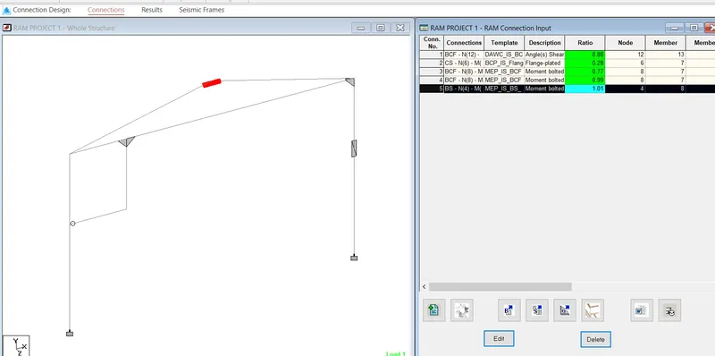
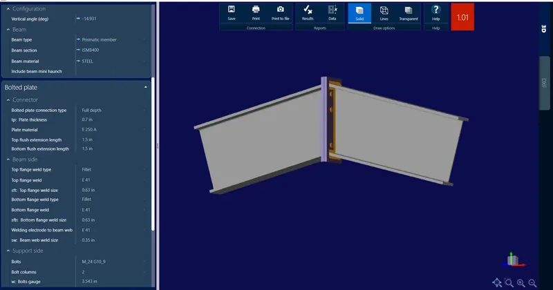
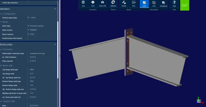
Project 1 - Review of Shear & Moment Connections in RAM Connection
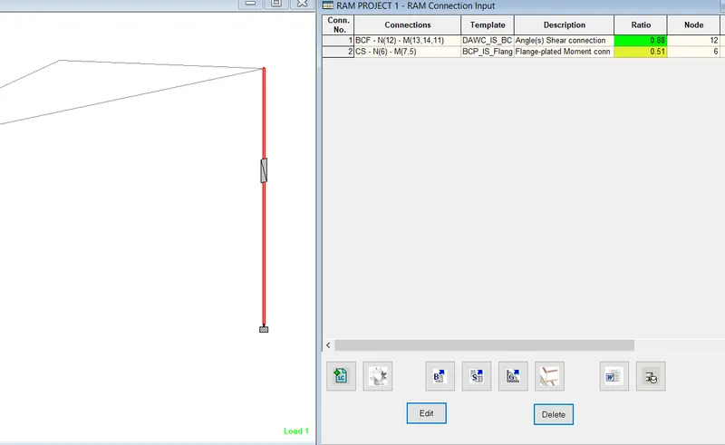
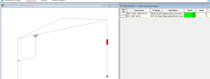
Design and optimize typical shear, moment and Splice joints in RAM Connection for the following structure modelled in Staad Pro. Design and optimize base plate connection.
Structure: A 2D portal frame fixed support spanning 15m with a pitched roof ridge height of 12m, slope of 4 degrees. A uniformly distributed load of 10kN/m is applied on the roof beams. Optimize the beams and columns for 85% utilization and consider splice joints at 6m from base and 4m from beam column joints. Consider a hanger beam shear connected with column support of 4m height from the splice joint with a length of 3m from beam-column corner joint carrying 5kN/m load. Use hot rolled sections.
MODEL
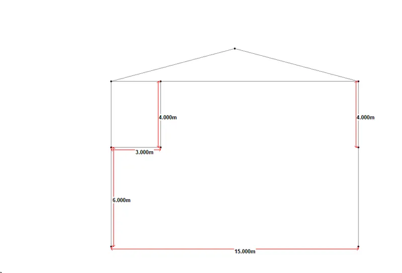
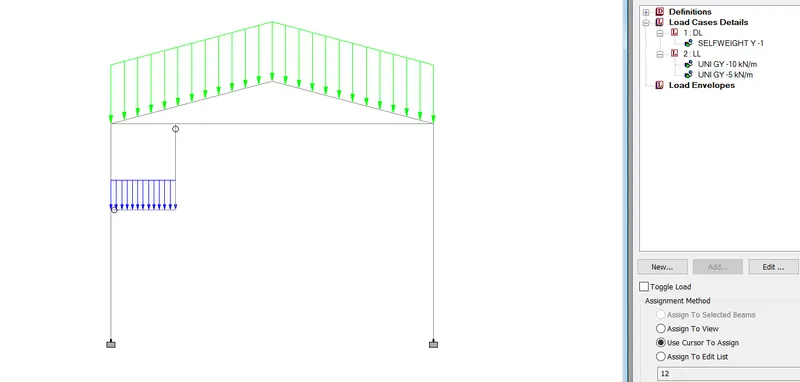
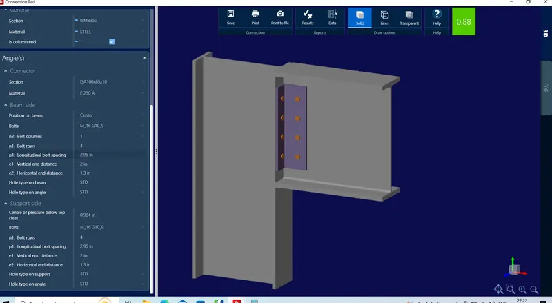
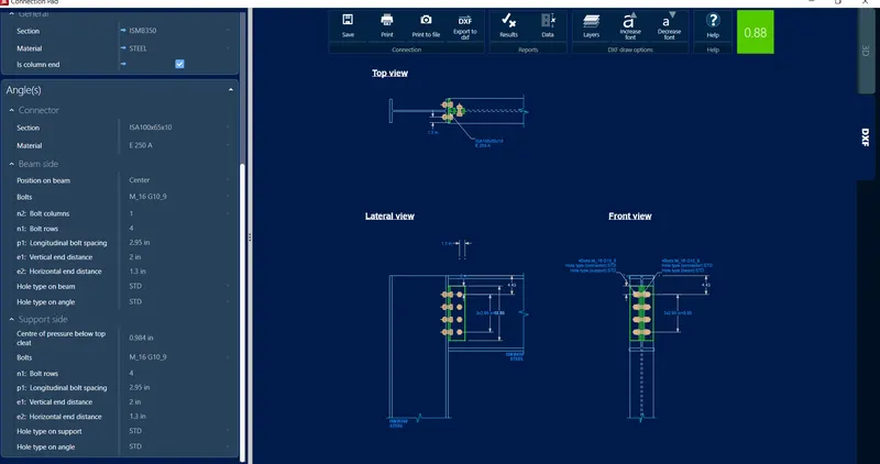
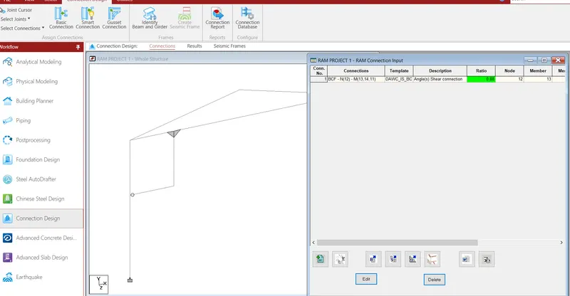
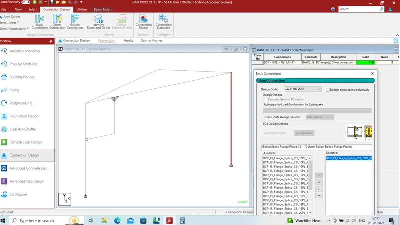
Current Date: 6/21/2023 10:51:16 PM
Units System: kip_in
Design code: IS 800 : 2007
DEMANDS
Description Pu Muin Muout
kip kip*ft kip*ft
LC-1 -3.12 3.10 0.00
LC-2 -17.74 11.78 0.00
LC-3 -31.28 22.32 0.00
LC-4 -20.85 14.88 0.00
GEOMETRIC CONSIDERATIONS
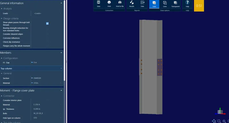
Top column
Dimensions Unit Value Min. Max. Sta. References
Flange cover plate
Bolt diameter [in] 1.18 0.00 - SCI P358 p.185
Front plate
Thickness [in] 0.75 0.68 - Cl. F-2.2, SCI P358 p.185
Length [in] 15.02 14.17 - SCI P358 p.185
Width [in] 7.09 7.09 - Cl. F-2.2
Longitudinal center-to-center spacing (pitch) [in] 3.15 2.95 7.87 Cl. 10.2.3.2
Transverse center-to-center spacing (gage) [in] 2.98 2.95 6.94 Cl. 10.2.3.3
Longitudinal edge distance [in] 2.00 1.95 9.00 Cl. 10.2.4.2, Cl. 10.2.4.3
Transverse edge distance [in] 2.06 1.95 9.00 Cl. 10.2.4.2, Cl. 10.2.4.3
Column
Top flange longitudinal edge distance [in] 2.36 1.95 10.00 Cl. 10.2.4.2, Cl. 10.2.4.3
Bottom flange longitudinal edge distance [in] 2.36 1.95 10.00 Cl. 10.2.4.2, Cl. 10.2.4.3
Top flange longitudinal center-to-center spacing (pitch) [in] 3.15 2.95 7.87 Cl. 10.2.3.2
Bottom flange longitudinal center-to-center spacing (pitch) [in] 3.15 2.95 7.87 Cl. 10.2.3.2
Top flange transverse center-to-center spacing (gage) [in] 2.98 2.95 6.65 Cl. 10.2.3.3
Bottom flange transverse center-to-center spacing (gage) [in] 2.98 2.95 6.65 Cl. 10.2.3.3
Top flange transverse edge distance [in] 2.05 1.95 10.00 Cl. 10.2.4.2, Cl. 10.2.4.3
Bottom flange transverse edge distance [in] 2.05 1.95 10.00 Cl. 10.2.4.2, Cl. 10.2.4.3
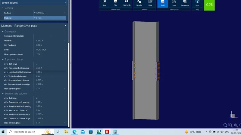
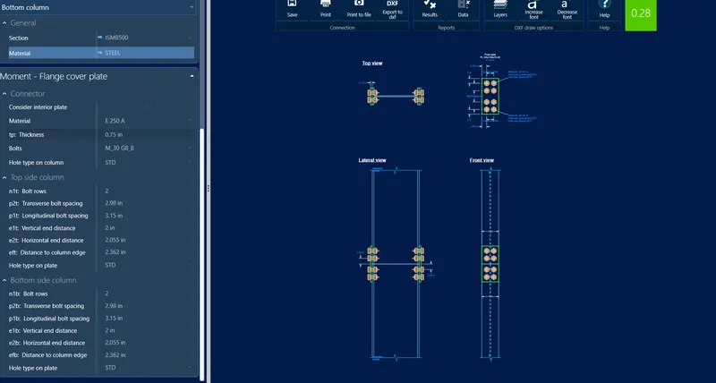
Bottom column
Flange cover plate
Bolt diameter [in] 1.18 0.00 - SCI P358 p.185
Front plate
Thickness [in] 0.75 0.68 - Cl. F-2.2, SCI P358 p.185
Length [in] 15.02 14.17 - SCI P358 p.185
Width [in] 7.09 7.09 - Cl. F-2.2
Longitudinal center-to-center spacing (pitch) [in] 3.15 2.95 7.87 Cl. 10.2.3.2
Transverse center-to-center spacing (gage) [in] 2.98 2.95 6.94 Cl. 10.2.3.3
Longitudinal edge distance [in] 2.00 1.95 9.00 Cl. 10.2.4.2, Cl. 10.2.4.3
Transverse edge distance [in] 2.06 1.95 9.00 Cl. 10.2.4.2, Cl. 10.2.4.3
Column
Top flange longitudinal edge distance [in] 2.36 1.95 10.00 Cl. 10.2.4.2, Cl. 10.2.4.3
Bottom flange longitudinal edge distance [in] 2.36 1.95 10.00 Cl. 10.2.4.2, Cl. 10.2.4.3
Top flange longitudinal center-to-center spacing (pitch) [in] 3.15 2.95 7.87 Cl. 10.2.3.2
Bottom flange longitudinal center-to-center spacing (pitch) [in] 3.15 2.95 7.87 Cl. 10.2.3.2
Top flange transverse center-to-center spacing (gage) [in] 2.98 2.95 6.65 Cl. 10.2.3.3
Bottom flange transverse center-to-center spacing (gage) [in] 2.98 2.95 6.65 Cl. 10.2.3.3
Top flange transverse edge distance [in] 2.05 1.95 10.00 Cl. 10.2.4.2, Cl. 10.2.4.3
Bottom flange transverse edge distance [in] 2.05 1.95 10.00 Cl. 10.2.4.2, Cl. 10.2.4.3
DESIGN CHECK
Top column
Verification Unit Capacity Demand Ctrl EQ Ratio References
Flange cover plate
Bolt group shear [kip] 183.20 22.33 LC-3-2 0.12 Cl. 10.3.3
Front plate
Bolt bearing [kip] 216.24 22.33 LC-3-2 0.10 Cl. 10.3.4
Column
Top flange bolt bearing [kip] 138.10 22.33 LC-3-2 0.16 Cl. 10.3.4
Bottom flange bolt bearing [kip] 138.10 4.88 LC-3-2 0.04 Cl. 10.3.4
Block tearing due to tension (bottom flange) [kip] 136.29 4.88 LC-3-2 0.04 Cl. 6.4.1
Flange plate minimum capacities major axis
Bending [kip*in] 2947.36 826.44 LC-1-0 0.28 Cl. 7.1.2, Cl. 6.2, Cl. 6.3, Cl. 8.2.1.2
Bolt resistance to bending [kip*in] 3743.65 826.44 LC-1-0 0.22 Cl. 10.3.4, Cl. 10.3.3, Cl. 8.2.1.2
Flange plate minimum capacities minor axis
Bending [kip*in] 414.25 60.63 LC-1-0 0.15 Cl. 8.2.1.2
Bolt shear due to bending [kip] 34.52 2.91 LC-1-0 0.08 Cl. 10.3.3, Cl. 10.3.4, Cl. 8.2.1.2
Plate shear [kip] 182.16 9.36 LC-1-0 0.05 Cl. 7.1.2
Bolt shear [kip] 34.52 2.89 LC-1-0 0.08 Cl. 10.3.3, Cl. 10.3.4, Cl. 7.1.2
Bottom column
Flange cover plate
Bolt group shear [kip] 183.20 22.33 LC-3-2 0.12 Cl. 10.3.3
Front plate
Bolt bearing [kip] 216.24 22.33 LC-3-2 0.10 Cl. 10.3.4
Column
Top flange bolt bearing [kip] 138.10 22.33 LC-3-2 0.16 Cl. 10.3.4
Bottom flange bolt bearing [kip] 138.10 4.88 LC-3-2 0.04 Cl. 10.3.4
Block tearing due to tension (bottom flange) [kip] 136.29 4.88 LC-3-2 0.04 Cl. 6.4.1
Flange plate minimum capacities major axis
Bending [kip*in] 2947.36 826.44 LC-1-0 0.28 Cl. 7.1.2, Cl. 6.2, Cl. 6.3, Cl. 8.2.1.2
Bolt resistance to bending [kip*in] 3743.65 826.44 LC-1-0 0.22 Cl. 10.3.4, Cl. 10.3.3, Cl. 8.2.1.2
Flange plate minimum capacities minor axis
Bending [kip*in] 414.25 60.63 LC-1-0 0.15 Cl. 8.2.1.2
Bolt shear due to bending [kip] 34.52 2.91 LC-1-0 0.08 Cl. 10.3.3, Cl. 10.3.4, Cl. 8.2.1.2
Plate shear [kip] 182.16 9.36 LC-1-0 0.05 Cl. 7.1.2
Bolt shear [kip] 34.52 2.89 LC-1-0 0.08 Cl. 10.3.3, Cl. 10.3.4, Cl. 7.1.2
Global critical strength ratio 0.28
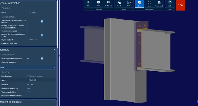
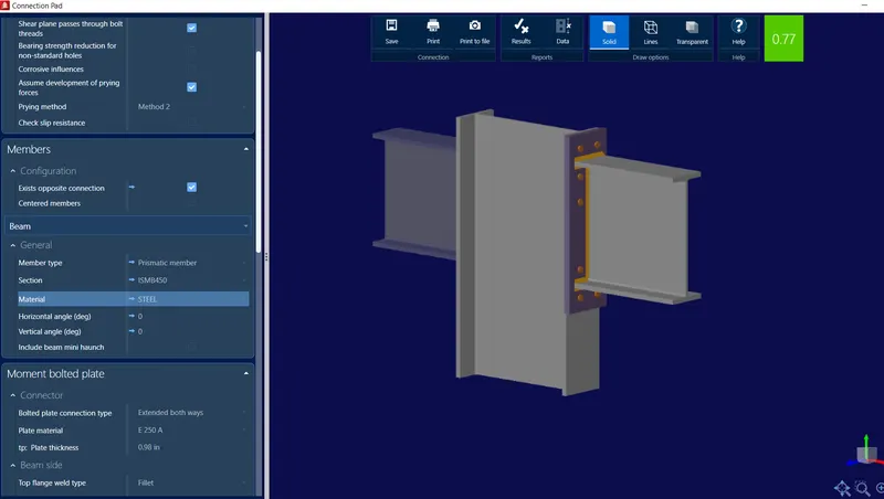
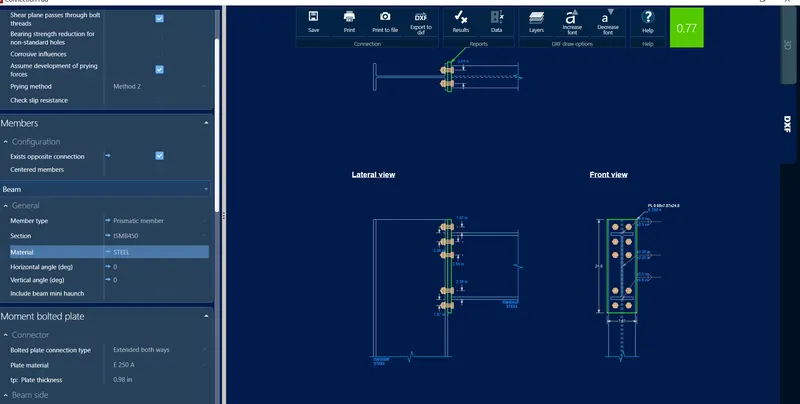
Current Date: 6/21/2023 11:49:46 PM
Units System: kip_in
Design code: IS 800 : 2007
DEMANDS
Description V1 N M1 M2 NfTop NfBottom NfTop NfBottom Vu
kip kip kip*ft kip*ft kip kip kip kip kip
LC-1 -1.27 2.29 -9.45 0.83 7.80 -5.51 -2.11 -0.78 9.49
LC-2 -0.23 30.74 2.44 -34.30 13.65 17.09 9.38 -45.07 15.56
LC-3 -2.25 49.54 -10.51 -50.20 32.17 17.37 10.91 -68.78 18.34
LC-4 -1.50 33.02 -7.00 -33.47 21.45 11.58 7.27 -45.85 12.23
GEOMETRIC CONSIDERATIONS
Dimensions Unit Value Min. Max. Sta. References
Extended end plate
Vertical center-to-center spacing (pitch) [in] 3.54 1.97 7.87 Cl. 10.2.3.2
Horizontal center-to-center spacing (gage) [in] 3.54 1.97 7.87 Cl. 10.2.3.2
Vertical edge distance [in] 1.97 1.30 12.00 Cl. 10.2.4.2, Cl. 10.2.4.3
Horizontal edge distance [in] 2.17 1.30 12.00 Cl. 10.2.4.2, Cl. 10.2.4.3
Top flange weld size [in] 0.50 0.20 0.69
Bottom flange weld size [in] 0.50 0.20 0.69
Web weld size [in] 0.35 0.12 0.37
Support
Vertical center-to-center spacing (pitch) [in] 3.54 1.97 7.87 Cl. 10.2.3.2
Horizontal center-to-center spacing (gage) [in] 3.54 1.97 7.87 Cl. 10.2.3.2
Horizontal edge distance [in] 1.77 1.30 10.00 Cl. 10.2.4.2, Cl. 10.2.4.3
Verification Unit Capacity Demand Ctrl EQ Ratio References
DESIGN CHECK
Moment resistance of joint [kip*in] 1032.65 295.77 LC-3-2 0.29 [EC3-8] Eq.6.25
TENSION ZONE T-STUBS
Row 1
Row 1, alone
Column flange bending [kip] 44.94 [EC3-8] Table 6.2
Column web in transverse tension [kip] 42.08 [EC3-8] Eq.6.15
End plate bending [kip] 57.89 [EC3-8] Table 6.2
Effective resistance [kip] 42.08
Row 2
Row 2, alone
Column flange bending [kip] 47.90 [EC3-8] Table 6.2
Column web in transverse tension [kip] 50.23 [EC3-8] Eq.6.15
End plate bending [kip] 63.46 [EC3-8] Table 6.2
Beam web in tension [kip] 66.10 [EC3-8] Eq.6.22
Row 2, with row 1
Column flange bending [kip] 86.91 [EC3-8] Table 6.2
Column web in transverse tension [kip] 57.75 [EC3-8] Eq.6.15
Effective resistance [kip] 15.67
COMPRESSION ZONE
Column web panel in shear [kip] 99.29 Cl. 8.4.1, Cl. 8.4
Compression zone capacities
Beam bottom flange and web compression resistance [kip] 121.06 5.51 LC-1-0 0.05 [EC3-8] Eq.6.21
Web panel in shear [kip] 99.29 18.34 LC-3-2 0.18 Cl. 8.4.1, Cl. 8.4
Column web compression at beam bottom flange [kip] 59.24 5.51 LC-1-0 0.09 [EC3-8] Eq.6.9
Vertical shear resistance of bolt group [kip] 144.93 2.25 LC-3-2 0.02 Cl. 10.3.3, Cl. 10.3.4, [2]
Web fillet weld shear resistance [ksi] 19.43 3.24 LC-3-2 0.17 Cl. 10.5.7.1.1, Cl. 10.5.10.1.1
Top fillet weld transverse force resistance [ksi] 19.43 14.88 LC-1-0 0.77 Cl. 10.5.7.1.1
Bottom fillet weld transverse force resistance [ksi] 19.43 13.97 LC-2-1 0.72 Cl. 10.5.7.1.1
Global critical strength ratio 0.77