Powertrain for aircraft in runways
AIM:
To calculate the push/pull force and power required for the vehicle that tows Aircrafts in runways and design an appropriate powertrain.
The following points have to be addressed:
- Search and list out the total weight of various types of aircrafts.
- Is there any difference between ground speed and air speed?
- Why is it not recommended to use aircraft engine power to move it on the ground at Airport?
- How an aircraft is pushed to runway when its ready to take off?
- Learn about take-off power, tire design, rolling resistance, tire pressure, brake forces when landing.
- With necessary assumptions, calculate the force and power required to push / pull an aircraft by a towing vehicle.
- Design an electric powertrain with type of motor, it’s power rating, and energy requirement to fulfill aircraft towing application. Estimate the duty cycle range to control the aircraft speed from zero to highest. Make all required assumptions. Prepare a table of assumed parameters. Draw a block diagram of powertrain.
SOLUTION:
1.Search and list out the total weight of various types of aircrafts.
The primary factors that categorize the different types of aircraft are ‘Heavier-Than-Air’ (Aerodyne) and ‘Lighter-Than-Air’ (Aerostat) aircraft.
The next level of classifying is powered and unpowered aircraft. From this point, aircraft designs, technology, and capabilities differ in many different aspects and categories.
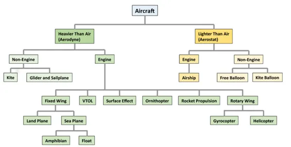
Weights of different aircrafts
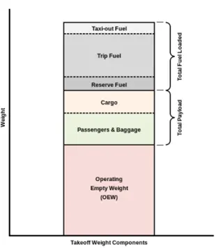
These are the typical values of weights (in tons) for different types of aircrafts
Type of Aircraft Weight (tons)
Commercial Aircrafts: 500-600
Business Jets 7-15
Single Engine Piston 5-10
Tricycle Gear 5-10
Taildraggers 5-10
Helicoptors 5-22
Seaplanes 5-10
Airship/Zeplins 5-10
2.Is there any difference between ground speed and air speed?
Ground speed is the airplane’s speed relative to the surface of the Earth. It is horizontal rather than vertical speed. Which means that, an aircraft climbing completely vertically would have a ground speed of zero.
Airspeed is its speed relative to the air it is flying in. It can also be called as the speed at which the air is flowing around the aircraft’s wings.
If we compare a ground vehicle such as a car moving in one direction with a speed of x kmph and an aircraft flying at x kmph without any wind, then both will have the same Ground speed. Whereas, if the aircraft experiences wind in the direction of its flight, i.e. it experiences tailwind, then its speed will be x kmph + the wind speed. In this case, the aircraft will be moving faster than the car on ground. Thus, having greater ground speed.
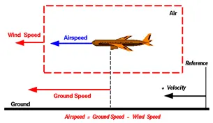
On the other hand, if the wind is blowing against the direction the aircraft is traveling in, the aircraft experiences headwind, and its ground speed is lower than its airspeed. Thus, we can say that the ground speed is the vector addition of the wind speed and the airspeed.
For tailwind, Airspeed = Ground Speed - Wind Speed
For headwind, Airspeed = Ground Speed + Wind Speed
Other than that, when crosswinds blow, the airspeed & ground speed have to be calculated accordingly by vector additions.
3.Why is it not recommended to use aircraft engine power to move it on the ground at Airport? & 4. How an aircraft is pushed to runway when its ready to take off?
Controlling an aircraft in the air is important, but being able to steer it accurately on the ground is equally so.
Taxiing: It refers to an aircraft’s movement while on the ground, under its own power. This term excludes the accelerating run along a runway before takeoff and the decelerating run immediately upon landing.
◦ By using jet engines as an aircraft’s primary thrust for taxiing, airlines spend huge amounts of jet fuel while still on the ground, which could be much better used for flying. Many airlines plan to adopt electric taxiing (within the aircraft) to save fuel and reduce environmental impacts.
◦ Even when reversing the aircraft, jet reversers blows debris creating foreign object damage hazard for adjacent aircraft, gate equipment or terminal waiting area glass windows and can also damage the crowded gate area.
◦ This is accompanied with the high noise that the engine produces.
◦ The engine produces large thrust from the exit and vacuum from the front which may suck in objects which may damage the engine.
Thus, it is not recommended to use the aircraft engine power to move the aircraft on the ground.
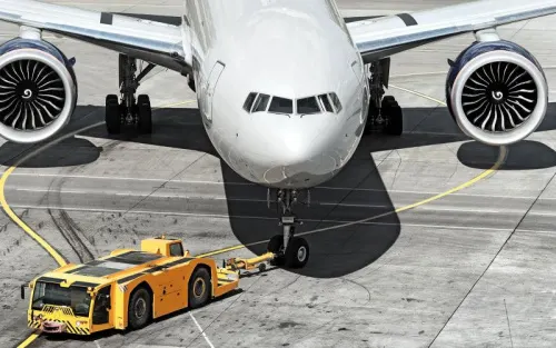
◦ Special Towing vehicles are thus used by many airlines usually only for pushbacks for the above mentioned reasons. Pushback is an airport procedure during which an aircraft is pushed backwards away from an airport gate/terminal by external power. A motorized vehicle called a tug is used to push the aircraft back from its gate. The towing vehicle driver also has more knowledge about the roads within the airport and can have a better view of the way than the pilot sitting in the cockpit. The aircraft generally moves under its own power along the taxiways to get to the runway.
◦ Towing may also be needed for the movement of active or disabled aircraft on airport ramps or in moving aircraft in and out of hangers for maintenance procedures or for storage
5. Learn about take-off power, tire design, rolling resistance, tire pressure, brake forces when landing.
Takeoff is the phase where the aircraft will go from the taxiing to flying. Thus the power at the end of the ground run will be the takeoff power of the aircraft.
The forces acting on the airplane are shown in the figure below. The forces acting on the airplane are the ground reaction (R) and weight of the aircraft(W). The rolling friction: μR (μ is the coefficient of rolling friction between the runway and the landing gear wheels) which will act against the motion of the plane. The lift(L) and forward motion(T) will be produced by the thrust of the turbine. When in motion, the aerodynamic drag(D) will act.
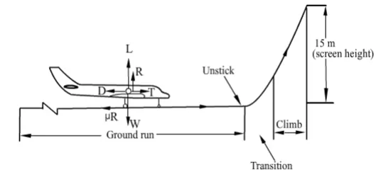
The equations of motion during the ground run will be given by:
T - D - F = m*a
Where, m is the mass of the vehicle (Weight(W)/gravitational acceleration(g))
a is the effective acceleration of the aircraft.
T is the thrust generated by the turbine
D is the aerodynamic Drag given by:
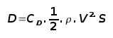
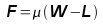
R is the normal reaction which will be equal to the difference of the weight of the aircraft and the lift produced.
F = μR will be the rolling resistance friction given by:
The takeoff power can be calculated by the equation:
Power = Force * Velocity
= (T-D-F)*V
This velocity V of the aircraft at the time of takeoff (it is calculated meticulously by considering various aircraft dynamics) Ideally, this velocity should be greater than the Vstall which is the minimum velocity required so that the aircraft can be flown before the airflow starts to separate from wings as the angle of attack becomes too great. For safety reasons, V is taken to be 1.2*Vstall.
Braking forces during landing
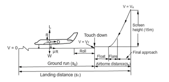
The flight speed at the point of touch down is denoted by VT . It is about 90% of VA . After the touch down, the airplane rolls for a period of about 3 seconds during which the nose wheel is gently lowered to touch the ground. Brakes are not applied in this phase as their application would produce a large decelerating force which would cause a large nose down moment and the nose wheel may hit the ground with a bang. After the three wheels have touched the ground, the brakes are applied as well as other devices like reverse thrust or reversed pitch of propeller are deployed. The ground run is said to be over when the airplane comes to halt or attains a low speed when it can turn off the runway and go to the parking place.
Here, the braking Force will be the reverse thrust by the engine and the equations of motion can again be written as
- T - D - F = m*a
Where the symbols have their usual meaning.
Thus breaking forces can then be calculated in a similar way that take-off was calculated.
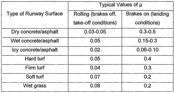
The Rolling resistance friction is the opposing force that’s comes into play because of the interaction between the tires of a vehicle and the surface on which it runs. The Airport Runways and tires of the aircraft are specially designed so that to keep this opposing to a minimum to maximize the fuel economy.
Friction is expressed as the coefficient of friction; this is the ratio of the friction force (F) between two surfaces in contact and the normal force (N) which exists between the object resting on the surface and the surface i.e. F/N. This ratio is particularly, but not exclusively dependent, upon:
- The physical characteristics of the two surfaces.
- The prevailing temperature at the point of contact.
- The speed of movement of the object (the tyre) over the surface.
- Contaminant (moisture etc.)
The degree of surface friction for a specific aircraft at a given moment is directly proportional to the braking action, subject only to the activation of wheel lock-up and anti-skid protection systems, which most modern transport aircraft have.
The typical values for the coefficient of rolling friction for the runway surface are:
Tyre Design
Aircraft tyres are designed to withstand extremely heavy loads for short durations, with the number of tyres required increasing with the weight of the plane in order to better distribute the weight.
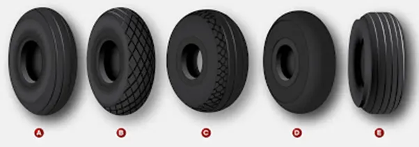
Aircraft tyre tread patterns are designed to facilitate stability in high crosswind conditions, to channel water away to prevent aquaplaning, and for braking effect. Some types of nose wheel tyres include one (or two) chine moulded into the rubber on the shoulder buttresses that deflects water away during aircraft movement on a wet runway. Aircraft tyres also include heat fuses (sometimes called fusible plugs) which are designed to melt at a certain temperature in order to reduce the risk of an explosive deflation due to overheating.
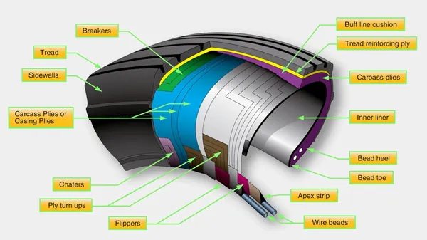
Tire Construction with its major components:
Bead
The tire bead is an important part of an aircraft tire. It anchors the tire carcass and provides a dimensioned, firm mounting surface for the tire on the wheel rim
An apex strip is additional rubber formed around the bead to give a contour for anchoring the ply turn-ups. Layers of fabric and rubber called flippers are placed around the beads to insulate the carcass from the beads and improve tire durability. Chafers are also used in this area. The chafers protect the carcass from damage during mounting and demounting of the tire. They also help reduce the effects of wear and chafing between the wheel rim and the tire bead especially during dynamic operations.
Carcass Plies
Carcass plies, or casing plies as they are sometimes called, are used to form the tire. Each ply consists of fabric, usually nylon, sandwiched between two layers of rubber. The plies are applied in layers to give the tire strength and form the carcass body of the tire. The reinforcing plies and protector plies help resist puncture and cutting while protecting the carcass body of the tire.
Tread
The tread is the crown area of the tire designed to come in contact with the ground. It is a rubber compound formulated to resist wear, abrasion, cutting, and cracking. It also is made to resist heat build-up. Most modern aircraft tire tread is formed with circumferential grooves that create tire ribs. The grooves provide cooling and help channel water from under the tire in wet conditions to increase adhesion to the ground surface. Tires designed for aircraft frequently operated from unpaved surfaces may have some type of cross-tread pattern. Older aircraft without brakes or brakes designed only to aid in taxi may not have any grooves in the tread. An all-weather tread may be found on some aircraft tires.
Sidewall
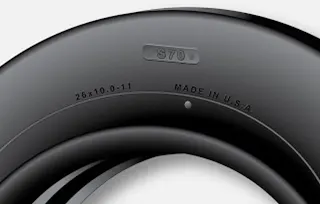
The sidewall of an aircraft tire is a layer of rubber designed to protect the carcass plies. It may contain compounds designed to resist the negative effects of ozone on the tire. It also is the area where information about the tire is contained. The tire sidewall imparts little strength to the cord body. Its main function is protection.
Chine
Some tire sidewalls are mounded to form a chine. A chine is a special built-in deflector used on nose wheels of certain aircraft, usually those with fuselage mounted engines. The chine diverts runway water to the side and away from the intake of the engines. Tires with a chine on both sidewalls are produced for aircraft with a single nose wheel. The chine construction can be observed in the (E) type tread figure mentioned above.
Tire Pressure
The pressure of an aircraft tire severely affects its safety. Aircraft tires generally operate at high pressures of around 200psi. To prevent one tyre on a gear from carrying extra load, all tyres on a single gear should be inflated equally. The mate tyre(s) will share the load, allowing individual tyres to run underinflated or overloaded if pressures are unequal, because all tyres on the gear will deflect identically. The tire pressure changes with the temperature. A temperature change of 3°C produces approximately 1% pressure change. There are other factors that are responsible for the change in pressure.
Low pressures add to the rolling resistance force and thus more power is required to overcome the same distance. Thus, pressure should be maintained at the calculated value. Nitrogen should be used for tyre inflation as it will not sustain combustion and will reduce degradation of the liner material, casing plies and wheel due to oxidation.
6. With necessary assumptions, calculate the force and power required to push / pull an aircraft by a towing vehicle.
For this question, the Towing vehicle considered is KAMBLAR Tow tractor TBL 190 and the aircraft considered is Airbus A319
TBL 190 is designed for pushback and maintenance towing of aircraft from MD-80/A319 up to B777/A340.
Length: 8,100 mm
Width: 3,450 mm
Height: 2,050 mm
Thus, frontal area is calculated to be: 7.07m2
Dry weight: 15,150 kg
Working speed: 23 km/h, 30 km/h (14.3 mph)
The Airbus A319 has the following specifications:
Length 33.8m
Wingspan 35.8m
Height 11.8m
Maximum take-off weight 64,000 – 75,500 kg
Weight of Aircraft 35,400 kg
Drag Coefficients (Cd): Taxing: 0.031
Take-off: 0.024
Landing: 0.017
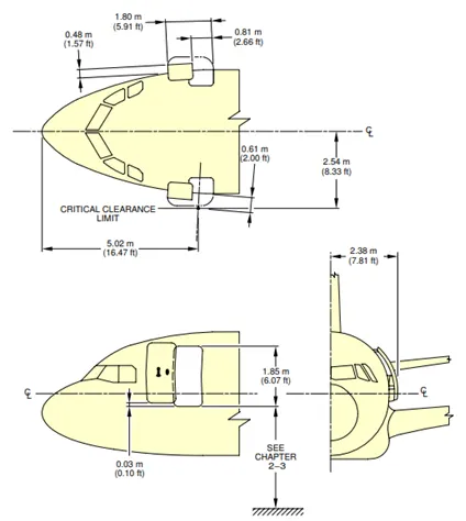
The frontal area for the Airbus A319 can estimated as
Area = (Width)*(Height)
= (2*2.54)*(2*2.38)
= 24.18m2
The area of the wings can be estimated to be
Area = Width*Height
(35.08-(2*2.54))*(0.3)
=30.72*0.3
=9.2118m2
Hence, the total frontal area to be considered for the aircraft and tow truck will be
=Frontal Area of tow truck + Frontal Area of Aircraft
= Frontal Area of tow truck + (Frontal Area of Wings + Frontal Area of cabin)
= 7.07 + 9.2118 + 24.18
=40.46m2
The forces to be taken into consideration while calculating the traction power required are
- Frr = μrr mg
Where, Frr is the Rolling Resistance Force in N
μrr is the Coefficient of Rolling Resistance
m is the total mass of vehicle in kg
g (g=9.81) is the acceleration due to gravity in m/s2
- Fad =
Where, Fad is the Aerodynamic Drag Force in N
is the Air Density
A is the Frontal Area of vehicle in m2
Cd is the Drag Coefficient
V2 is the velocity in m/s
- Fh = mg sin(Ψ)
Where, Fh is the Hill Climbing Force in N
Ψ is the Hill Climbing Angle in radian
- Fa = ma
Where a is the acceleration of the vehicle in m/s2
The summation of all the forces multiplied by the vehicle velocity will give the required power.
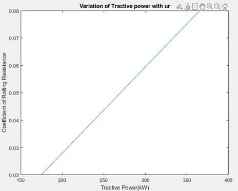
The following m script is used for calculating the required power. The acceleration force is neglected here. Tractive power requirement with changing μrr is plotted
clc

m = 50550;                                      %Mass of tow tractor & Aricraft
g = 9.81;                                       %Acceleration due to gravity
ur = linspace(0.02,0.08,7);                     %Coefficient of rolling resistance for different surfaces
rho = 1.25;                                     %Air Density
A = 40.46;                                      %Assumed Frontal Area of tow truck & Aircraft
Cd = 0.03;                                      %Aerodynamic drag coefficent
v = 6.4;                                        %Velocity in m/s
slope = 0.035;                                  %Assumed Hill climbing angle 2deg
Ft = [];                                        %Array to store total calculated force

for i=1:length(ur)
    Fr = ur(i)*m*g;
    Fd = 0.5*rho*A*Cd*(v^2);
    Fh = m*g*sin(slope);
    Ft(i) = Fr + Fd + Fh;
end

power = (Ft*v)/1000                             %Power in kW(=Force*velocity)
%PLOT
plot(power,ur)
xlabel('Tractive Power(kW)')
ylabel('Coefficient of Rolling Resistance')
title('Variation of Tractive power with ur')

The torque required can also be calculated if the wheel radius and gear ratio of the towing vehicle are known by using the formula
Torque = Force*radius/Gear Ratio
7.Design an electric powertrain with type of motor, it’s power rating, and energy requirement to fulfill aircraft towing application. Estimate the duty cycle range to control the aircraft speed from zero to highest. Make all required assumptions. Prepare a table of assumed parameters. Draw a block diagram of powertrain.
The power calculated in the above example is 174.73 kW for the rolling resistance coefficient of 0.02. The same is considered for the further calculation.
Since 1kWh = 1.34HP
174.73kW will be equivalent to approximately 235HP. Hence, the motor should have a rating of 235 HP
The Vascat 175kW (235HP) x 3200RPM/6000RPM AC Vector Motor IP23 B3 160X might be suitable.
Energy required for towing = Power * Time
= 174.73kW * 10min
= 29.12 kWh
Thus, the battery for the towing vehicle should be able to supply a minimum of 30kWh of energy for one successful towing cycle of 10mins. The C-Rate for the battery should be very high. The Nissan Leaf uses a battery of 30kWh but the discharge rate is significantly lower than what will be required for this application.
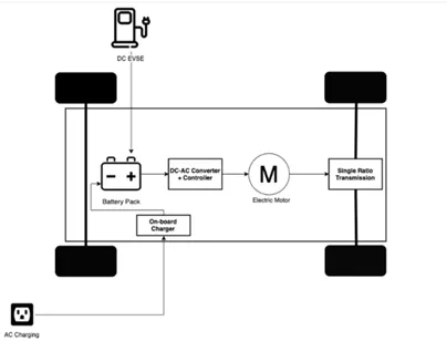
The typical powertrain block diagram for the aircraft towing vehicle will be as shown below. The battery will store DC power and the On-board Charger will convert the AC supply into a DC supply so that the battery can be charged. Further, due to ease to control the speed and torque, an AC Induction motor (IM) with vector control is used. Thus the DC power stored in the battery has to be converted into AC power by use of an Inverter circuit arrangement as shown in the figure.
CONCLUSION:
Taxing & Pushback of Aircrafts using the turbine power is undesirable. Towing vehicles prove as a better alternative for that purpose. The power and energy requirements for a towing vehicle were calculated and a simple pure electric drivetrain for the same is presented.