Project-1: Powertrain for aircraft in runways
AIM: To Design an electric powertrain with type of motor its power rating and energy requirement to fulfill aircraft towing application.
Objective:
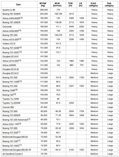
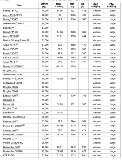
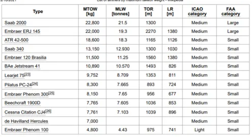
- Search and list out the total weight of various types of aircrafts.
- Is there any difference between ground speed and air speed?
- Why is it not recommended to use aircraft engine power to move it on the ground at Airport?
- How an aircraft is pushed to runway when its ready to take off?
- Learn about take-off power, tyre design, rolling resistance, tyre pressure, brake forces when landing.
- With necessary assumptions, calculate the force and power required to push / pull an aircraft by a towing vehicle.
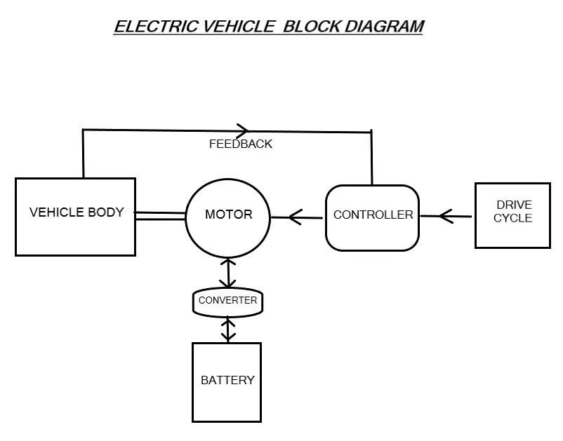
- Design an electric powertrain with type of motor, it’s power rating, and energy requirement to fulfil aircraft towing application. Estimate the duty cycle range to control the aircraft speed from zero to highest. Make all required assumptions. Prepare a table of assumed parameters. Draw a block diagram of powertrain.
Introduction to Powertrain:
POWERTRAIN:
The Power train is a musculature system which consists of power source(engine) and all of the components that converts the engine power into movement of the vehicle. Most of the engines are Internal combustion engines, electric vehicles and some of the vehicles consists of both which are called Hybrid Electric Vehicles (HEV). The types of Internal combustion engines are Petrol engines, Diesel engines, Ethanol engines, Liquefied petroleum gas. The types of pure electrical vehicles consist of, they use batteries for energy storage called as battery electric vehicles.
Difference Between Powertrain in EV vehicles and ICE vehicles:
When Compared to ICE vehicles, the EV vehicles powertrain have less components and occupies less space.
Powertrain in Internal Combustion Engine vehicles:
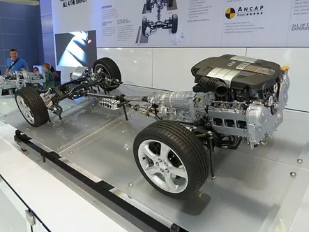
(i) Drivetrain: The drivetrain is the group of components between the engine and the and the wheels that produce, develop or assist drive to make the complete drivetrain. Drivetrains for front, rear and all-wheel drive and four-wheel drive vehicles are all quite different due to the need to send the engine's power out to the wheels in different ways. The drivetrain consists of the transmission, driveshafts, differential and axles.
(ii) Transmission: The transmission is the gearbox and clutch, which transmits and converts power from the engine into twist (rotational force) for the wheels. The clutch engages or disconnects the turning engine from the gears as they are shifted up, down, or into neutral. Without the clutch, the engine’s rotation locked to the gear would wind down to a shuddering halt, and stall. Gears are the way of best harnessing and optimising the engine’s power no matter at what speed the vehicles are travelling. A low gear (first or second) produces more force at lower speeds i.e., to get the vehicle off the line, while a high gear produces less force at higher speeds to keep the vehicle rolling along rapidly.
(iii) Driveshaft: The driveshaft is also called a propeller shaft. This is a long rotating shaft that runs all the way down the centre of the vehicle bridging the gap between the engine/transmission and the wheels by sending twist to the waiting rubber. Front-engine, front wheel drive cars don’t need to send power down the line like this; instead they compact the transmission and differential into one unit, called a transaxle.
(iv) Differential: The differential allows the driven wheels to rotate at different speeds by increasing the grip. Without a differential, the driven wheels would be locked together and forced to spin at the same speed. When we are driving on the straight road it won't create any problem, but on corners particularly when they are tight, it would leave one wheel spinning uselessly. This helps to split the power out into the two wheels.
(v) Axles: A wheel is connected to the axle. When the axle rotates, the wheel which is connected or driven to it gives a direction of motion. The axle is the shaft on which a wheel or a gear rotates.
Powertrain in Electric Vehicle vehicles:
An EV powertrain has 60% fewer components than the powertrain of an ICE vehicle. Which is described below
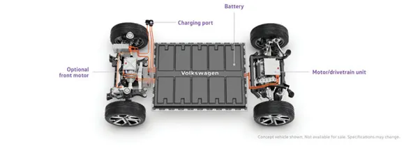
Battery Pack: The battery pack is made up of multiple Lithium-ion cells and stores the energy needed to run the vehicle. The battery pack provides direct current (DC) output.
DC - AC Converters: The DC Supplied by the battery pack is converted to AC and supplied to the electric motor. This power transfer is managed by a sophisticated motor control mechanism that controls the frequency and magnitude of the voltage supplied to the electric motor in order to manage the speed and acceleration as per the driver's instructions communicated via acceleration/brakes.
Electric Motor: It converts electrical energy to mechanical energy that is delivered to the wheels via single ratio transmission. Many EVs use a motor-generator that can perform regeneration as well.
On-board charger: It converts AC received through charge port to DC and controls the amount of current flowing into the battery pack.
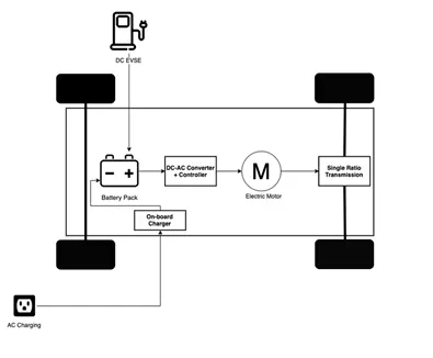
Apart from the above core parts, there are multiple hardware and software components in an EV powertrain. Electronic Control Units (ECUs) are basically software programs integrated with the powertrain components to help data exchange and processing. There are several small ECUs in an EV that perform specific functions. The communication between different ECUs in a vehicle is commonly carried over CAN Protocol. More examples of core ECUs are:
Battery Management System (BMS): A BMS continuously monitors the state of the battery and is responsible for taking necessary measures in case of a malfunction. BMS performs cell balancing to deliver maximum efficiency from the battery pack. It is responsible for communication with other ECUs and sensors as well as EVSEs to control the charging input, to check the current stage of charge and share data about battery specifications.
DC-DC Converter: A battery pack delivers a fixed voltage, but the requirement of different accessory systems (e.g wipers, lights, infotainment system, mirror control) in the EV would vary. The DC-DC converter helps distribute power to different systems by converting the output power from the battery pack to the expected level. After conversion, power is delivered to respective smaller ECUs via a wiring harness.
Thermal Management System: Responsible for maintaining optimum operating temperature range for powertrain components.
Body Control Module (BCM): The BCM is responsible for supervising and controlling the functions of electronic accessories such as power windows, mirrors, security, and vehicle access control.
1. Search and list out the total weight of various types of aircrafts.
Aircraft:
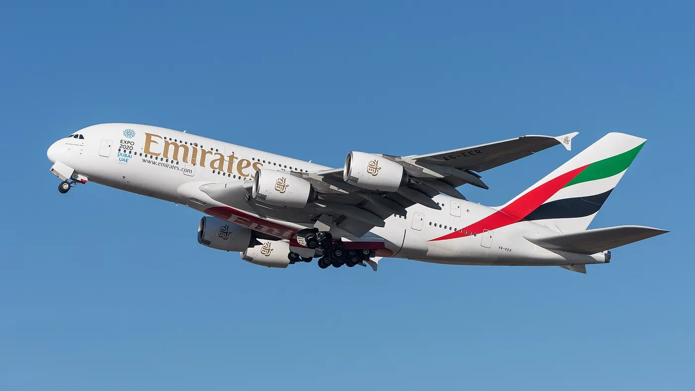
An aircraft is a vehicle that is able to fly by gaining support from the air. It counters the force of gravity by using either static lift or by using the dynamic lift of an airfoil, or in a few cases the downward thrust from jet engines. Common examples of aircraft include airplanes, helicopters, airships (including blimps), gliders, paramotors and hot air balloons.
The different terms represent different weights or masses. For each flight, the weights are taken into account for several reasons.
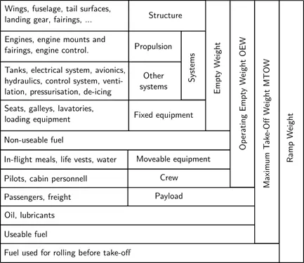
Manufacturer's empty weight (MEW):
It is also called Manufacturer's Weight Empty (MWE) or Licensed Empty Weight. It is the weight of the aircraft "as built" and includes the weight of the structure, power plant, furnishings, installations, systems and other equipment that are considered an integral part of an aircraft. This excludes any baggage, passengers, or usable fuel2.
Zero-fuel weight (ZFW): This is the total weight of the airplane and all its contents (including unusable fuel), but excluding the total weight of the usable fuel on board. As a flight progresses and fuel is consumed, the total weight of the airplane reduces, but the ZFW remains constant. Maximum zero fuel weight (MZFW) is the maximum weight allowed before usable fuel and other specified usable agents (engine injection fluid, and other consumable propulsion agents) are loaded.
Usable fuel: Usable fuel is the fuel on board an aircraft that can actually be used by its engines.
Unusable fuel: The small amount of fuel that cannot be drained from the tanks is the Unusable fuel.
Operating empty weight (OEW): (Roughly equivalent to basic empty weight on light aircraft)
It is the basic weight of an aircraft including the crew, all fluids necessary for operation such as engine oil, engine coolant, water, unusable fuel and all operator items and equipment required for flight but excluding usable fuel and the payload.
Payload: It is the carrying capacity of an aircraft. It includes cargo, people, extra fuel. In the case of a commercial airliner, it may refer only to revenue-generating cargo or paying passengers.
Maximum take-off weight (MTOW): This is the maximum weight at which the pilot of the aircraft is allowed to attempt to take off3.
Regulated take-off weight (RTOW): Depending on different factors (e.g., flap setting, altitude, air temperature, length of runway), RTOW or maximum permissible take-off weight varies for each take-off. It can never be higher than MTOW. More information is on this answer.
Maximum landing weight (MLW): This maximum weight at which an aircraft is permitted to land3.
Maximum ramp weight (MRW): It is also called as maximum taxi weight (MTW). It is the maximum weight authorized for manoeuvring (taxiing or towing) an aircraft on the ground.
Aircraft gross weight: It is the total aircraft weight at any moment during the flight or ground operation. This decreases during flight due to fuel and oil consumption.
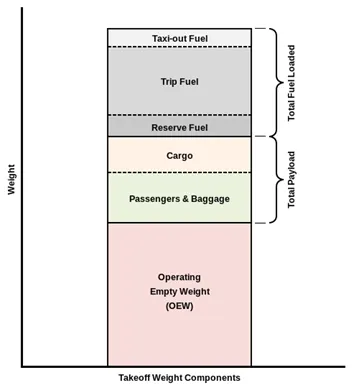
The following image depicts take-off weight components.
The below diagram is the Example how to determine the Aircraft weight.
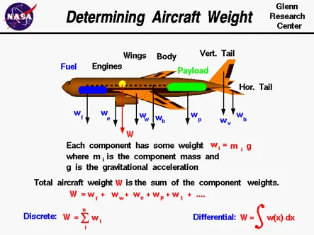
|
The below image explains the takeoff weight components. |
The generalised explanation of the each weight in the Table form. |
|
|
|
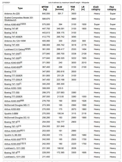
Types of Aircrafts:
- MTOW = Maximum take-off weight,
- MLW = Maximum landing weight,
- TOR = Take-off run (SL,ISA+15°, MTOW),
- LR = Landing run (SL, ISA+15°, MLW)
2. Is there any difference between ground speed and air speed?
Ground Speed:
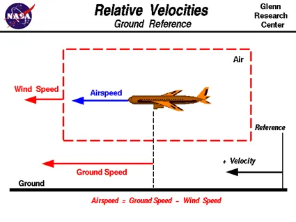
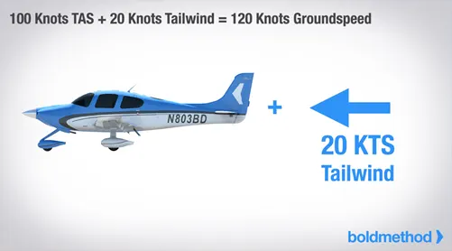
The movement of your airplane relative to the ground is called groundspeed. Ground speed is based on the aircraft's travelling speed relative to a fixed point on the ground. It is a vector quantity relative to the wind speed It's true airspeed corrected for wind. With a true airspeed of 100 knots and a tailwind of 20 knots, you'd be flying a groundspeed of 120 knots.
If you shot a police radar gun at a plane flying by, you'd be measuring groundspeed of the airplane, assuming the officer was stationary.
Airspeed:
The airspeed is defined as the relative velocity between the object and the air in the generation of lift. Airspeed cannot be directly measured from a ground position; it must be calculated from the ground speed and the wind speed. Airspeed is the vector difference between the ground speed and the wind speed.
Airspeed = Ground Speed - Wind Speed
The airspeed is equal to the ground speed. But if the wind is blowing in the same direction that the aircraft is moving, the airspeed will be less than the ground speed. Airspeed is how fast an airplane is really flying strictly under its own power, which is calculated by subtracting the wind speed from the ground speed. Airspeed not only affect airplanes; it also affects the vehicles on the ground.
They are four types of Air speed,
Airspeed is more than simply reading off your airspeed indicator. Here are the 4 types of airspeed, and what each means for your flying...
(i) Indicated Air Speed:
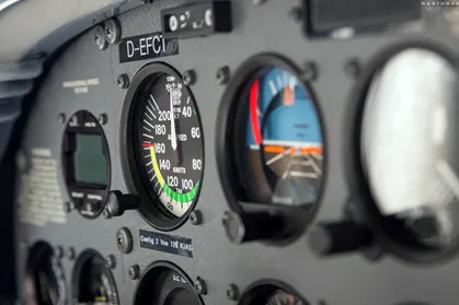
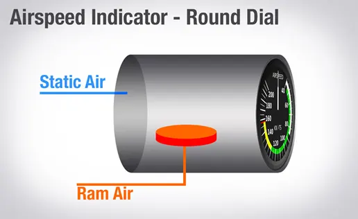
It's read right off your air speed indicator and is usually what you'll reference in the cockpit for speed changes. The speed limits of the sky, like not exceeding 250 knots below 10,000 feet MSL, are all written as indicated airspeed values.
(ii) True Air Speed (TAS):
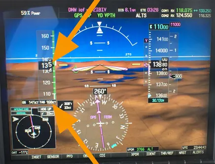
True airspeed is the speed of your aircraft relative to the air it's flying through. As you climb, true airspeed is higher than your indicated airspeed. Pressure decreases with higher altitudes, so for any given true airspeed, as you climb, fewer and fewer air molecules will enter the pitot tube. Because of that, indicated airspeed will be less than true airspeed. In fact, for every thousand feet above sea level, true airspeed is about 2% higher than indicated airspeed. So, at 10,000 feet, true airspeed is roughly 20% faster than what you read off your airspeed indicator. Many aircraft, such as those with gas turbine engines, can reach a higher TAS at higher altitudes because their engines are more efficient at higher altitudes.
(iv) Calibrated Air Speed (CAS):
Calibrated airspeed is indicated airspeed corrected for instrument and positional errors. At certain airspeeds and with certain flap settings, the installation and instrument errors may total several knots. This error is generally greatest at low airspeeds, with nose high pitch attitudes. When flying at sea level under International Standard Atmosphere (ISA) conditions (15 degrees Celsius, 29.92 inches of mercury, 0% humidity), calibrated airspeed is the same as true airspeed. If there is no wind it is also the same as ground speed.
3. Why is it not recommended to use aircraft engine power to move it on the ground at Airport?
It is not recommended to use aircraft engine power to move it on the ground at airport because there are some certain cautions which cause the life-threatening hazards to the humans and damage to the aircraft. Here are some cautions if we use aircraft engine on the ground at Airport
- High engine thrust during maintenance activity can cause considerable damage to airplanes and other elements in the airport environment.
- While starting the engine of the aircraft, it releases more amount of power and harmful gases which cause the melting of objects. People, equipment and anything else in the way can be injured or damaged from the jet blast.
- Before starting the engine of the aircraft, the surroundings should be carefully observed especially the areas in front of each engine are like another super critical factor that must be carefully negotiated.
- The immediate area in front of a jet engine creates an area where people and equipment can be sucked in to the engine if anything is too close to the intake.
- So to avoid all such extreme cautions it is not recommended to use aircraft engine power to move it on the ground at the airport.
4. How an aircraft is pushed to runway when its ready to take off?
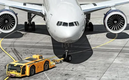
An aircraft is pushed to runway by means of Procedure called Pushback when is ready to take off.
- Pushback is an airport procedure during which an aircraft is pushed backwards away from an airport gate by pushback or tugs.
- Pushback takes place at the aerodromes where they are placed at the ground control clearance to facilitate ground movement on pathway connecting runways, with aprons, hangars, terminals and other facilities.
- Once clearance is obtained, the pilot will communicate with the tractor driver (or a ground handler walking alongside the aircraft in some cases) to start the pushback.
- Since the pilots cannot see what is behind the aircraft, steering is done by the pushback tractor driver and not by the pilots.
- Depending on the aircraft type and airline procedure, a bypass pin may be temporarily installed into the nose gear to disconnect it from the aircraft's normal steering mechanism.
- Once the pushback is completed, the towbar is disconnected, and any bypass pin removed.
- The ground handler will show the bypass pin to the pilots to make it clear that it has been removed. The pushback is then complete, and the aircraft can taxi forward under its own power.
Need of Pushback:
- when the aircraft itself started to use reverse thrust to Pushback, air blast fom engines would stir up surrounding debris and no no-one should be near the plane when it is starting.
- The tugs are used to push back the aircraft whatever the direction of the aircraft should be placed on the runway.
- The aircraft sucks the items into the engine because, when the aircraft started the engine's propellers uses the backward thrust. To avoid this, Pushback are used without causing any damage to everything.
- Aircrafts release the high number of gases like Carbon dioxide and create the accidental situations. To reduce that situations, the Pushbacks are used.
Here are some of the types of the Pushback that an aircraft is pushed to runway when its ready to take off
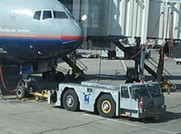 |
Large aircraft cannot be moved by hand and must have a tractor or tug. Pushback tractors use a low-profile design to fit under the aircraft nose. For sufficient tractor the tractor must be heavy, and most models can have extra ballas added. A typical tractor for large aircraft weighs up to 54 tonnes (59.5 short tons; 53.1 long tons; 119,000 pounds) and has a drwbar pull of 334 kN (75,000 lbf). Often the driver's cabin can be raised for increased visibility when reversing and lowered to fit under aircraft. |
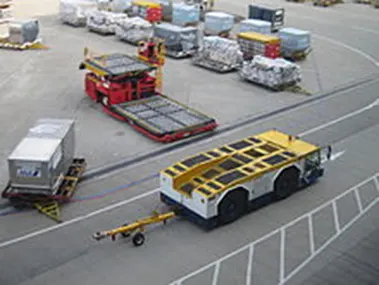 |
Conventional tugs use a tow bar to connect the tug to the nose landing gear of the aircraft. The tow bar is fixed laterally at the nose landing gear, but may move slightly vertically for height adjustment. At the end that attaches to the tug, the tow bar may pivot freely laterally and vertically. |
|
Towbar less (TBL) tractors do not use a towbar; they scoop up the nose landing gear and lift it off the ground. This avoids the time penalty of connecting/disconnecting a towbar, and entirely removes the cost/complexity of maintaining towbars on the ramp. The tug itself does not need to be particularly massive - the aircraft's nosewheel weight provides the necessary downward force. |
Take off:
Takeoff is the phase of flight in which an aircraft goes through a transition from moving along the ground (taxiing) to flying in the air, usually starting on a runway. Usually the engines are run at full power during takeoff. Following the taxi motion, the aircraft stops at the starting line of the runway. Before takeoff, the engines, particularly piston engines, are routinely run up at high power to check for engine-related problems. This makes a consid- erable noise. When the pilot releases the brakes, the aircraft starts accelerating rapidly until the necessary speed for take-off is achieved.The takeoff speed required varies with air den- sity, aircraft weight, and aircraft configuration (flap and/or slat position, as applicable). Air density is affected by factors such as field ele- vation and air temperature.Operations with transport category aircraft employ the concept of the takeoff V-Speeds, V1 and V2. These speeds are determined not only by the above factors affecting takeoff perform- ance, but also by the length and slope of the runway. Below V1, in case of critical failures, the takeoff should be aborted; above V1 the pilot continues the takeoff and returns for land- ing. After the co-pilot calls V1, Then, V2 (the safe takeoff speed) is called. This speed must be maintained after an engine failure to meet per- formance targets for rate of climb and angle of climb.
The speeds needed for takeoff are relative to the motion of the air (indicated airspeed). A head wind will reduce the ground speed needed for takeoff, as there is a greater flow of air over the wings. This is why the aircrafts always take off against the wind. Side wind is not preferred as it would disturb the stability of the aircraft. Typical takeoff air speeds for jetliners are in the 130–155 knot range (150–180 mph, 240–285 km/h). For a given aircraft, the takeoff speed is usually directly proportional to the aircraft weight; the heavier the weight, the greater the speed needed. Some aircraft have difficulty generating enough lift at the low speeds encountered during takeoff. These are therefore fitted with high-lift devices, often including slats and usually flaps, which increase the camber of the wing, making it more effective at low speed, thus creating more lift. These have to be deployed from the wing before performing any maneuver.At the beginning of the climb phase, the wheels are retracted into the aircraft and the undercarriage doors are closed. This operation is audible by the passengers as a noise coming from below the floor.
5. Learn about take-off power, tyre design, rolling resistance, tyre pressure, brake forces when landing.
Take-off Power:
The total energy of an aircraft flying in the atmosphere can be calculated using equation,
E = ½ m v2+ mgh
where , m = total mass of the aircraft
v = velocity with which air craft is moving.
g = acceleration due to gravity
h = height at which aircraft is moving
A Boeing 737-300 has a maximum takeoff weight of 5.65 × 10⁴ kg, a cruise altitude of h = 10,195 m, and cruise speed of 221 m/sec. Inserting these numbers into the above equation, we obtain 7.03 GJ for the energy at cruise conditions. However, the engines mounted onto the wings of the plane are required to provide additional energy per time, power, in order to keep the aircraft flying at a constant altitude and speed. However, the engines mounted onto the wings of the plane are required to provide additional energy per time, power, in order to keep the aircraft flying at a constant altitude and speed. This extra power needed to overcome the drag acting on the airplane and is calculated using
P = (dh/dt) m g
where (dh/dt) is the decent speed required to keep the plane's speed constant if the engines fail.
m = mass of the aircraft
g = acceleration due to gravity
(ii) Tyre Design:
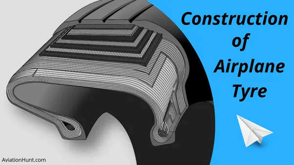
When it comes to safety, tyres are one of the most important components of aircraft. They help to absorb the shock of landing and provide cushioning. It also provides the necessary traction for braking and stopping of an aircraft.An aircraft tyre is designed to withstand extremely heavy loads while landing, take off, taxing, and parking. The number of wheels required for aircraft increases with the weight of the aircraft, as the weight of the aeroplane needs to be distributed more evenly.
A Boeing 737NG & 737MAX uses 6 wheels, Boeing 787 uses 10 wheels, Boeing 777 uses 14 wheels and Airbus A380 uses 22 wheels. Aircraft tyres work under extreme conditions, carrying up to 340 tons and accelerating at over 250 km/hour at takeoff, in addition to enduring varied environmental stress when in flight and taxiing. Carcass plies are used to form the tire. They are sometimes called casing plies. An aircraft tyre is constructed for the purpose it serves. They support the weight of an aircraft while it is on the ground. It also provides the necessary traction for braking and stopping of an aeroplane. Tyre also helps to absorb the shock of landing and provide cushioning the roughness of take-off, roll-out, and taxi operations. Unlike an automobile or truck tyre, it does not have to carry a load for a long period of continuous operation. However, an aircraft tyre absorbs the high impact loads of landing, and also, it’s operating at high speeds for a short time when required.
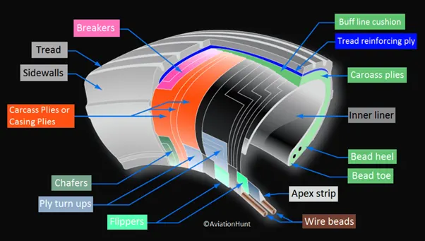
These are the technical aspects of the tyre, .
Retreading – Retreading is methods of restoring a worn tyre by renewing the tread area or by renewing the tread area plus one or both sidewalls. Repairs are included in the tyre retreading process.
Load Rating – Load rating is the maximum permissible load at a specified inflation pressure.
Ply Rating – Ply Rating is used to identify the maximum recommended load rating and inflation pressure for a specified tyre. It is an index of tyre strength.
Speed Rating – The speed rating is the maximum take-off speed to which the tyre has been tested.
Skid Depth – Skid depth is the distance between the tread surface and the deepest groove as measured in the mould.
Aircraft tyres must have an approved speed and load rating and have sufficient clearance when retracted through landing gear to allow for tyre growth. Tyre growth is the increase in the size of the tyre due to centrifugal forces at high speed.
Aircraft tyres may be Tube-type or Tubeless - Tubeless tyres are more advantageous over tube-type. There is no longer the use of tube-type tyre in recent aviation. Nowadays all airliners are using tubeless tyres. Tubeless that are meant to be used without a tube has the word TUBELESS on the sidewall of the tyre.
Aircraft tyres may be Radial or Bias - Almost all airliners are using Radial tyre. Bias is an older design, and it’s mainly used for road vehicles. Radial tyres have the word RADIAL on the sidewall. Radial tires are more expensive than bias-ply tyres. Radial tires are in demand because of their lower life cycle cost and long-term value.
Chines - Chines are also called deflectors. Chine tyre used on the nose wheel of aircraft, especially fuselage-mounted jet engines. It diverts runway water away from the engine inlets. Chines are circumferential protrusions that are moulded into the sidewall of nose tyres that deflect water sideways to help reduce excess water ingestion into the engines. Tyres may have chines on one or both sides, depending on the number of nose tyres on the aircraft.
Aircraft Tyre Standards - Each tyre manufacturer produces their own designs of the tyre with different tread patterns, wear patterns, wear limits etc, and in some cases, different names for the same part of the tyre. But all tyres must meet the approved standards before being accepted by the FAA or CAA. All commercial aircraft tyres approved under FAA Requirement Technical Standard Order (TSO) C62. A TSO is a minimum performance standard for specified materials, parts, and appliances used on civil aircraft.
(iii) Rolling Resistance Force:
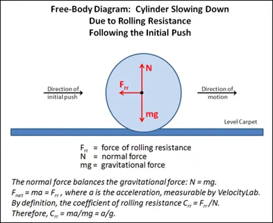
The coefficient, is a function of tire material, tire structure, tire temperature, tire inflation pressure, tread geometry, road roughness, road material and the presence or absence of liquids on the road. The value varies with speed. Tire pressure increases its value decreases need to be carefully choose value as per typical case under consideration.
Frr = Urr*m*g
where, Frr = Rolling resistance force
Urr = Constant of proportional is represented as rolling resistance coefficient
m = Mass of the vehicle
g = The gravitational acceleration constant
For the common range of inflation pressure, this equation can be used for a passenger car on a concrete road with acceptable accuracy for speeds upto 128 km/hr.
This equation for rolling resistance coefficient is, Urr = 0.01(1+0.001v)
Depending upon the velocity, the Urr value changes.
(iv) Tyre pressure:
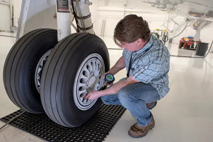
Aircraft tires are usually inflated with nitrogen to minimize expansion and contraction from extreme changes in ambient temperature and pressure experienced during flight. Dry nitrogen expands at the same rate as other dry atmospheric gases (normal air is about 80% nitrogen), but common compressed air sources may contain moisture, which increases the expansion rate with temperature.
The requirement that an inert gas, such as nitrogen, be used instead of air for inflation of tires on certain transport category airplanes was prompted by at least three cases in which the oxygen in air-filled tires combined with volatile gases given off by a severely overheated tire and exploded upon reaching auto-ignition temperature. The use of an inert gas for tire inflation will eliminate the possibility of a tire explosion. Aircraft tires generally operate at high pressures, up to 200 psi (14 bar; 1,400 kPa) for airliners, and even higher for business jets.
(v) Brake Forces When Landing:
All The commercial aircraft have automatic brake systems. Just like a car, these systems also have Anti-Lock Braking System (ABS) that prevents the tires from sliding down a wet runway. The advantage of the automatic brake system is that the aircraft brakes comfortably at a constant deceleration. Passengers experience a constant force that presses them into their seats. The brake system automatically applies the wheel brakes just enough to create a constant deceleration independent of the air resistance, spoilers and reversers. It is only in the last phase of brakes by pressing on both brake pedals. This deactivates the automatic brake system. Immediately after landing, the aircraft is still moving fast enough that aerodynamic devices are much more efficient that the brakes.
The brake units are powered by the hydraulics system. An electrical signal is sent from the flight deck to hydraulic actuators near the main landing gear. Here, hydraulic fluid at 3,000 pound per square inch is used to force the brake unit against the wheel, thus slowing it down.
6. With necessary assumptions, calculate the force and power required to push/pull an aircraft by a towing vehicle.
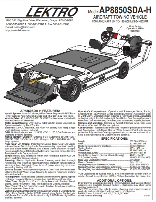
From the above image the values are assumed to find out the power and Torque
To calculate the force and Power to push or pull an aircraft by a towing vehicle we need to ṭake rolling resistance and aerodynamics of the vehicle into consideration
(a) Rolling Resistance force(Frr)
To find the Rolling resistance Force of the aircraft, Frr = Urr*m*g
The mass of the aircraft = 50000 kg
The mass of the towing vehicle = 4750 kg
The total mass of the aircraft and the towing vehicle = 54750 kg
Coefficient of rolling resistance force(Urr) = 0.02
gravitational constant, g = 9.81 m/sec^2
Rolling resistance Force of the aircraft and the towing, Frr = Urr*m*g
= 0.02*54750*9.81
= 10741.95 N
(b) Drag Force (F)
The drag equation states that drag D is equal to the drag coefficient Cd times the density r times half of the velocity V squared times the reference area A. D = Cd * A * .5 * r * V^2. For given air conditions, shape, and inclination of the object, we must determine a value for Cd to determine drag.
ρ = Density of Air Medium
A = Frontal Area Of the Vehicle which strike the Air
V = Velocity with which the vehicle moves
Cd = Coefficient of Drag Which varies different shapes of the frontal area.
Where,
D = Drag force
Cd = Drag Coefficient = 0.8
rho = Air density(kg/m^3) = 1.25
V = Velocity of Aircraft = 15kmph = 4.17 m/s
A = Frontal area = 19
Now Substituting the assumed values in the above formula gives us the Drag force of the Aircraft
Drag Force = 1/2*Rho*A*Cd*V^2
= 1/2*1.25*19*0.8*(4.17)^2
=165.19N
Therefore, the Drag force is = 165.19N
The total tractive force that the motor needs to overcome = Rolling Resistance force + Drag Force
Total forces acting on the towing vehicle = 10741.95 +165.19= 10907.14 N
The Total tractive Force that the Motor needs to overcome in order to push/pull the Aircraft = 10907.14 N = 10.907KN
The Power required to push/pull the airplane :
The power required by the motor is given by the velocity with which the towing operation takes place.
The average speed of push/pull = 15 kmph = 4.17m/s
Power required by the motor = Total Force*Velocity = 10.907*4.17 = 45.482KW
Power Required by The Motor = 45.482 kw
Torque required by motor = Force* radius =10.907*29 = 316.303 Nm
7. Design an electric powertrain with a type of motor, it’s power rating, and energy requirement to fulfil aircraft towing application. Estimate the duty cycle range to control the aircraft speed from zero to highest. Make all required assumptions. Prepare a table of assumed parameters. Draw a block diagram of powertrain.
From the previous question we are recalling the values of Aircraft and towing machine:
The total mass of the aircraft = 50000 kg
The total mass of the towing vehicle = 4750 kg
Coefficient of rolling resistance force(Urr) = 0.02
gravitational constant, g = 9.81 m/sec^2
Cd = Drag Coefficient = 0.8
rho = Air density(kg/m^3) = 1.25
V = Velocity of Aircraft = 15kmph = 4.17 m/s
A = Frontal area = 19
Total Rolling Resistance Force, Frr = 10741.95 N
Drag force, Fad = 165.19N
Total forces acting on the towing vehicle= 10907.14 N
Power Required by The Motor = 45.482KW
Torque required by motor = 316.303 Nm
Starting with the Motor
Motor Design :
So let us assume a 50 KW DC Brushless motor :
Nominal Power: 50 KW
Nominal Voltage: 800v
Nominal current:400A
RPM: 1500-4000RPM
From the above motor design :
(i) Power Rating:
Rated Voltage = 800 V
Rated current = 400 Amps
Rated power = Voltage(V)*Current(I) = 800*400 = 320000W = 320 KW
So from the above choosen motor the output power will be 320 KW and the power required by the towing vehicle is 45.482kW
Input Power to Towing Vehicle =45.482 KW
Total Power(Rated) can be supplied = 50 KW
(ii) Duty cycle Efficiency = Output Power/Input Power
Duty cycle, D = 45.482/50
Duty cycle, D = 0.906 = 90%
The Duty cycle percentage = 60%
(iii)Energy requirement to fulfil aircraft towing application.
Total energy supplied to move the towing vehicle = Power input to Towing mahine * Time taken to move the aircraft by Towing vehicle
Energy(E) = Power * time(t)
Power = 45.482 KW
Time (t) = time taken to move the aircraft by towing vehicle = 20 min = 0.333 hrs
Energy(E) = 45.48*0.33
Energy(E) = 15.0084 KWh
Energy required to move aircraft by towing vehicle for 15 minutes = 15.0084 KWh
Energy required to move aircraft by towing vehicle for 15 min with 6 KMPH velocity = 15.0084 KWh
Table of Assumed Parameters:
| The total mass of the towing vehicle | 4750 kg |
| The total mass of te aircraft | 50000kg |
| Coefficient of rolling resistance force(Urr) | 0.02 |
| gravitational constant, g | 9.81 m/sec^2 |
| Cd = Drag Coefficient | 0.8 |
| rho = Air density(kg/m^3) | 1.25 |
| V = Velocity of Aircraft | 4.17 m/s |
| A = Frontal area | 19 |
| Total Rolling Resistance Force, Frr | 10741.95 N |
| Drag force, Fad | 165.19N |
| Total forces acting on the towing vehicle | 10907.14 N |
| Power Required by The Motor | 45.482KW |
| Torque required by motor | 45.482KW |
Block Daigram of electric Powertrain:
CONCLUSION :
- Explained and Listed out the various types and weights of aircrafts.
- Explained the difference between ground speed and air speed.
- Explained the reasons why aircraft engine is not propelled to move on the ground before it is taken into runway.
- Explained how aircraft is pushed to runway when its ready to take off.
- Learned about take off power, tyre design, rolling resistance, tyre pressure, brake forces when landing.
- Calculated the force and power required to push / pull an aircraft by a towing vehicle.
- Designed the electric vehicle powertrain with motor rating, duty cycle with which motor is controlledusing controller and also energy, power, Torque is calculated to move the aircraft with the Towing
Vehicle.
References:
https://www.lektro.com/products/ap8850sda-h/
https://www.mgm-compro.com/products/50-80kw-electric-motors/