Project-1: Powertrain for aircraft in runways
Part A:
1. Search and list out the total weight of various types of aircrafts.
The weight of the aircraft is needed to be calculated by the pilot for every flight to ensure the aircraft remains within the weight limitations set by the manufacturer. These limitations are to ensure the aircraft is able to perform and recover from all flight maneuvers and withstand structural loading.
An aircraft’s empty weight, fuel, passengers & cargo must not weigh more than the aircraft’s Maximum Gross Takeoff Weight.
| Aircraft | Empty Weight | Max Fuel Weight | Max Cargo Weight | Max Gross Takeoff Weight |
| Antanov AN-225 | 285,000 kg | 300,000 kg | 190,000 kg | 640,000 kg |
| Airbus A380-800 | 277,000 kg | 254,000 kg | 84,000 kg | 575,000 kg |
| Boeing 747-800 | 220,100 kg | 194,000 kg | 134,000 kg | 447,700 kg |
| Airbus A340-500 | 168,000 kg | 175,000 kg | 54,000 kg | 372,000 kg |
| Boeing 777-300ER | 168,000 kg | 145,500 kg | 67,100 kg | 352,000 kg |
| Boeing 787-10 | 135,500 kg | 101,500 kg | 57,300 kg | 254,000 kg |
| Boeing 737-900 | 44,700 kg | 24,000 kg | 20,200 kg | 85,000 kg |
| Airbus A320-100 | 42,600 kg | 22,100 kg | 20,000 kg | 68,000 kg |
| Embraer 190 | 28,800 kg | 13,000 kg | 13,100 kg | 48,000 kg |
| Gulfstream G650 | 24,500 kg | 21,900 kg | 3,000 kg | 45,200 kg |
| Bombardier CRJ900 | 21,850 kg | 8,900 kg | 2,760 kg | 36,500 kg |
| Bombardier Q400 | 17,800 kg | 5,300 kg | 8,500 kg | 28,000 kg |
| Learjet 75 | 6,300 kg | 2,750 kg | 1,300 kg | 9,700 kg |
| Cessna Citation CJ4 | 4,700 kg | 2,650 kg | 1,000 kg | 7,800 kg |
| Beechcraft King Air B100 | 3,200 kg | 1,450 kg | 1,900 kg | 5,400 kg |
| Diamond DA50 RG | 1,450 kg | 155 lbs | 560 kg | 2,000 kg |
| Beechcraft Bonanza G36 | 1,150 kg | 200 kg | 385 kg | 1,660 kg |
| Cessna 206H | 990 kg | 235 kg | 520 kg | 1,630 kg |
| Sirrus SR22 | 1,000 kg | 220 kg | 430 kg | 1,630 kg |
| Cessna 172R | 770 kg | 170 kg | 255 kg | 1,100 kg |
2. Is there any difference between ground speed and air speed?
There are two different types of speed when talking about airplanes – ground speed and airspeed.
While ground speed is the airplane’s speed relative to the surface of the Earth, airspeed – at least true airspeed – is its speed relative to the air it is flying in.
Pilots commonly use three different types of airspeed: indicated airspeed, calibrated airspeed, and true airspeed.
Indicated airspeed is an airspeed that is calculated directly off an aircraft’s pitot-static system. It’s the calculated off the aircraft’s dynamic pressure – the difference between its total pressure and static pressure.
The dynamic pressure depends not only on the aircraft’s speed, but also on the density of the air it is flying in. As such, the higher the aircraft flies – and the lower the air density as a result – the bigger the difference between indicated and true airspeed is.
Calibrated airspeed is indicated airspeed adjusted for a variety of errors.
Just as an example, one of the things it’s adjusted for is the flap position. The reason for that is that at different flap positions, air flows differently around the pitot-static system and affects the indicated airspeed readings.
True airspeed is, the actual speed at which an aircraft is moving relative to the air it is traveling in. It’s calibrated airspeed adjusted for the the exact conditions (altitude, air temperature, etc.) that the aircraft is flying in.
Airspeed vs. Ground Speed
As mentioned above, true airspeed is simply the speed at which an aircraft is moving relative to the air it is flying in. As such, it’s also the speed at which the air is flowing around the aircraft’s wings.
Ground speed, on the other hand, is the aircraft’s speed relative to the ground. One thing that should be noted here is that it’s its horizontal rather than vertical speed – an aircraft climbing completely vertically would have a ground speed of zero.
In other words, while airspeed is what determines whether there is enough airflow around an aircraft to make it fly, ground speed is what determines how fast an aircraft will get to its destination.
Wind’s Effect on Ground Speed
The relationship between airspeed and ground speed is fairly simple. Ground speed is simply the sum of airspeed and wind speed.
If the aircraft is flying in the same direction as the wind is blowing, the aircraft experiences tailwind, and its ground speed is higher than its airspeed. On the other hand, if the wind is blowing against the direction the aircraft is traveling in, the aircraft experiences headwind, and its ground speed is lower than its airspeed.
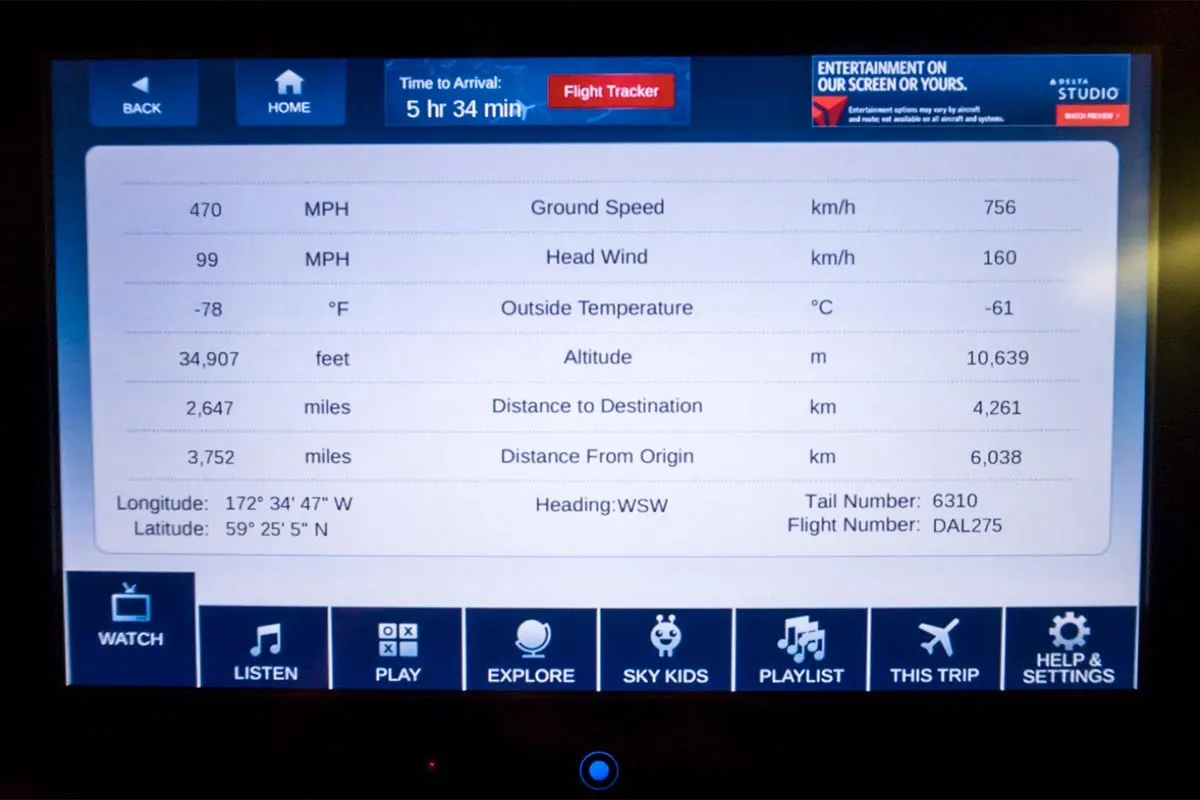
To give an actual example, imagine an aircraft that cruises at an airspeed of 500 miles per hour that has to cover a ground distance of 2,000 miles.
If there is no wind at all, then both the aircraft’s airspeed and ground speed would be the same 500 miles per hour, and the aircraft would reach its destination in four hours.
If there was a 100 miles per hour headwind – wind blowing against the aircraft’s direction of travel – the aircraft would still be traveling at an airspeed of 500 miles per hour. However, its ground speed would be just 400 miles per hour (100 miles per hour slower than its airspeed). And as such, it would take the aircraft five hours to reach its destinations.
Finally, if there was a 100 miles per hour tailwind – wind blowing in the same direction as the aircraft’s travel – the aircraft would still be traveling at an airspeed of 500 miles per hour, but its ground speed would be 100 miles faster. And, at 600 miles an hour, the aircraft would reach its destination in just three hours and twenty minutes.
3. Why is it not recommended to use aircraft engine power to move it on the ground at Airport?
Aircraft can move using their own engine power all the time on the airport apron and taxiways under their own power to go towards runways and after landing taxi to their assigned gate. But the thrust produced resulting jet blast might cause damage to the terminal building or equipment. Engines close to the ground may also blow sand and debris forward and then suck them into the engine, causing damage to the engine. A pushback is therefore the preferred method to move the aircraft away from the gate. And also it can reduce the cost for fuel. Taxiing can save money.
- Effectively a loss of control can happen, especially during high power engine running. Damage can occur to the aircraft itself, other aircraft nearby or to airsidestructures.
- There is a risk of injury to ground support personnel who may be in relatively close proximity to the aircraft.
- It is easier for truck driver to see the surroundings better than the pilot sitting in the cockpit with limited window. The pushback driver knows the airport better than the pilot.
- It also saves fuel virgin Atlantic hadproposed a new system in which pushback truck will move the aircraft all the way to runway to save fuel and reduce impact of environment.
- The plane engines are very loud. When more than one plane will add up their sound, than it will not be pleasent for passangers and others near airport.
4. How an aircraft is pushed to runway when its ready to take off?
Pushback:
IATA defines aircraft pushback as "rearward moving of an aircraft from a parking position to a taxi position by use of specialized ground support equipment."
Pushbacks at busy aerodromes are usually subject to ground control clearance to facilitate ground movement on taxiways.Once clearance is obtained, the pilot will communicate with the tractor driver (or a ground handler walking alongside the aircraft in some cases) to start the pushback. To communicate, a headset may be connected near the nose gear.
Since the pilots cannot see what is behind the aircraft, steering is done by the pushback tractor driver and not by the pilots. Depending on the aircraft type and airline procedure, a bypass pin may be temporarily installed into the nose gear to disconnect it from the aircraft's normal steering mechanism.
Once the pushback is completed, the towbar is disconnected, and any bypass pin removed. The ground handler will show the bypass pin to the pilots to make it clear that it has been removed. The pushback is then complete, and the aircraft can taxi forward under its own power.
Taxi:
Taxiing refers to the movement of an aircraft on the ground, under its own power. The aircraft moves on wheels. An airplane uses taxiways to taxi from one place on an airport to another; for example, when moving from a terminal to the runway.
The aircrafts always moves on the ground following the yellow lines, to avoid any collision with the surrounding buildings, vehicles or other aircrafts. The taxiing motion has a speed limit. Before making a turn, the pilot reduces the speed further to prevent tire skids. Just like cars, there is a certain list of priorities during taxiing. The aircrafts that are landing or taking off have higher priority. The other aircrafts have to wait for these aircrafts before they start or continue taxiing.
The thrust to propel the aircraft forward comes from its propellers or jet engines. Steering is achieved by turning a nose wheel or tail wheel/rudder; the pilot controlling the direction travelled with their feet. The use of engine thrust near terminals is restricted due to the possibility of jet blast damage. This is why the aircrafts are pushed back from the buildings by a vehicle before they can start their own engines for taxiing.
Take-off:
Takeoff is the phase of flight in which an aircraft goes through a transition from moving along the ground (taxiing) to flying in the air, usually starting on a runway. Usually the engines are run at full power during takeoff. Following the taxi motion, the aircraft stops at the starting line of the runway. Before takeoff, the engines, particularly piston engines, are routinely run up at high power to check for engine-related problems. This makes a consid- erable noise. When the pilot releases the brakes, the aircraft starts accelerating rapidly until the necessary speed for take-off is achieved.
The takeoff speed required varies with air density, aircraft weight, and aircraft configuration (flap and/or slat position, as applicable). Air density is affected by factors such as field ele- vation and air temperature.
Operations with transport category aircraft employ the concept of the takeoff V-Speeds, V1 and V2. These speeds are determined not only by the above factors affecting takeoff perform- ance, but also by the length and slope of the runway. Below V1, in case of critical failures, the takeoff should be aborted; above V1 the pilot continues the takeoff and returns for land- ing. After the co-pilot calls V1, Then, V2 (the safe takeoff speed) is called. This speed must be maintained after an engine failure to meet per- formance targets for rate of climb and angle of climb.
The speeds needed for takeoff are relative to the motion of the air (indicated airspeed). A head wind will reduce the ground speed needed for takeoff, as there is a greater flow of air over the wings. This is why the aircrafts always take off against the wind. Side wind is not preferred as it would disturb the stability of the aircraft. Typical takeoff air speeds for jetliners are in the 130–155 knot range (150–180 mph, 240–285 km/h). For a given aircraft, the takeoff speed is usually directly proportional to the aircraft weight; the heavier the weight, the greater the speed needed. Some aircraft have difficulty generating enough lift at the low speeds encountered during takeoff. These are therefore fitted with high-lift devices, often including slats and usually flaps, which increase the camber of the wing, making it more effective at low speed, thus creating more lift. These have to be deployed from the wing before performing any maneuver.
At the beginning of the climb phase, the wheels are retracted into the aircraft and the undercarriage doors are closed. This operation is audible by the passengers as a noise coming from below the floor.
5. Learn about take off power, tyre design, rolling resistance, tyre pressure, brake forces when landing.
Take-Off Power:
The Take-off Power is the amount of power that an engine is allowed to produced for a limited period of time for take-OFF.
The normal take-off is one in which the airplane is headed into the wind, or the wind is very light. Also, the takeoff surface is firm and of sufficient length to permit the airplane to gradually accelerate to normal lift-off and climb-out speed, and there are no obstructions along the takeoff path.
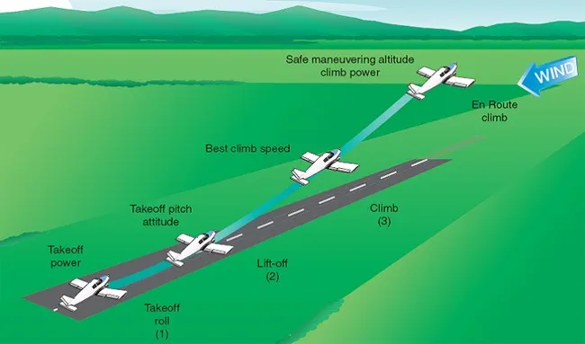
the airplane should be carefully aligned with the intended takeoff direction, and the nose wheel positioned straight, or centered. After releasing the brakes, the throttle should be advanced smoothly and continuously to takeoff power. An abrupt application of power may cause the airplane to yaw sharply to the left because of the torque effects of the engine and propeller.
There are two reasons for making a takeoff as nearly into the wind as possible:
- Aircraft speed will be less, therefore reducing wear and stress on landing gear
- Shorter ground roll and therefore much less runway length
The total energy of an aircraft flying in the atmosphere can be calculated using equation,
E = ½ m v2+ mgh
However, the engines mounted onto the wings of the plane are required to provide additional energy per time, power, in order to keep the aircraft flying at a constant altitude and speed. This extra power needed to overcome the drag acting on the airplane and is calculated using
P = (dh/dt) m g
where (dh/dt) is the decent speed required to keep the plane's speed constant if the engines fail.
Tyre Design:
Carcass plies are used to form the tyre. They are sometimes called casing plies. An aircraft tyre is constructed for the purpose it serves.
- They support the weight of an aircraft while it is on the ground.
- It also provides the necessary traction for braking and stopping of an aeroplane.
- Tyre also helps to absorb the shock of landing and provide cushioning the roughness of takeoff, roll-out, and taxi operations.
Unlike an automobile or truck tyre, it does not have to carry a load for a long period of continuous operation. However, an aircraft tyre absorbs the high impact loads of landing, and also it’s operating at high speeds for a short time when required.
Retreading – Retreading is methods of restoring a worn tyre by renewing the tread area or by renewing the tread area plus one or both sidewalls. Repairs are included in the tyre retreading process.
Load Rating – Load rating is the maximum permissible load at a specified inflation pressure.
Ply Rating – Ply Rating is used to identify the maximum recommended load rating and inflation pressure for a specified tyre. It is an index of tyre strength.
Speed Rating – The speed rating is the maximum takeoff speed to which the tyre has been tested.
Skid Depth – Skid depth is the distance between the tread surface and the deepest groove as measured in the mould.
Aircraft tyres must have an approved speed and load rating and have sufficient clearance when retracted through landing gear to allow for tyre growth. Tyre growth is the increase in the size of the tyre due to centrifugal forces at high speed.
Tubeless tyres are more advantageous over tube-type. There is no longer the use of tube-type tyre in recent aviation. Nowadays all airliners are using tubeless tyres. Tubeless that are meant to be used without a tube has the word TUBELESS on the sidewall of the tyre.
Almost all airliners are using Radial tyre. Bias is an older design, and it’s mainly used for road vehicles. Radial tyres have the word RADIAL on the sidewall. Radial tires are more expensive than bias-ply tyres. Radial tires are in demand because of their lower life cycle cost and long term value.
Rolling Resistance:
The force that resists the motion of a body rolling on a surface is called the rolling resistance or the rolling friction.
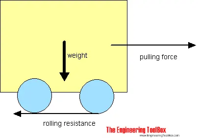
The rolling resistance can be expressed by the generic equation
Fr = c W (1)
where
Fr = rolling resistance or rolling friction (N, lbf)
c = rolling resistance coefficient - dimensionless (coefficient of rolling friction - CRF)
W = m ag
= normal force - or weight - of the body (N, lbf)
m = mass of body (kg, lb)
ag = acceleration of gravity (9.81 m/s2, 32.174 ft/s2)
Note that the rolling resistance coefficient - c - is influenced by different variables like wheel design, rolling surface, wheel dimensions and more.
The rolling resistance can alternatively be expressed as
Fr = cl W / r (2)
where
cl = rolling resistance coefficient - dimension length (coefficient of rolling friction) (mm, in)
r = radius of wheel (mm, in)
Tyre Pressure:
Aircraft tyres are too rigid to be forced onto a rim like automotive tyres. Aircraft wheel hubs come in two parts. The inboard and outboard hubs are bolted together with the tyre in the center, then pressurized with nitrogen.

The typical airliner tyre can handle a 38-ton load. It can meet the ground 500 times before needing a re-tread, a refresh it can take on seven times in its life. The key to their remarkable durability is maximizing the air pressure. The high-flying rubber is typically inflated to 200 psi, and the tyres on an F-16 fighter are pumped to 320 psi.
Because aircraft tyres operate at such high extremes of pressure, load, and speed, their care and service is critically important. The most important action an operator can take to prevent tyre-related events is to maintain proper tyre inflation pressure. Failure to keep aircraft tyres properly inflated can lead to very serious consequences. The most serious of these is the structural failure of the tyre. If the tyre operates underinflated or overdeflected/overloaded, the nylon cords which form the structure of the tyre go in and out of compression as the tyre rotates. This weakens the cords – much like a paperclip which is bent back and forth – until eventually the cords break. If enough cords break, the entire structure will eventually fail.
Another serious consequence of under-inflation is the thrown tread. Overdeflection increases shear between components in the tyre as it rolls in and out of contact and deforms. This results in a more rapid build‐up of heat within the tyre than would be evident if the tyre were properly inflated. At some point the excessive heat will cause the rubber to revert, or reverse cure. This reverted rubber is like grease with no strength or adhesion to contain the structure. This can allow the tyre to decompose, throwing the entire tread or pieces of it. In addition to destroying the tyre, thrown treads often result in expensive aircraft damage.
Brake Forces when Landing:
The main part of the aircraft kinectics energy is dissipated by the brake system when landing. The brake force is derived from the counter torque to the wheels movement, which is generated from the brake system actuators. The Figure shows the forces acting on the aircraft and the wheels during braking time and its electrical equivalent.
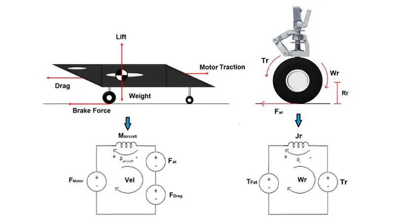

where,

The normal force on the aircraft depends on its weight and lift acting on the braking moment. The normal force corresponding to each wheel, considering that each wheel receives one third of the resulting force is described as follows:
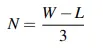
where,
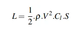
Tr is the counter torque generated by the brake actuator and FMotor is the motor traction. The wheel and aircraftequations are related by the wheel slip. The slips relates the aircraft speed and the wheel speed, as described by the following equation
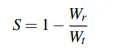
where,

Part B:
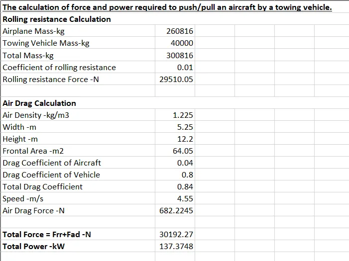
6. A. With necessary assumptions, calculate the force and power required to push / pull an aircraft by a towing vehicle.
1] Rolling Resistance Force (Frr) = Crr⋅m⋅g
Where, Frr= Rolling Resistsnce Force in N
Crr= Coefficient of Rolling resistsnce
g = Gravity 9.81
2] Aerodynamic Force (Fad)=0.5⋅Cd⋅ρ⋅A⋅V^2
Where, Fad= Aerodynamic Force in N
Cd = Drag Coefficient
ρ = Air Density in Kg/m^3
A = Frontal Area in m^2
V= Velocity of Vehicle in m/s
3] Total Force (Ft) = Frr+Fad
Where, Frr= Rolling Resistance in N
Fad= Aerodynamic Fornce in N
4] Power Required (Pr) = Ft⋅V
Where, Ft= Total Force in N
V= Velocity of Vehiclein m/s
Assuming the values for Boeing 777 Airplane,
B. Develop the model for the calculated force and power using Simulink.
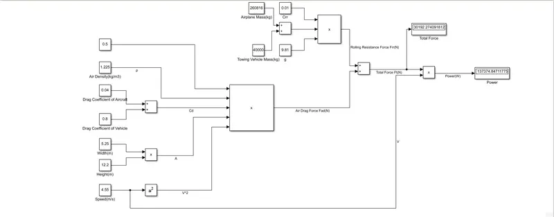
Blocks Used: Constant, Add, Product, Square, Display
Logic: Rolling Resistance Calculation is achieved by Constant, Add and Product blocks as per above equation. Air Drag Calculation is done by Constant,Add, Product, Square Blocks as per above equation. Both these values are fed as input to Add block to get Total Force. Then this is fed to Product block with Speed block to get the Power. Outputs are shown via Display Block.
Simulink Model:
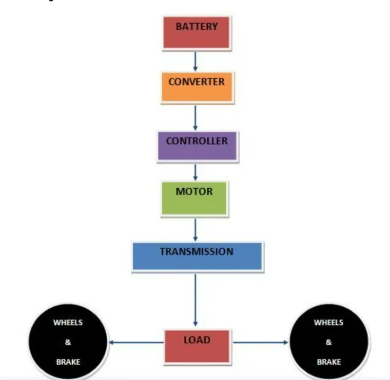
7. A. Design an electric powertrain with type of motor, it’s power rating, and energy requirement to fulfill aircraft towing application in Simulink. Estimate the duty cycle range to control the aircraft speed from zero to highest. Make all required assumptions. Prepare a table of assumed parameters. Draw a block diagram of powertrain.
(Hint :DC7 Block)
Considering the values from above question,
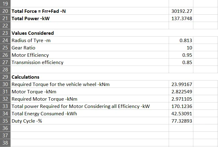
Rolling Resistance force for Aircraf(Frr)=29510.05 N (29.510KN)
Power Required Force Aircraft(Pr)=137.375Kw
Radius of Tyre (r) = 0.813m
Gear Ratio (G)=10
Motor Efficiency (ηm)=95% = 0.95
Transmission efficiency (ηt)=85% = 0.85
Required Torque for the vehicle wheel
Tw=Frr⋅r
Tw=29.510*0.813= 23.99KNm
Motor Torque
Tm=Tw/G⋅ηt
Tm= 23.99/10*0.85= 2.823KNm
Required Motor Torque
Tmr=Tm/ηm
Tmr= 2.823/0.95 = 2.97KNm
Total power Required for Motor Considering all Efficiency
Pt=Pr/ηm*ηt
Pt= 137.375/0.95*0.85 = 170.124kW
If we consider, The towing Vehicle operation was completed in 15 min i.e., 0.25 hours
Total Energy Consumed
Et=Pt⋅t
Et= 170.124*0.25 = 42.53KWh
If we consider the battery capacity=220 kw is used by the towing vehicle then. The duty cycle range to control the speed from O to max speed (3m/s) is given as
Dc=Pt/Pr
Dc=170.124/220=0.7733=77.33%
Therefore the controller will be able to provide a duty cycle ranging from 0 to 77.33% in order to control the towing speed.
Simulink Model with DC7:
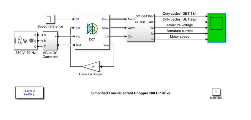
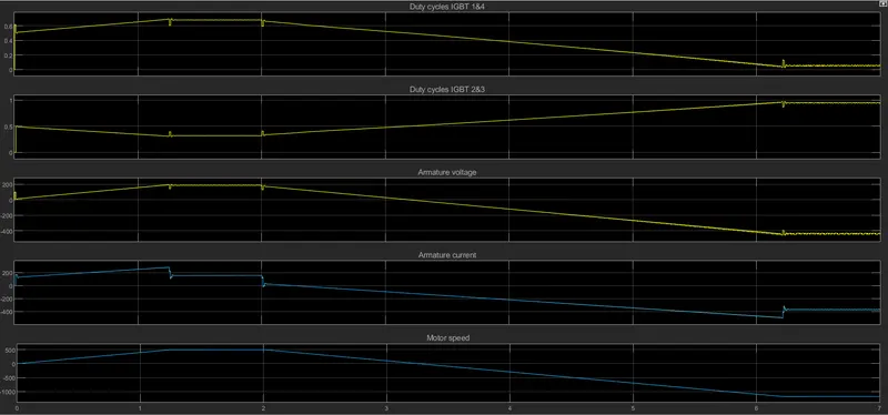
Output:
B. Also, Design the parameters in excel sheet.