Project-1: Powertrain for aircraft in runways
Project-1: Powertrain for aircraft in runways
Part A:
1. Search and list out the total weight of various types of aircrafts.
2. Is there any difference between ground speed and air speed?
3. Why is it not recommended to use aircraft engine power to move it on the ground at Airport?
4. How an aircraft is pushed to runway when its ready to take off?
5. Learn about take off power, tyre design, rolling resistance, tyre pressure, brake forces when landing.
Introduction-
Aircraft Authorized Gross Weight Limits (also referred to as certified weight limits) are laid down in the (AFM) or Associated Certificate of Airworthiness (C of A). The Authorized weight limits that can legally be used by an operator or airline are those listed in AFM and the weight and balance manual. The Authorized weight limits are chosen by the customer/ airline and they are referred to as “purchased weight”. The operator may purchase certified weight below the max. design weight because many of the operating fees are based on the aircraft AFM maximum allowable weight values. An aircraft purchase is typically a function of the certified weight purchased.
Maximum weights established for each aircraft, by design & certification must not be exceeded during aircraft operation (ramp or taxying, take-off, en-route flight, approach & landing) & during aircraft loading (zero fuel conditions, centre of gravity positions, weight distribution) weights could be restricted on some type of aircraft depending on the aircraft handling requirements, for e.g. Aerobatic Flight Aircraft, where certain Aerobatic Manoeuvres can only be executed with a limited gross weight. In addition, the authorised maximum weight limits may be less as limited by centre of gravity, fuel density and fuel loading limits.
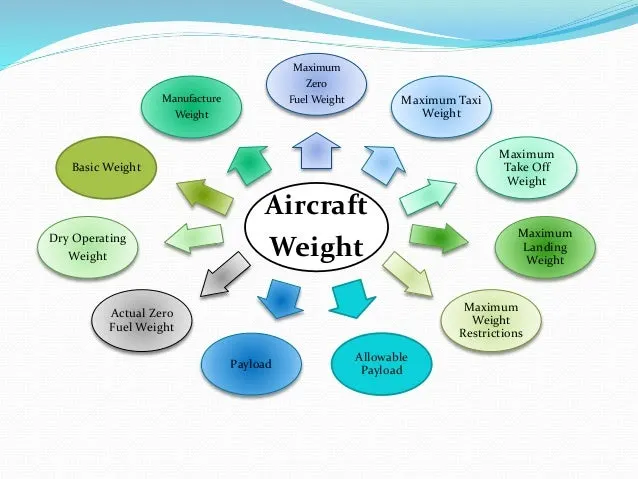
The above figure shows the Aircraft weight distribution.The different terms represent different weights or masses. For each flight, the weights are taken into account for several reasons.
When looking at different aircraft's specifications or in POHs/AFMs, there are several different weights of the aircraft mentioned (e.g. maximum take-off weight, maximum landing weight, operating empty weight). Let's broadly describe these weights one by one.
Manufacturer’s Empty Weight (MEW) –
It is also called Licensed Empty Weight
It is the weight of the aircraft “as built” & includes the weight of the structure, power plants, furnishing, installations, systems, & other equipment that are considered an integral part of the aircraft.
This includes baggage, passengers & usable fuel.
Zero Fuel Weight (ZFW) –
This is the total weight of the airplane and all its contents (including usable fuel), but excluding the total weight of the usable fuel on board.
As a flight progresses and fuel consumed, the total weight of the airplane reduces, but the ZFW remains constant.
Maximum Zero Fuel Weight (MZFW) is the maximum weight allowed before usable fuel and other specified usable agents (engine injection fluid & other consumable propulsion agents) are loaded.
Operating Empty Weight (OEW) –
It is roughly equivalent to Basic Empty Weight on light aircraft.
It is the basic weight of an aircraft including the crew, all fluids necessary for operation such as engine oil, engine coolant, water, usable fuel, & all operator items & equipment required for flight but excluding usable fuel but payload.
Payload –
It is the carrying capacity of an aircraft which includes cargo, people, extra fuel. In case of the commercial airliner, it may refer only revenue generating cargo or paying passengers.
Maximum Take-Off Weight (Maximum Brake Release Weight) –
The maximum weight authorized at brake release for take-off, or at the start of the take-off roll. The maximum take-off weight is always less than the maximum taxi/ramp weight to allow for fuel burned during taxi by the engines and the APU. In operation, the maximum weight for take-off maybe limited to values less than maximum take-off weight due to aircraft performance, environmental conditions, airfield characteristics (take-off field length, altitude), airspeed, maximum tyre speed, obstacle clearances, landing requirements, the maximum weight authorised for normal landing of an aircraft.The MLW mustn’t exceed MTOW.
Maximum Landing Weight-
This maximum weight at which an aircraft is permitted to land.
The following image depicts takeoff weight components.
Maximum Ramp Weight-
Also called maximum taxi weight (MTW). It is the maximum weight authorized for maneuvering (taxiing or towing) an aircraft on the ground.
Air Craft Gross weight-
It is the total aircraft weight at any moment during the flight or ground operation. This decreases during flight due to fuel and oil consumption.
The maximum landing weight is what the manufacturer has certified for landings. Generally, this is MTOW minus some fuel.
Note that every manufacturer has his own standard and might draw the lines between the different weight groups differently. Say, for one the engine quadrant is part of the propulsion system, whereas the other sees it as part of the control system.
- Basic Empty Weight (BEW) is the weight of the aircraft "as built" and includes the weight of the structure, power plant, furnishings, installations, systems and other equipment that are considered an integral part of an aircraft before additional operator items are added for operation.
- Dry Operating Wieght (DOW) BEW + Weight of Crew (Pilot + Cabin including their bags) + Pantry
- Operating Weight (OW) DOW + Takeoff fuel (i.e. Ramp Fuel - Taxi fuel)
- Maximum Zero Fuel Weight (MZFW) DOW + Payload (anything put on the aircraft that generates revenue to the company, e.g. passenger, baggage, cargo, mail and fret)
- Maximum Taxi Weight (MTW) MZFW + Ramp fuel
- Maximum Takeoff Weight (MTOW) MZFW + Takeoff fuel, or MTW - Taxi fuel
- Maximum Landing Weight (MLW) MTOW - Trip Fuel
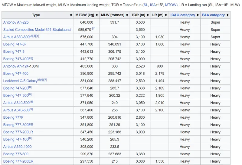
List Of Various types of Aircrafts-
2. Is there any difference between ground speed and air speed?
Pilots rely on four types of speed measurements when operating an aircraft: ground speed, true airspeed, indicated airspeed, and calibrated airspeed. The difference between airspeed and ground speed when discussing the speed of an aircraft is how the speed is measured. Ground speed is measured relative to the Earth below the plane while airspeed is measured relative to the air through which the plane is flying. Ground speed defines the measurement for how quickly a plane will reach its destination. Airspeed, on the other hand, provides a measurement for the effect of airflow on the plane’s ability to fly.
While Meter ground speed relies on one factor, horizontal distance, for measurement, airspeed is measured in different ways for a multitude of purposes. True airspeed measures only the flow of air around the plane, but pilots factor in additional variables to the indicated airspeed shown by the airspeed indicator in order to calculate calibrated airspeed. Indicated airspeed is calculated from the pitot-static system and measures the difference between the aircraft’s total pressure and its static pressure in order to find its dynamic pressure. Indicated airspeed relies on the height of the plane in the air because air density lessens as the plane climbs higher. Lower density creates a greater difference between true airspeed and indicated airspeed. The airspeed indicator is a pilot’s instrument which measures airspeed using only the differential between static pressure of the air and the dynamic pressure, or ram pressure, of the aircraft’s forward motion.
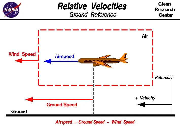
The groundspeed and the airspeed usually changes depending on the wind component.
If we decide that there is no wind component, then Ground Speed = Air Speed.
If wind is blowing in the tail direction of an aircraft, then (Air Speed > Ground Speed)
Air Speed = Wind Component + Ground Speed.
If wind is blowing in the head direction of the aircraft then, (Air Speed < Ground Speed)
Air Speed = Ground Speed - Wind Component.
Gravity plays major role in increasing the aircraft speed while it is descending.
3. Why is it not recommended to use aircraft engine power to move it on the ground at Airport?
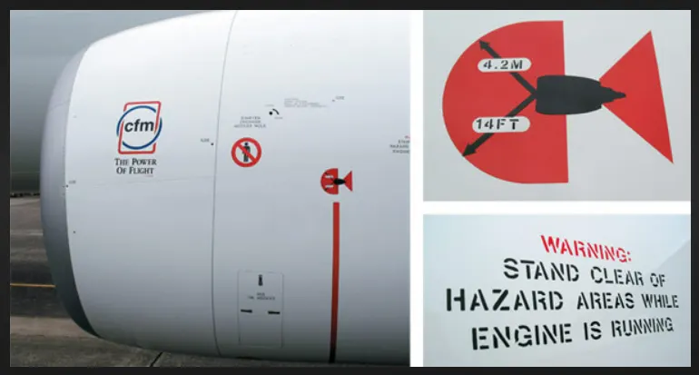
In airports, aircraft usually do not use their main engines to travel from shed's to runway i.e., when on the ground because of the following reasons:
- The jet blast from the engines can damage the terminal building and nearby Foreign equipment. It can even throw away people standing nearby because of huge pressure.
- Engines can blow sand and debris. Engines can suck in sand and debris which can cause serious damage to the engine. It is easier for the truck driver to see the surroundings better than the pilot sitting in the cockpit with limited windows.
• Modern planes are huge. It is difficult to navigate such gigantic structures through limited space. An A380 is eight stories high. The pilots won't be able to see anything directly in front of them or anything behind the wings.
-
The plane engines are very loud. This noise can add up substantially when multiple planes are moving around the airport. It won't be a pleasant experience for people sitting inside the terminal, as most people don't even like the sound of powerful motor-bikes. . It saves fuel.
4. How an aircraft is pushed to runway when its ready to take off?
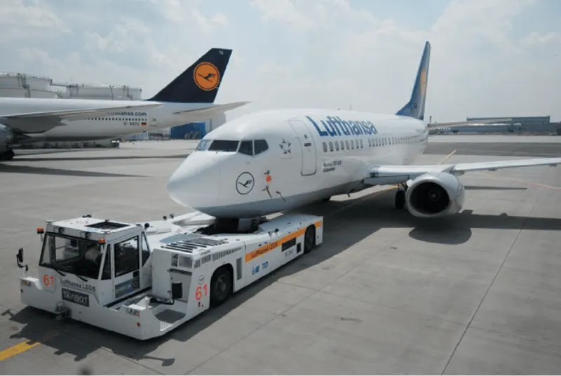
The vehicles used for this towing or moving from terminal to runway are called Taxiing. Here the fuel cost is also reduced to a great extent. And nowadays electric taxiing is becoming more economical and efficient way.Electric taxiing systems use electric motors fitted inside the wheels of the aircraft’s landing gear. Electric power is supplied to these motors by an on-board Auxiliary Power Unit (APU).
When aircraft is ready with all the passengers and luggages for the aviation then pushback is the aviation procedure during which an aircraft is pushed backwards away from an airport gate by external power. The aircrafts always move on the ground following the yellow lines, to avoid any collision with the surrounding buildings, vehicles, or other aircrafts. The taxiing motion has the speed limit. Before making a turn, the pilot reduces the speed further to prevent the tire skids. Just like cars, there is certain list of priorities during taxiing. The aircraft that are landing or taking off have higher priority. The other aircrafts have to wait for these aircrafts before they start or continue taxiing. The thrust to propel the aircraft forward comes from its propellers/jet engines. Steering is achieved by turning a nose wheel or tail wheel; the pilot controlling the direction travelled with their feet. The use of engine thrust near terminals is restricted due to the possibility of jet blast damage. This is why the aircrafts are pushed back from the buildings by a vehicle before they can start their own engines for taxiing.
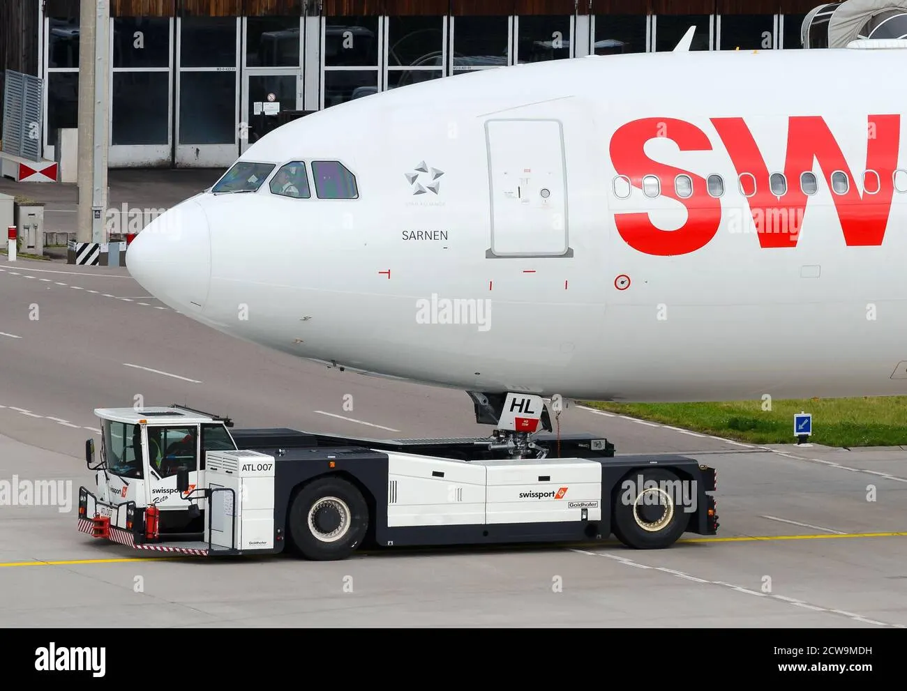
These are heavy weighing low profile vehicles with enormous torque to do the job of pushing/pulling the large aircraft from the terminals to the runway. The tractors are designed with extra weight purposefully to offer them enough traction to push or pull the heavy aircraft.
5.Learn about take off power, tyre design, rolling resistance, tyre pressure, brake forces when landing.
Take Off Power :-
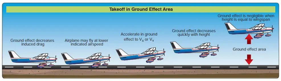
Take off is the horizontal distance covered on the ground to get an aircraft airborne. This is done by having the aircraft travel a certain distance known as the ground run upon which the control stick is pulled to lift the aircraft's nose. This creates an angle of attack to attain the lift co-efficient and the air acting on the wings generates lift and the aircraft then gets airborne. In light aricrafts 100% of the power is used for take off where as for heavier aircrafts about 85% engine power is used for take off in order to prolong the engine life. The equation to calculate the take off power is,
P=(T-d-F)*V
Where,
T = Thrust devloped by the engine.
d = Aerodynamic drag.
F = Rolling resistance of the aircraft.
Rolling Resistance :-
Also known as rolling friction, it is the resistance force of a spherical or round object when subjected to motion on a surface.With respect to aircrafts rolling resistance is the friction produced at the wheels during take off and landing. The equation of rolling resistance is given as,
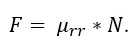
Where,
Urr = Co-efficient of friction
N = Normal force which is the force perpendicular to the surface on which the wheel is rolling.
Aircraft Tire Design :-
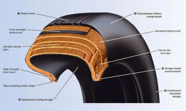
Aircraft tires may be tube-type or tubeless. They support the weight of the aircraft while it is on the ground and provide the necessary traction for braking and stopping. The tires also help absorb the shock of landing and cushion the roughness of takeoff, rollout, and taxi operations. Aircraft tires must be carefully maintained to perform as required. They accept a variety of static and dynamic stresses and must do so dependably in a wide range of operating conditions. Aircraft tires are classified in various ways by type, ply rating, whether they are tube-type or tubeless, and whether they are bias ply tires or radials. Identifying a tire by its dimensions is also used. The various types of tires are,
Type I tires which are used on fixed gear aircraft and are designated only by their nominal overall diameter in inches. These are smooth profile tires that are obsolete for use in the modern aviation fleet. They may be found on older aircraft.
Type III tires are common general aviation tires. They are typically used on light aircraft with landing speeds of 160 miles per hour or less. Type III tires are relatively low-pressure tires that have small rim diameters when compared to the overall width of the tire. They are designed to cushion and provide flotation from a relatively large footprint.
Type VII tires are high performance tires found on jet aircraft. They are inflated to high-pressure and have exceptional high load carrying capability. The section width of Type VII tires is typically narrower than Type III tires.
Type VIII aircraft tires are also known as three-part nomenclature tires. They are inflated to very high-pressure and are used on high-performance jet aircraft. The typical Type VIII tire has relatively low profile and is capable of operating at very high speeds and very high loads. It is the most modern design of all tire types. The three-part nomenclature is a combination of Type III and Type VII nomenclature where the overall tire diameter, section width, and rim diameter are used to identify the tire.
An aircraft tire is constructed for the purpose it serves. Unlike an automobile or truck tire, it does not have to carry a load for a long period of continuous operation. However, an aircraft tire must absorb the high impact loads of landing and be able to operate at high speeds even if only for a short time. The deflection built into an aircraft tire is more than twice that of an automobile tire. This enables it to handle the forces during landings without being damaged. The construction of an aircraft tire is shown above.
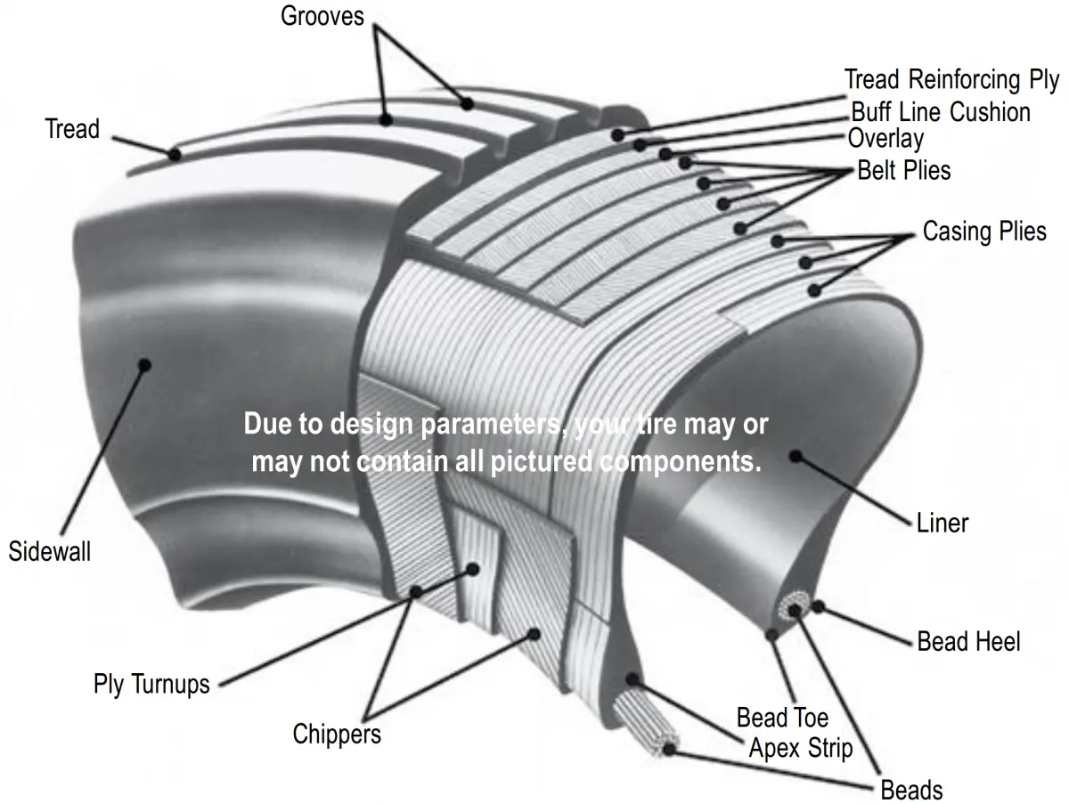
- Tire Bead: The tire bead is an important part of an aircraft tire. It anchors the tire carcass and provides a dimensioned, firm mounting surface for the tire on the wheel rim. Tire beads are strong. They are typically made from high-strength carbon steel wire bundles encased in rubber. One, two, or three bead bundles may be found on each side of the tire depending on its size and the load it is designed to handle. Radial tires have a single bead bundle on each side of the tire. The bead transfers the impact loads and deflection forces to the wheel rim.
- Carcass plies: Carcass plies, or casing plies as they are sometimes called, are used to form the tire. Each ply consists of fabric, usually nylon, sandwiched between two layers of rubber. The plies are applied in layers to give the tire strength and form the carcass body of the tire. The ends of each ply are anchored by wrapping them around the bead on both sides of the tire to form the ply turn-ups. As mentioned, the angle of the fiber in the ply is manipulated to create a bias tire or radial tire as desired. Typically, radial tires require fewer plies than bias tires.
- Tread: The tread is the crown area of the tire designed to come in contact with the ground. It is a rubber compoud formulated to resist wear, abrasion, cutting, and cracking. It also is made to resist heat build-up. Most modern aircraft tire tread is formed with circumferential grooves that create tire ribs. The grooves provide cooling and help channel water from under the tire in wet conditions to increase adhesion to the ground surface. Tires designed for aircraft frequently operated from unpaved surfaces may have some type of cross-tread pattern. The tread is designed to stabilize the aircraft on the operating surface and wears with use.
- Sidewall: The sidewall of an aircraft tire is a layer of rubber designed to protect the carcass plies. It may contain compounds designed to resist the negative effects of ozone on the tire. It also is the area where information about the tire is contained. The tire sidewall imparts little strength to the cord body. Its main function is protection.
Aircraft Tire Pressure :-
Aircraft tires are not the same as passenger car or truck tires. Unlike car tire, aircraft tires are not on the ground at all times and are only in contact with the ground during take off, landing and taxing. Particularly during take off and landing, the tires must be able to withstand extremely heavy impact loads for short durations. The figure below is a comparison between a car tire and aircraft tires.
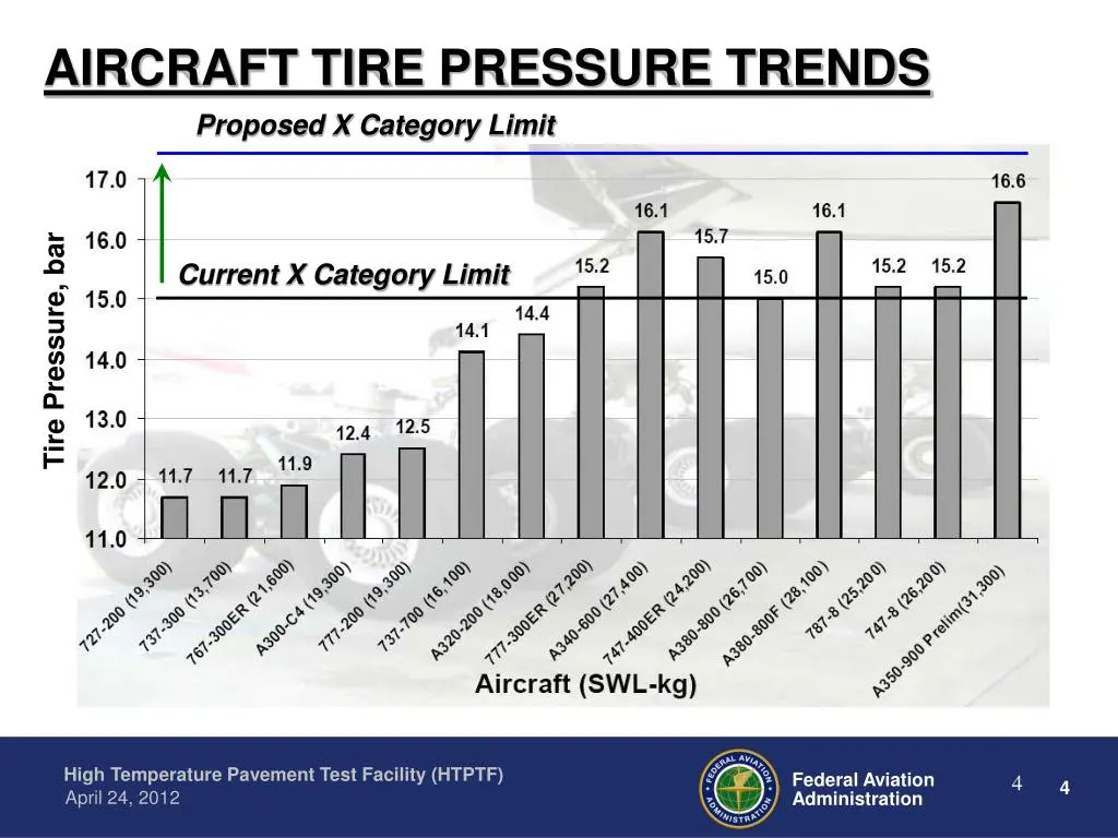
Because aircraft tires operate at such high extremes of pressure, load, and speed, their care and service is critically important. The most important action an operator can take to prevent tire-related events is to maintain proper tire inflation pressure. Failure to keep aircraft tires properly inflated can lead to very serious consequences. The most serious of these is the structural failure of the tire. If the tire operates underinflated or overdeflected/overloaded, the nylon cords which form the structure of the tire go in and out of compression as the tire rotates. This weakens the cords – much like a paperclip which is bent back and forth – until eventually the cords break. If enough cords break, the entire structure will eventually fail.
It is important to check the tire pressure everyday because of the high pressures and extreme temperatures at which aircraft tires operate, they do not hold air perfectly. An aircraft tire can lose up to 5 percent of its pressure in 24 hours and still be perfectly serviceable.
Braking Forces During Landing :-
Like a car aircrafts have disc brakes at the wheels to slow down the aircraft when it touches down, but the disc brakes alone are not sufficient for the plane to decelerate quickly and safely. Therefore air brakes and in some aircrafts reverse thrusters are used along with the disc brakes to safely bring the aircraft to a halt after landing. The braking process exerts a torque on the wheels due to which friction is produced. As a result, friction is produced with the ground, and it loses kinetic energy, and hence, the vehicle stops.
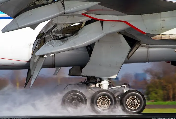
Friction, however, is massively dependent on the weight that rests on the wheels. In case of landing an airplane, the aerodynamic lift basically nullifies the weight of the plane and therefore makes braking while using the wheels extremely inefficient. As a result, the plane needs other ways to slow down until the aerodynamic lift and speed is sufficiently reduced. In modern aviation, this is done by two different braking systems: The Spoilers and the Reversers, that both are usually operated by a computer, which tries to reach a constant deceleration of convenient magnitude.
As soon as the wheels get in contact with the ground, the Spoilers are fully activated. These are flaps located on the back-end of the wings and can significantly reduce the aerodynamic lift as well as increase the drag. These flaps are extremely important for the braking process because without them the friction of the wheels is not sufficient for efficient braking. Basically, wheel brakes and Spoilers together can already be sufficient for slowing down an airplane.
However, to reduce the amount of stress the wheel brakes have to withstand, there is an additional system reversers. These are mechanisms located at the engines that can be activated to redirect the engine’s exhaust forward, rather than backwards (commonly referred to as thrust reversal). All three systems together can be used by a computer to reach an extremely smooth braking process without putting too much stress on the single components.
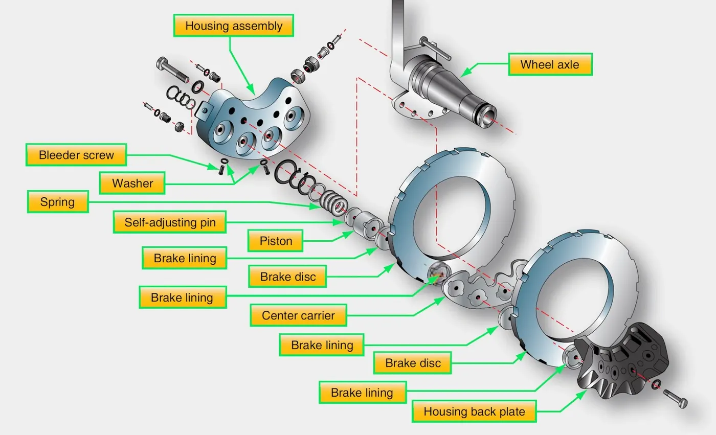
These 3 systems the disc brake, air brake or spoilers and the reverse thrusters together help bring the aircraft to a stop safely.
PART-B
6.A. With necessary assumptions, calculate the force and power required to push / pull an aircraft by a towing vehicle.
In order to calculate the power required by the towing tug to push/pull an aircraft, we must first calculate the forces that act on the vehicle. Since aircrafts operate on flat surfaces on the ground, the hill climbing force is not taken into consideration. Therefore the two forces acting on the towing tug during operation are aerodynamic drag force and rolling resistance force.
Calculation of rolling resistance,
The equation of rolling resistance is,
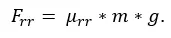
Where,
μrr - the co-efficient of rolling resistance.
m is the mass of the towing vehicle and the mass of the aircraft in Kg.
g is the acceleration due to gravity in m/s^2.
Lets consider mass of Aircraft=20000kg
mass of Towing vehicle = 8000kg
Therefore total mass m=28000kg.
μrr of aircraft =0.03
μrr of towing vehicle =0.02
Therefore total co-efficient of rolling resistance μrr=0.05
speed = 10kmph
velocity= 2.77m/s
Rolling resistance fore Frr= m* μrr * g
Frr= 28000*0.05*9.81
Frr= 13734 N
The equation for aerodynamic drag is,

Where,
ρ is the density of air in Kg/m^3. = 1.225kg/m^3
Cd is the co-efficient of drag. = (Cd of Aircraft + Cd of Towing vehicle) = (0.3+0.15)= 0.45
v is the speed of the towing vehicle in m/s. = 2.77m/s
Frontal area A=45m^2
Fad= 0.5*1.225*45*0.45*2.77^2
Fad= 95.16 N
Therefore total tractive effort will be
Fte= Frr+Fad
Fte= 13734+95.16
Fte= 13829.16N
Total Power required= (Fte*velocity)/1000
Power (KW)= (13829.16*2.77)/1000
Power (KW)=38.30kW
Therefore the forces and the power require for the towing vehicle to push/pull and aircraft are,
Rolling resistance force = 13734 N.
Aerodynamic drag force = 95.16 N.
Power required to push/pull the aircraft = 38.30 KW.
Torque required by Towing T= Fte*r
Where r = radius of towing wheel= 0.3mtr
T= Fte*r
T= 13829.16 * 0.3
T= 4148.748N-m
6.B. Develop the model for the calculated force and power using Simulink.
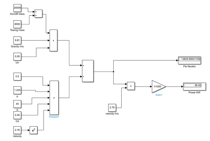
7. A. Design an electric powertrain with type of motor, it’s power rating, and energy requirement to fulfill aircraft towing application in Simulink. Estimate the duty cycle range to control the aircraft speed from zero to highest. Make all required assumptions. Prepare a table of assumed parameters. Draw a block diagram of powertrain.
(Hint :DC7 Block)
According to assumed & calculated values for towing an aircraft of 20000 kg needed 38.30kW of power.
Lets consider Aircraft is to be tow by Towing vehicle for 20minutes, There energy required will be,
Energy required, E= Required power * time
E=38.30*(20/60)
E= 12.77kWH
So we require to select a motor for towing vehicle which can take this much power to push/pull the aircraft.
Lets consider Efficiency of transmission system to be 85% considering transmission losses, Therefore Motor Power required will be, 38.30 / 0.85
Motor power =45.05kw
Lets consider Vehicle Drive:50 kW, 200 V DC Traction Motor
Power Output= 50 kW
Battery Current= Power/ Voltage
Battery Current= 50kW/200V
Battery Current=250Ah
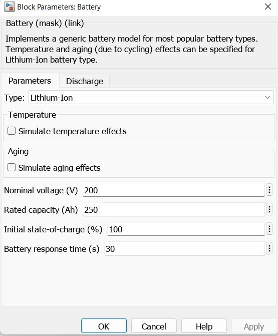
Batteries: 200 VDC , 250 AMP-HR Battery.
Duty Cycle= Calculated power/ Required power
Duty Cycle= 38.30/50
Duty Cycle= 0.766
% Duty Cycle=76.60%
Simulink Model-
The below model represents the simple model for powertrain model for aircraft towing vehicle on runways. The block set consist of Battery source, 4-quadrant chopper (DC7 Block) , motor, controller & converter.
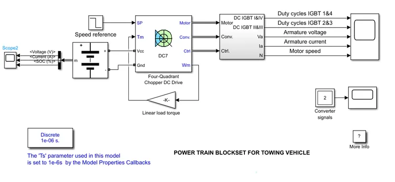
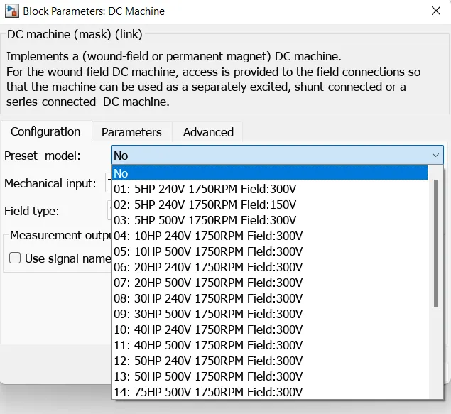
Here DC 7 block is been used for Four quadrant chopper operation. DC 7 block allows us to select the Motor preset model, Convereter & controller.
Based upon the calculations the Battery value was selected to be of 200V, 250Ah. The DC7 block is feed with a 200V battery source.
The first regulator is a speed regulator followed by a current regulator. The speed regulator outputs the aramature current used by current controller in order to obtain electromagnetic torue needed to reach desired speed. The speed reference change the raye follows acceleration & deceleration ramps in order to avoid sudden reference changes that could cause armature over current & destabilize the system.
Results-
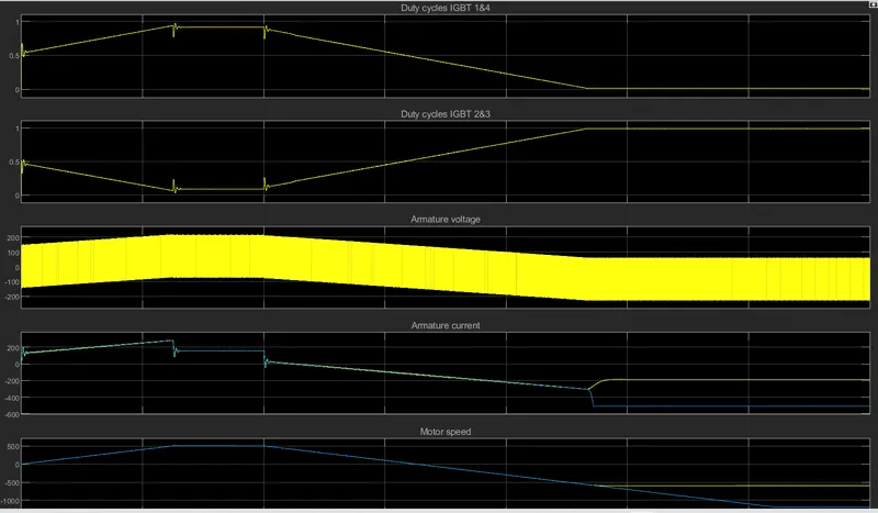
The plot consists of Duty cycles of IGBT Switches,
Armature voltage of motor,
Armature Current of motor
& Motor speed.
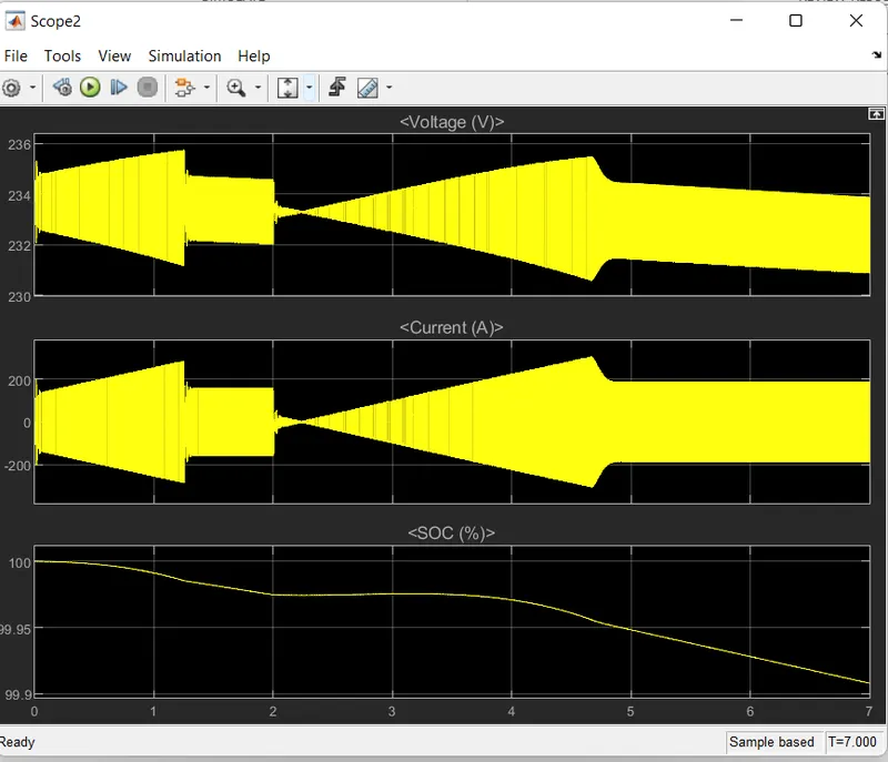
Battery scope block showing Battery Voltage, current & state of charge (soc).
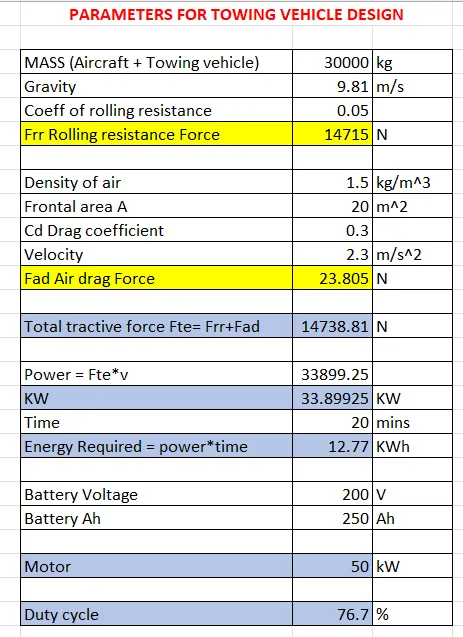
B. Also, Design the parameters in excel sheet.
Conclusion-
listed out the total weight of various types of aircrafts.
Application of Towing machine on aircraft runways.
Force & Power calculations for Towing vehicle for push/pull the aircraft on runway.
4 quadrant chopper using DC7 block for powertrain blockset of towing vehicle.