Project-1: Powertrain for aircraft in runways
Part-A
Task-1:
Total weight of various types of air craft:
The Various types of Aircrafts are Aeroplanes, Helicopters, Airship, Glider, Convertiplane etc.
At the time of releasing its brakes, the gross weight of an aircraft is equal to its take-off weight. During flight, an its gross weight is referred to as the en-route weight or in-flight weight. An aircraft's gross weight is limited by several weight restriction. To avoid overloading its structure or to avoid unacceptable performance or handling qualities while in operation aircraft gross weight limits are established during an aircraft's design and certification period.
Considering the MTOW (maximum Take-off weight) is the maximum weight of an aircraft included all the weights (cargo, passengers, fuels, etc.). MTOW is always greater than the MLW (maximum landing Weight).
Aeroplanes: Aeroplanes come in a variety of sizes, shapes, and wing configuration. The broad spectrum of uses for airplanes includes recreation, transportation of goods and people, defence , and research.
|
S.no |
Type of air craft |
MTOW(Kg) |
|
1 |
Antonov An-225 |
640000 |
|
2 |
Airbus A380-800 |
575000 |
|
3 |
Boeing 747-8F |
447700 |
|
4 |
Boeing 747-8 |
443613 |
|
5 |
Lockheed C-5 Galaxy |
381000 |
|
6 |
Boeing 747-100 |
340200 |
|
7 |
Boeing 777-300 |
299370 |
|
8 |
Airbus A350-1000 |
308000 |
|
9 |
McDonnell Douglas MD-11 |
273300 |
|
10 |
Ilyushin II-96M |
270000 |
|
11 |
Concorde |
185000 |
|
12 |
Vickers VC10 |
152000 |
|
13 |
Tupolev Tu-154M |
104000 |
|
14 |
Convair 880 |
87500 |
|
15 |
De Havilland Comet 4 |
70700 |
|
16 |
Hawker Siddeley trident 2E |
65000 |
|
17 |
Douglas DC-7 |
55000 |
|
18 |
Embraer 190 |
48000 |
|
19 |
Caravelle III |
46000 |
|
20 |
Bombardier CRJ200 |
23000 |
|
21 |
ATR 72-600 |
22800 |
|
22 |
Saab 2000 |
22800 |
|
23 |
Bae Jetstream 41 |
10890 |
|
24 |
Learjet 75 |
9752 |
|
25 |
Pilatus PC-24 |
8300 |
|
26 |
Beechcraft 1900D |
7765 |
|
27 |
Cesna Citatin CJ4 |
7761 |
Helicopters:
A helicopter, sometimes referred to in slang as a "chopper" or "helo" is a type of rotorcraft in which lift and thrust are supplied by horizontally-spinning rotors. This allows the helicopter to take off and land vertically, to hover, and to fly forward, backward, and laterally.
|
S.no |
Type of air craft |
MTOW(Kg) |
|
1 |
Mil Mi -12 |
231485 |
|
2 |
Mil Mi-26 |
123459 |
|
3 |
Sikorsky S-92 |
26500 |
|
4 |
Eurocopter AS532 Cougar |
19840 |
|
5 |
Airrbus Helicopter H160 |
13340 |
|
6 |
Bell 412-EP |
11900 |
|
7 |
AeroVelo Atlas |
282 |
Convertiplane:
A convertiplane is defined by the Fédération Aéronautique Internationale (FAI or World Air Sports Federation) as an aircraft which uses rotor power for vertical take-off and landing (VTOL) and converts to fixed-wing lift in normal flight. In the US it is further classified as a sub-type of powered lift.
|
S.no |
Type of air craft |
MTOW(Kg) |
|
1 |
Bell Boeing V-22 Osprey |
27445 |
|
2 |
Bell-Agusta BA609 |
7600 |
|
3 |
Bell XV-15 |
6009 |
Glider:
A glider is a fixed wing aircraft that is supported in flight by the dynamic reaction of the air against its lifting surfaces, and whose free flight does not depend on an engine. Most gliders do not have an engine, although motor glider have small engines for extending their flight when necessary by sustaining the altitude (normally a sailplane is on a continuously descending slope) with some being powerful enough to take off self-launch.
|
S.no |
Type of air craft |
MTOW(Kg) |
|
1 |
DG Flugzeugbau DG-800 |
156 |
|
2 |
Sandlin goat |
70 |
|
3 |
Waco CG-4A |
1769 |
Airship:
An airship or dirigible balloon is a type of aerostat or lighter-than-air aircraft that can navigate through the air under its own power. Aerostats gain their lift from a lifting gas that is less dense than the surrounding air. Airships were the first aircraft capable of controlled powered flight, and were most commonly used before the 1940s; their use decreased as their capabilities were surpassed by those of aeroplanes.
|
S.no |
Type of air craft |
MTOW(Kg) |
|
1 |
Zeppelin NT D-LZZF |
6622 |
|
2 |
Bodensee |
13646 |
|
3 |
R101 |
133229 |
Task:2
there are two different types of speed when talking about airplanes – ground speed and airspeed.
While ground speed is the airplane’s speed relative to the surface of the Earth,airspeed – is its speed relative to the air it is flying in.
Airspeed vs. Ground Speed:
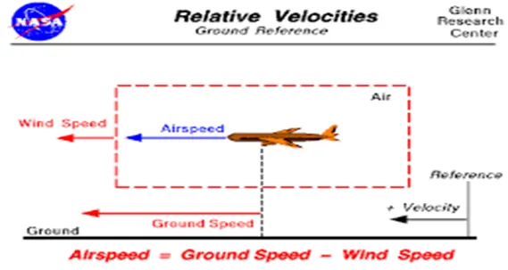
Airspeed is simply the speed at which an aircraft is moving relative to the air it is flying in. As such, it’s also the speed at which the air is flowing around the aircraft’s wings.
Ground speed, on the other hand, is the aircraft’s speed relative to the ground. One thing that should be noted here is that it’s its horizontal rather than vertical speed – an aircraft climbing completely vertically would have a ground speed of zero.
while airspeed is what determines whether there is enough airflow around an aircraft to make it fly, ground speed is what determines how fast an aircraft will get to its destination.
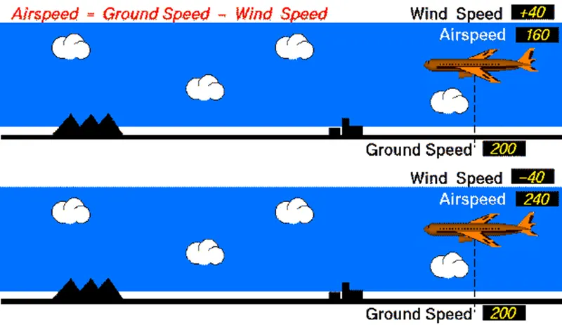
The relationship between airspeed and ground speed is fairly simple. Ground speed is simply the sum of airspeed and wind speed.
If the aircraft is flying in the same direction as the wind is blowing, the aircraft experiences tailwind, and its ground speed is higher than its airspeed. On the other hand, if the wind is blowing against the direction the aircraft is traveling in, the aircraft experiences headwind, and its ground speed is lower than its airspeed.
Task:3
Aircraft engine power to move it on the ground at Airport is not recommended.
Because of the Unwanted consequences may possible from the unintended movement of the aircraft during engine running.
- Effectively a loss of control can happen, especially during high power engine running. Damage can occur to the aircraft itself, other aircraft nearby or to airside structures.
- There is a risk of injury to ground support personnel who may be in relatively close proximity to the aircraft.
- It is easier for truck driver to see the surroundings better than the pilot sitting in the cockpit with limited window. The pushback driver knows the airport better than the pilot.
- It also saves fuel. virgin Atlantic had proposed a new system in which pushback truck will move the aircraft all the way to runway to save fuel and reduce impact of environment.
- The plane engines are very loud. When more than one plane will add up their sound, than it will not be pleasant for passengers and others near airport.
Therefore, there are pushback trucks in the airport. A pushback truck lifts the front wheel of the aircraft, their role in most airports is to move the aircraft away from the parking spot on to the taxiways, which is called towing.
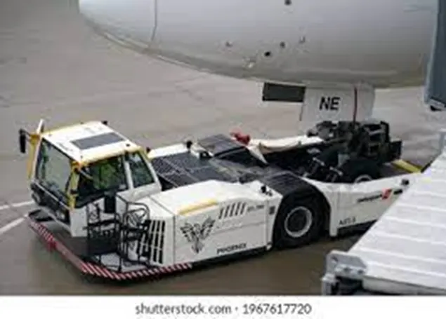
For movement on the ground the aircraft uses it own engine power, which is called taxing.
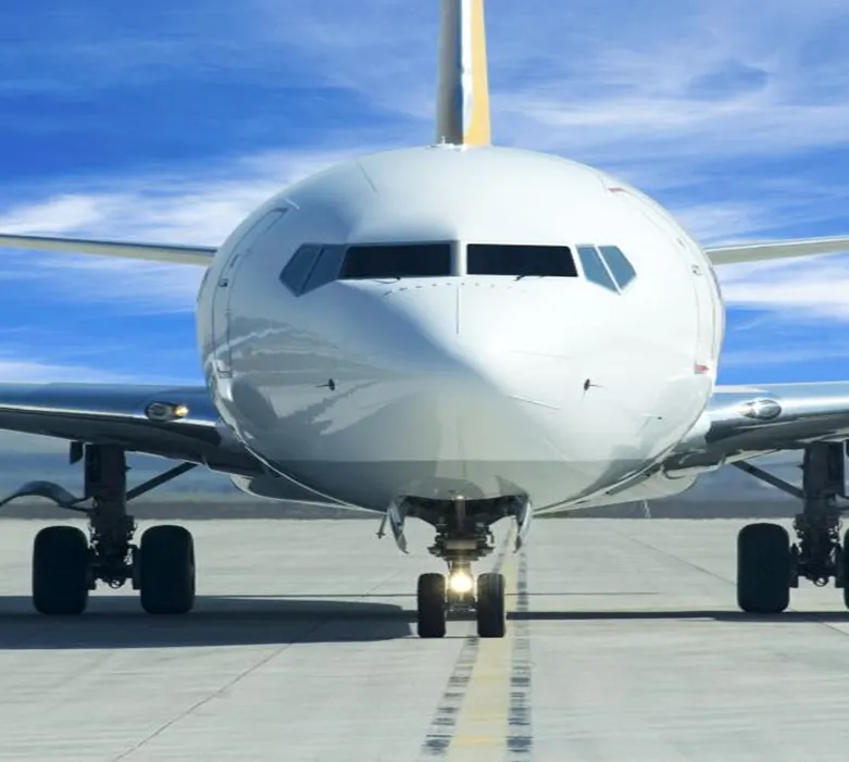
Taxiing (rarely spelled taxying) is the movement of an aircraft on the ground, under its own power, in contrast to towing or pushback.
Task:4
TOWING:
A pushback truck lifts the front wheel of the aircraft, their role in most airports is to move the aircraft away from the parking spot on to the taxiways, which is called towing. The towing is a process in aircraft operations. To move aircraft from one place to another place after landed. Which may be run way to parking hanger or run way to maintenance hangar. Here is clear, that towing is the key part to move aircraft at ground.
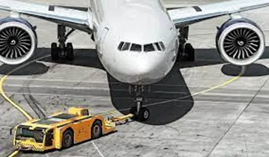
Above picture shows the towing of aircraft from parking slot to taxiing.
Taxiing:
Taxiing (rarely spelled taxying) is the movement of an aircraft on the ground, under its own power, in contrast to towing or pushback. The aircraft always moves following the yellow lines, to avoid collision with the surrounding buildings, vehicle or other aircrafts. The taxiing motion has a speed limit. Before making turn the pilot reduces speed further to prevent tire skids just like other vehicles. The reason for taxing is to reach the vehicle into runway or from runway to terminal.
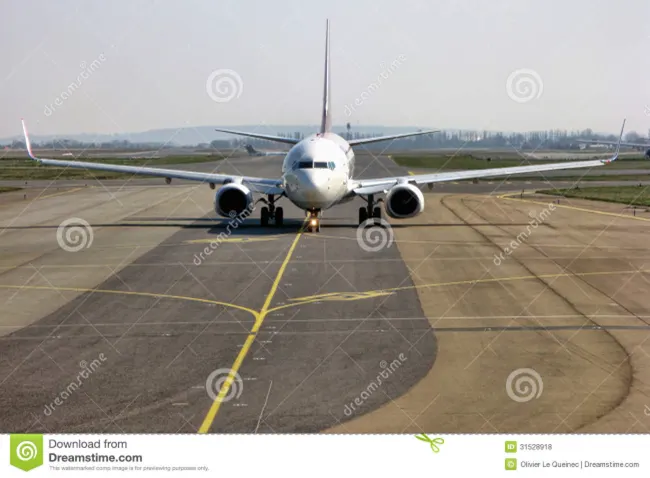
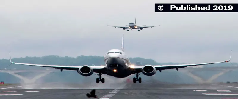
Following the taxiway aircraft reaches the runway. Take-off is the phase of flight in which an aircraft goes through a transition from moving along the ground (taxiing) to flying in the air, usually starting on a runway. Usually, the engines are run at full power during take-off. Following the taxi motion, the aircraft stops at the starting line of the runway. Before take-off, the engines, particularly piston engines, are routinely run up at high power to check for engine-related problems. This makes a considerable noise. When the pilot releases the brakes, the aircraft starts accelerating rapidly until the necessary speed for take-off is achieved.
Task:5
Take-off power:
Take-off is the phase of flight in which an aircraft leaves the ground and becomes airborne. For aircraft that take off horizontally, this usually involves starting with a transition and moving along the ground on a runway. For light weight aircraft, usually full power is used during take-off. Large transport catagory (airliner) aircraft may use a reduced power for take-off, where less than full power is applied in order to prolong engine life, reduce maintenance costs and reduce noise emissions. In some cases, the power used can then be increased to increase the performance. Before take-off, the engines, particularly piston engines are routinely run up at high power to check for engine-related problems.
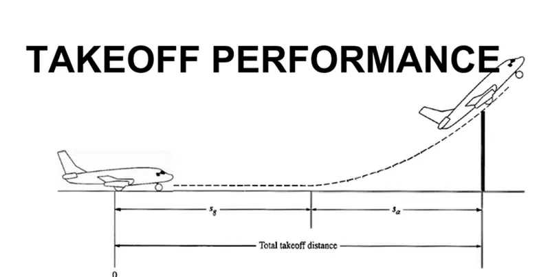
An airplane is motionless at the starting of a runway. This is denoted by location O. The pilot releases the brakes and pushes the throttle to maximum take-off power, and the airplane accelerates down the runway. At some distance from its starting point, the airplane lifts into the air. The distance the airplane cover along the runway before it lifts into the air is called the ground roll (sg). The total take-off distance also includes the extra distance covered over the ground after the airplane is airborne but before it clears an obstacle of 50 ft for military aircraft and 35 ft for commercial aircraft. This is denoted by sa. The sum of sg and sa is the total take-off distance.
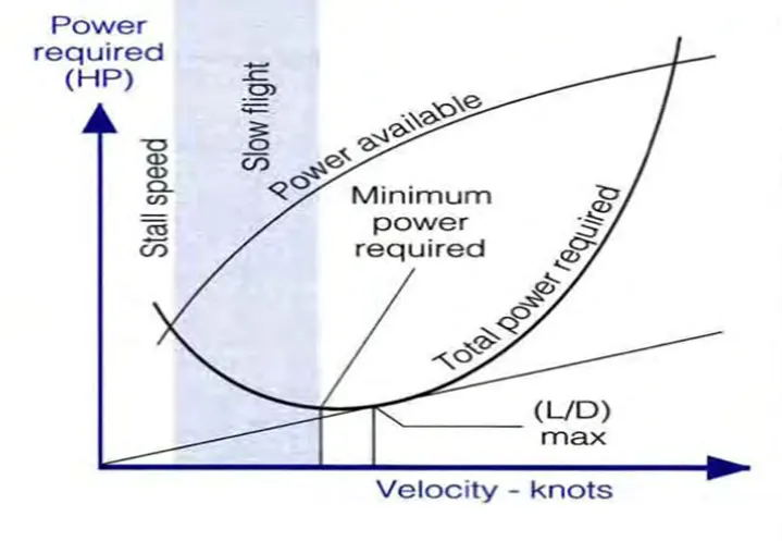
Figure above shows the "power curves”. The slower one flies the less air is diverted and thus the angle of attack must be increased to increase the vertical velocity of that air. Pilots practice flying on the "backside of the power curve" so that they recognize that the angle of attack and the power required to stay in the air at very low speeds are considerable.
Tyre Design:
An aircraft tire is designed to withstand extremely heavy loads for short duration of time. The number of tires required for aircraft increases with the weight of the aircraft, as the weight of the airplane needs to be distributed more evenly. For example -A Boeing 737NG & 737MAX uses 6 wheels, Boeing 787 uses 10 wheels, Boeing 777 uses 14 wheels and Airbus A380 uses 22 wheels.
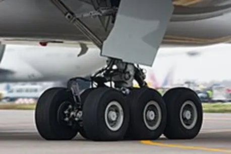
Aircraft tires also include fusible plugs (which are assembled on the inside of the wheels), designed to melt at a certain temperature. Tires often overheat if maximum braking is applied during an aborted take-off or an emergency landing. The fuses provide a safer failure mode that prevents tire explosions by deflating in a controlled manner, thus minimizing damage to aircraft and objects in the surrounding environment.
Designing aircraft tires is a very intense undertaking. Carcass plies are used to form the tire. They are sometimes called casing plies. An aircraft tyre is constructed for the purpose it serves.
- They support the weight of an aircraft while it is on the ground.
- It also provides the necessary traction for braking and stopping of an aeroplane.
- Tyre also helps to absorb the shock of landing and provide cushioning the roughness of take-off, roll-out, and taxi operations.
Once an aircraft manufacturer goes to the tire manufacturer with the size and weight requirements, the tire manufacturer begins the process of designing a tire that meets the needs of the aircraft manufacturer as well as all regulatory requirements — including foreign regulations in many cases. Engineers are challenged with designing tires with cool running, heat-resistant materials while simultaneously exceeding tire service requirements.
Two types of tires are used in aircraft applications-1. bias-ply tires and 2.radial tires. Although both types of tires share some similarities in design, there are difference between a radial tyre and bias (cross-ply) tyre is the lay of the plies within the tyre carcass. The remainder of the tyre is very similar in construction in both.
Bias-Ply tires:
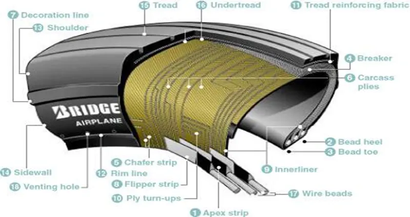
|
1. Apex strip: |
Radial tires:
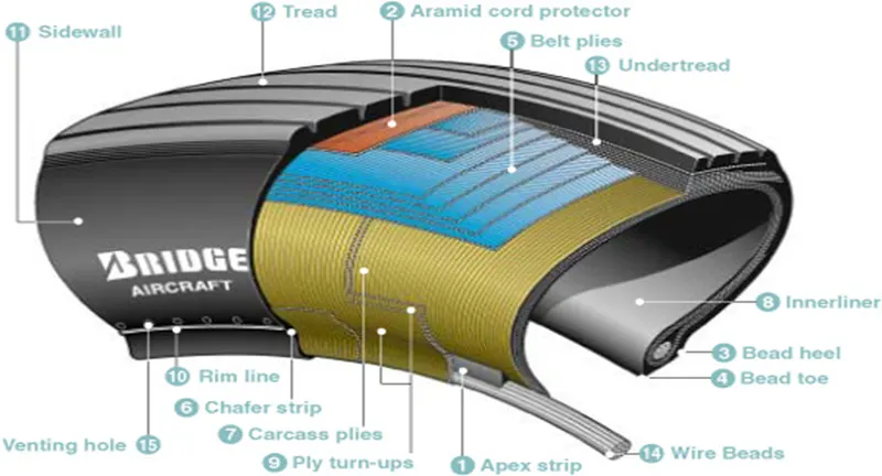
1.Apex strip:
A triangular piece of stiff rubber which is fitted onto the bead core to taper the rigid bead into the flexible body plies in the sidewall.
2. Aramid cord protector:
The tire is constructed with an aramid ply insert between the tread and the top belt to prevent damage to the tire belts.
3. Bead heel:
Outer edge of the bead.
4. Bead toe:
Inner edge of the bead.
5. Belt plies:
Angled belt plies which serve to add strength to the tire especially in the tread area.
6. Chafer strip:
Protective layer of rubber and fabric which prevents chafing between cord body plies and the wheel.
7. Carcass plies:
Layers of rubber-coated fabric plies which have the cords running radially from bead to bead. These provide the tire with strength in the sidewall area.
8. Innerliner:
A sheet of low permeable rubber laminated to the inside of the first casing ply of a tubeless tire to insure retention of air when tire is inflated.
9. Ply turn-ups:
The turned-up ends of plies around the bead. Other plies lock the ends into place.
10. Rim line:
A line provided near the beads to allow inspection of how the tire fits with the rim.
11. Sidewall:
The side area of the tire located between the shoulder and the beads. Composed of rubber, it protects the carcass from damage.
12. Tread:
The functions of the radial tread are the same as those defined for the bias tire.
13. Undertread:
A rubber layer provided for use in retreading the tire and which provides adhesion of tread to the tire carcass. Bridgestone makes this rubber layer thick enough to ensure a high number of retreads.
14. Wire beads:
Two wire bundles (one for each bead) which help to maintain the shape of the tire and anchor it securely to the rim.
15. Venting hole:
The hole through which gas is vented from inside the carcass plies.
Rolling Resistance:
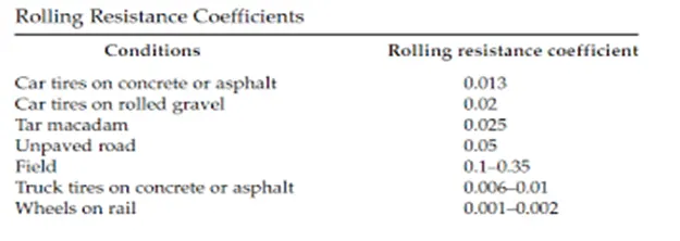
In addition to the familiar forces like thrust, weight, lift, drag there is a rolling resistance force Fr. caused by friction between tyre and ground. When aircraft is towing or taxing to pushed it into runway or when take-off roll is happening, the rolling resistance force act against the traction force of the aircraft.
This rolling resistance force depends on many factors like surface of the road, roughness of the road, dry or wet condition of the road, tyre pressure, tyre material, tyre temperature, thread pattern of the tyre etc, which determines the rolling resistance force.
Rolling resistance is denoted by Frr
Frr = M*g*mrr
M is the vehicle; g is the gravitational force; mrr is coefficient of rolling resistance.
Tyre Pressure:
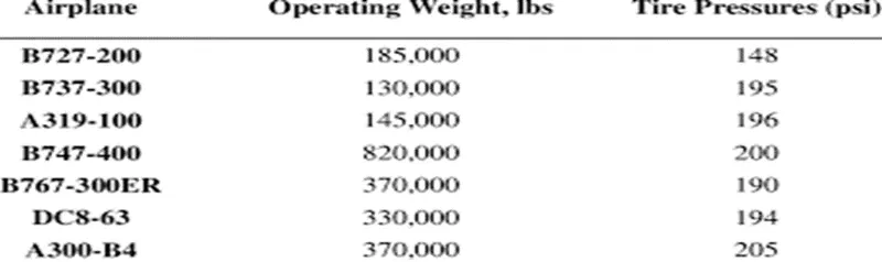
The pressure generally is very high in an aircraft tire to reduce the rolling resistance and to withstand the weight. Usually, the tyre pressure will be around 190 to 320 psi based on the type of aircraft. Aircraft tyres are usually inflated with nitrogen to minimize expansion and contraction from extreme changes in ambient temperature and pressure experienced during flight.
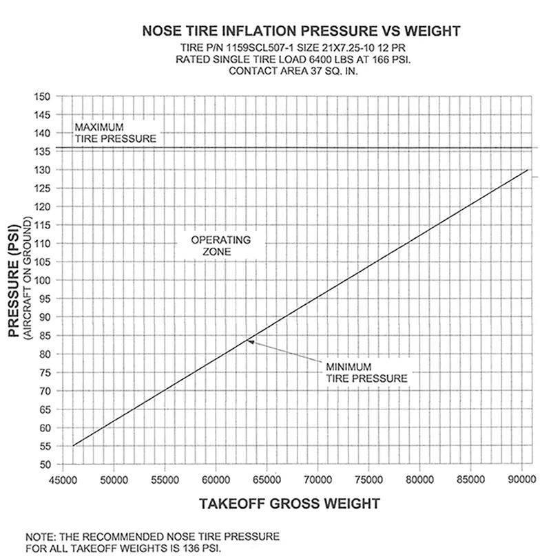
According to U.S. Federal Aviation Administration (FAA) Technical Standard Order TSO-C62c, the maximum allowable tire pressure loss is 5% per day.
Example:
A Boeing 777 fully loaded weighs around 700,000 pounds and has fourteen tires. Therefore, if each of those tires is reacting roughly the same force, then that is 50,000 pounds per tire. The tire pressure is 200 psi. Therefore there should be 250 square inches of surface contact area for each tire with the ground (250 * 200 = 50,000).
Brake forces while landing:
Stopping an aircraft landing at 180-200 mph requires a lot of braking force. To do this, the aircraft has brake unit on each of the wheels on the main gear assembly. On landing, pilots should use aerodynamic braking by applying extra back-pressure on the stick or yoke. Extreme caution should be used when applying brakes at any significant speed, and only when the end of the runway is quickly approaching. Never step on the brakes to make a runway exit. Applying the brakes at too high a speed could burn the tires, wear out the brakes, or result in a ground loop or swerve.
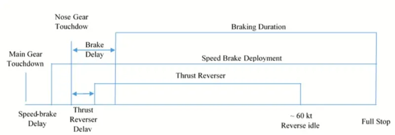
Aircraft braking systems include:
1.Aircraft Disc Brake: In the landing gear it is used to brake the wheels while touching the ground. These brakes are operated hydraulically. In most modern aircraft they are activated by the top section of the rudder pedals ("toe brakes"). In some older aircraft the bottom section is used instead ("heel brakes"). Levers are used in a few aircraft. Most aircraft are capable of differential braking.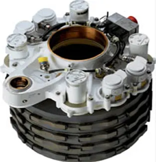
2.Air Brake: It is dedicated flight control surface, that work by increasing drag.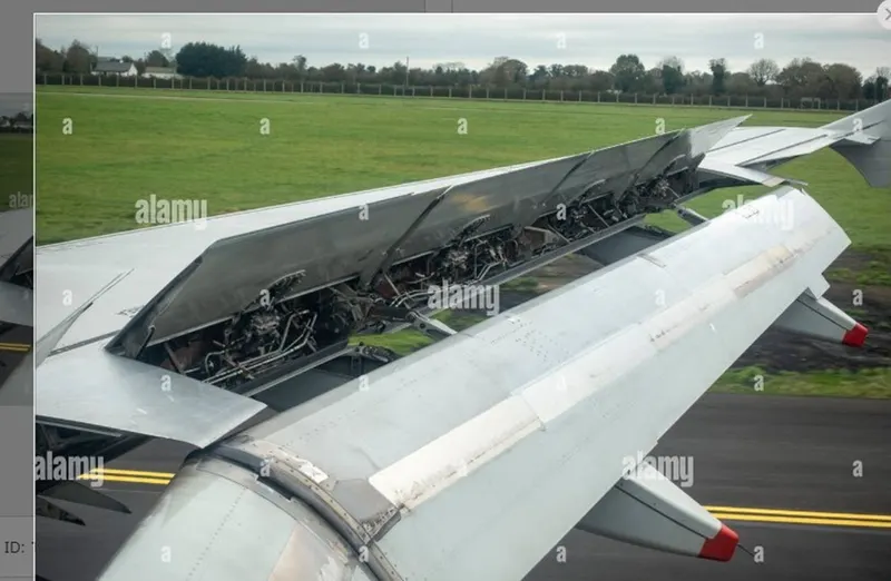
3.Thrust Reverse: that allow thrust from the engines to be used to slow the aircraft.
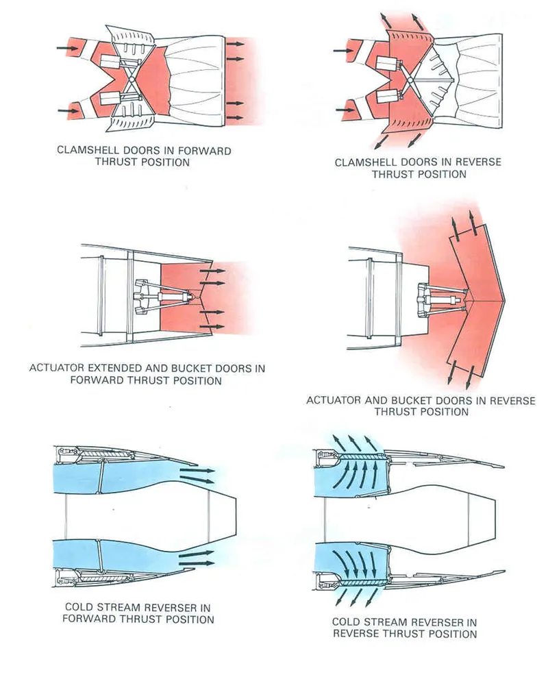
4.Drogue Parachute: It is used by several former and current military and civilian aircraft (examples include the American B-52 and the soviet Tu-134 and Tu-144).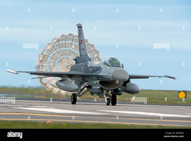
Part-B
TASK:6
push or pull an aircraft by a towing vehicle, 3 type of forces will act on that vehicle.
- Rolling resistance force
- Aerodynamic force
- Hill climbing force
1.Rolling resistance force (Frr):
Rolling resistance is the force resisting the motion when a body rolls on a surface. It is the friction force that is needed to be overcome to move a vehicle. The kinetic energy of the wheels is partially converted into heat. The rolling resistance is proportional to the normal force perpendicular to the rolling wheel and is approximated by the rolling resistance coefficient mrr. Therefore, Equation that can be used for the rolling resistance force of the entire system is
Frr =M*g*mrr
Where: mrr is rolling resistance co-efficient (depends on tire material, tire structure, road roughness, road material etc.), M is total mass of the vehicle, g is gravitational constant, that is 9.8 m/s^2.
Consider the mrr of towing vehicle is 0.002 and Aircraft is 0.005
2.Aerodynamic force (Fad):
Aerodynamic drag force is the force which is required to keep a vehicle moving. There are two components of this force, one is shape drag (due to the shape of the vehicle) and another is skin friction (due to friction between air and skin of the vehicle). When the vehicle moves the velocity of air near boundary is higher than the air surrounding. Both the tug and the aircraft will experience some aerodynamic drag. For completeness, the aerodynamic drag force caused by the aircraft and towing vehicle can be given by Equation below.
Fad = (1/2) * ρ * V^2 * A * Cd
where, ρ = Air density, that is normally 1.25 kg/m^3, V = Velocity m/s, A=frontal area M^2,
Cd is drag coeffiecient.
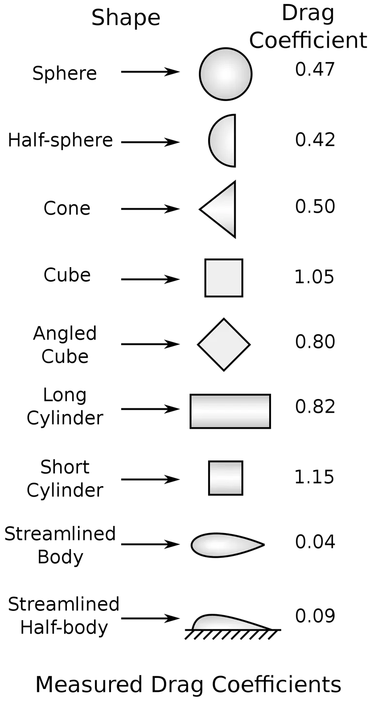
In this case, we consider drag coefficient of both towing vehicle and aircraft
Drag coefficient of towing vehicle (CdT) =0.6 and
Drag coefficient of aircraft (CdA) =0.12
Due to zero inclination angles , hill climbing force is neglected.
Push/pull power calculation of towing vehicle:
Let’s assume,
Mass of towing vehicle is 30000 kg’s
Mass of aircraft is 183500 Kg’s
Total Mass is (towing +aircraft) = 30000+183500 = 213500 kg’s
Rolling resistance coefficient of aircraft = 0.005
Rolling resistance coefficient of towing vehicle = 0.002
Air drag of Towing vehicle =0.6, Aircraft =0.12
Air density =1.25 Kg/M^3
Towing vehicle frontal area = 40 M^2
Aircraft frontal area = 300 M^2
Total frontal area = 340 M^2
Speed of the vehicle =10 km/hr = 2.77 m/sec.
Rolling resistance force(Frr) for aircraft = M*g*mrr = 183500*9.81*0.005 = 9000.67 N
Rolling resistance force(Frr) for towing vehicle = M*g*mrr = 30000*9.81*0.002 = 588.6 N
Total Frr =9000.67 + 588.6 = 9589.27
Aerodynamic force (Fad) for Aircraft = (1/2) * ρ * V^2 * A * Cd = 0.5* 1.25*(2.77) ^2 *300* 0.12
= 172.64 N
Aerodynamic force (Fad) for Towing vehicle = (1/2) * ρ * V^2 * A * Cd = 0.5* 1.25*(2.77) ^2 *40* 0.6
= 115.09 N
Total Fad = 172.64 + 115.09 = 287.73 N
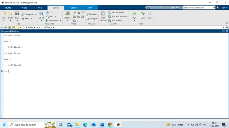
Total force = Frr +Fad = 9589.27 + 287.73 = 9877 N = 9.87 K N
Total power = Total force * speed = 9.87 * 2.77 = 27.34 KW
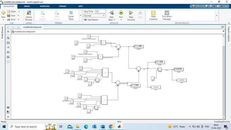
Model for calculating force and power:
MATLAB script:
% model for calculating vehicle force and power%
%rolling resistance force (Frr)%
M = 183500; % mass of aircraft in kg's %
M1 = 30000 % Mass of towing vehicle in Kg's%
g= 9.81 ; % gravitational force m/s^2%
mrr = 0.005; %coefficient of rolling resistance for air craft%
mrr1 = 0.002; %coefficient of rolling resistance for towing vehicle%
% Aerodynamic force%
P = 1.25; % air density ,kg/M^3%
Cd =0.12; % %air drag coefficient for aircraft%
Cd1 =0.6; % %air drag coefficient for towing vehicle%
A= 300; %aircraft frontal area,M^2%
A1= 40; % towing vehicle frontal area,M^2%
V=10; %velocity in Km/h%
v=V/3.6; % velocity in m/s%
Simulink model:
Output:
TASK:7
|
Assumptions of power train design |
|
|
Aircraft Mass |
183500 Kg |
|
Towing Vehicle Mass |
30000 Kg |
|
Rolling Resistance Co-efficient for aircraft |
0.005 |
|
Rolling Resistance Co-efficient for towing vehicle |
0.002 |
|
Air Density |
1.25 kg/m^3 |
|
Aircraft Drag Co-efficient |
0.12 |
|
Towing Vehicle Drag Co-efficient |
0.6 |
|
Frontal area for aircraft |
300 m^2 |
|
Frontal area |
40 m^2 |
|
Inclination Angle |
0 rad |
|
Tyre Pressure |
203 PSI/14 bar |
|
Towing Velocity(V) |
10km/h =2.778m/s |
|
Towing Time(t) |
10 min |
|
Radius of the |
0.7 m |
|
Overall gear ratio |
7 |
|
Transmission efficiency |
80% |
|
Motor efficiency |
92% |
Therefore, from the excel power calculator we have got the necessary Traction force(F) quantity that is 9.87 K N and power required is 27.34 KW
We known that torque required at wheels, Torque (T) = Force(F) * wheel radius(r) = 9.87* 0.7
T= 6.9 KN-m
Motor torque (Tm)= Wheel torque/(gear ratio* efficiency)
Tm = 6.9/(7*0.80)
(Assumed transmission efficiency= 80% and gear ratio = 7)
Tm= 6.9/5.6 = 1.23 KN-m
If the motor actual efficiency is 92%; then motor torque = 1.23/0.92 =1.33 KN-m
Power required by the motor will be; 27.34/ 0.92 = 29.71 KW ~= 30 KW
Required Energy(E) for towing application based on the assumed time, that is E=P*t
E= 30 *(600/3600) =30*0.166= 4.98 KWH
Now, we select the battery whose power rating is around 40 KW, so the duty cycle range to control the speed from zero to high speed is,
Duty cycle = output power/input power = 30 KW / 40KW = 0.75 =75%
Here the duty cycle range to control the speed 0 to 75%
For this application an Induction motor or a BLDC can be used with a proper gear system.
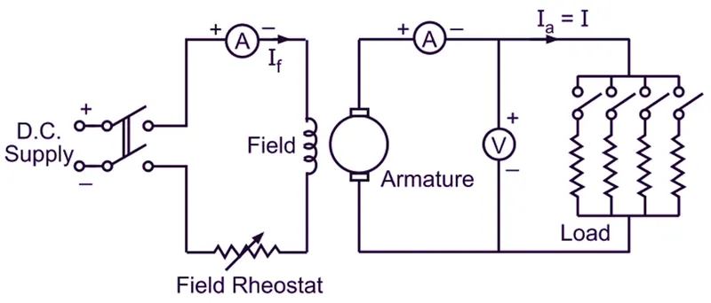
Considering, separately excited DC motor:
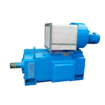
Circuit diagram of Separately excited DC motor:
DC motor nameplate details: for Separately excited DC motor
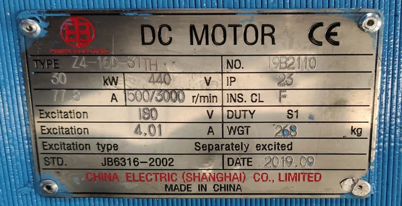
Consider, 30 KW DC motor Field voltage 440V and Excitation voltage 180V and Excitation Current is 4.01Amps. with Duty S1 means motor can run continuously (heavy duty).
Simulink model:
In this model, considering battery block , Four Quadrant motor controller and Dc motor under the mask of Four quadrant chopper Dc Drive.,Scope.
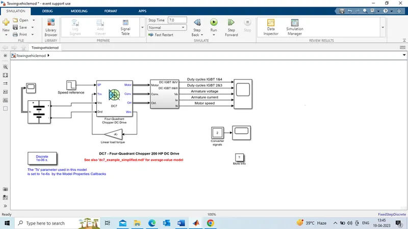
Output:

From the output, we can observe the Voltage applied to motor (field voltage) is 440 and motor speed is in RPM . IGBT controls over the four quadrants. Armature current follows the Duty cycle of IGBT's(1st and 4th).
parameters designed in excel sheet:
| TASK-7 | ||||
| Assumed parameters | ||||
| Aircraft (Ac) weight | 183500 | kg | 213500 | |
| Towing vehicle weight(Tv) | 30000 | kg | ||
| Coefficient of rolling resistance(Ac) | 0.005 | |||
| Coefficient of rolling resistance(Tv) | 0.002 | |||
| gravitational force | 9.81 | m/S^2 | ||
| Rolling resistance force (Ac) | 9000.675 | N | ||
| Rolling resistance force (Tv) | 588.6 | N | ||
| Rolling resistance force(Frr) | 9589.275 | N | ||
| Air density | 1.25 | kg/m3 | ||
| drag coefficeint(Ac) | 0.12 | mts | ||
| drag coefficeint(Tv) | 0.6 | mts | ||
| Frontal Area(Ac) | 300 | M^2 | ||
| Frontal Area(Tv) | 40 | M^2 | ||
| speed | 2.77 | m/s | ||
| constant | 0.5 | |||
| Air drag force(Ac) | 172.64025 | N | ||
| Air drag force(Tv) | 115.0935 | N | ||
| Air drag force(Fad) | 287.73375 | N | ||
| Hill climbing angle | 0 | degree | ||
| Hill climbing force | 0 | |||
| Total force(Frr+Fad) | 9877.00875 | N | ||
| total power (Force*speed) | 27359.31424 | W | ||
| Towing vehicle speed | 10 | kmph | ||
| towing time | 10 | min | 600 | sec |
| Radius of towing vehicle wheel | 0.7 | m | ||
| Overall gear ratio | 7 | |||
| Transmission efficiency | 80 | % | 0.8 | |
| motor efficiency | 92 | % | 0.92 | |
| tyre pressure | 203 | psi | ||
| Torque required at wheels | 6913.906125 | N-m | ||
| Motor torque(In terms of Transmission efficiency) | 1234.626094 | N-m | ||
| Motor torque (in terms of motor effieciency) | 1341.984885 | N-m | ||
| Power required by the motor | 29738.38504 | W | 30000 | Approx |
| Required energy | 4956.397507 | WH | ||
| Consider battery power | 40000 | W | ||
| Duty cycle | 0.75 | 75% | ||
| Here , the duty cycle range to control towing vehicle speed from 0 to 75% | ||||