Project-1: Powertrain for aircraft in runways
Part A:
1. Search and list out the total weight of various types of aircrafts.
Ans:
| Type of aircraft | Max takeoff weight(Kg) | Max landing weight(Tonnes) | Weight class |
| Airbus A340-500 | 371,950 | 240 | Heavy |
| Boeing 757-300 | 124,000 | 101.6 | B757 |
| Airbus A320-100 | 68,000 | 66 | Large jet |
| Bombardier CRJ900 | 36,500 | 33.345 | Large commuter |
| Embraer 120 Brasilia | 11,500 | 11.25 | Medium |
| Cessna Citation CJ4 | 7,761 | 7.103 | Small |
2. Is there any difference between ground speed and air speed?
Ans:
Yes,
True airspeed is simply the speed at which an aircraft is moving relative to the air it is flying in. As such, it’s also the speed at which the air is flowing around the aircraft’s wings.
Ground speed, on the other hand, is the aircraft’s speed relative to the ground. One thing that should be noted here is that it’s its horizontal rather than vertical speed – an aircraft climbing completely vertically would have a ground speed of zero.
In other words, while airspeed is what determines whether there is enough airflow around an aircraft to make it fly, ground speed is what determines how fast an aircraft will get to its destination.
3. Why is it not recommended to use aircraft engine power to move it on the ground at Airport?
Ans:
Generally, aircraft move with the help of Engine power on the ground at the airport. The difference is that the engine power is not used at its full performance as obtained during the flight of the aircraft. The engine is operated under throttle 1 condition which uses engine power to obtain less speed. Sometimes it is not recommended to use the engine power to move the aircraft on the ground at Airport. There are multiple reasons for this one of which is that there are a lot of things as well as airport crew members surrounding the aircraft. If the aircraft uses its engine power in such an environment, the engine turbine or fan may suck or throw the surrounding objects, trash, or even human beings which is accidental.
The air intake of a jet engine is powerful enough to suck in human body. Even at a distance, the jet engine suction is strong enough to devour loose debris e.g., rags, bolts, paper, stones, catering foils, plastic cups, and bags. All these will damage the jet engine. In the case of Jet exhaust, the temperatures of the exhaust can severely burn the skin of a person standing too close. The jet blast or prop wash can exceed 100 mph and is capable of moving or toppling heavy persons or equipment. Other reasons are the noise of the engine which is at very high decibels as well as the fumes emitted by the burning of the fuel, the fuel consumption of an aircraft, and also the risk of damage to the engine due to foreign objects.
4. How an aircraft is pushed to runway when its ready to take off?
Ans:
There are two ways through which an aircraft is pushed to the runway in Airport.
Pushback – In aviation, pushback is an airport procedure during which an aircraft is pushed backward away from an airport gate by an external power. Pushbacks are carried out by special, low-profile vehicles called pushback tractors or tugs. Although many aircraft are capable of moving themselves backward on the ground using reverse thrust (a procedure referred to as a power back), the resulting jet blast or prop wash might cause damage to the terminal building or equipment. Engines close to the ground may also blow sand and debris forward and then suck them into the engine, causing damage to the engine. A pushback is therefore the preferred method to move the aircraft away from the gate. Closer to departure, an aircraft tug will park right in front of the nose wheel. The tug might be directly attached to the plane's nose gear with a tow bar, or could be a wheel-lift tug. These tugs cradle the nose gear, then lift it up before moving the plane. That gives the tug driver control over the plane's direction during pushback. New taxi technologies are appearing, like pilot-controlled tugs, and electric motors mounted to the plane's landing gear. Both promise to save fuel and reduce airport noise. When the aircraft is stopped, the brakes of the towing vehicle alone should not be relied upon to stop the aircraft. The man in the cockpit should coordinate the use of the aircraft brakes with those of the towing vehicle.
Taxiing is the movement of an aircraft on the ground, under its own power, in contrast to towing or push-back where the aircraft is moved by a tug. The aircraft usually moves on wheels, but the term also includes aircraft with skis or floats for water-based travel. An airplane uses taxiways to taxi from one place in an airport to another; for example, when moving from a hangar to the runway. The term taxiing is not used for the accelerating run along a runway prior to take-off, or the decelerating run immediately after landing, which is called the take-off roll and landing rollout, respectively. When taxiing, aircraft travel slowly. This ensures that they can be stopped quickly and do not risk wheel damage on larger aircraft if they accidentally turn off the paved surface. Taxi speeds are typically 30 to 35 km/h.
5. Learn about take-off power, tyre design, rolling resistance, tyre pressure, brake forces when landing.
Ans:
Take-off Power
The amount of power that an engine is allowed to produce for a limited period of time for takeoff. The use of takeoff power is usually limited to 5 min for reciprocating engines and up to 2½ min for gas turbine engines. This may not always be the case. Specifically, with respect to reciprocating engines, it is the brake horsepower developed under standard, sealevel conditions and under the maximum conditions of the crankshaft rotational speed and the engine manifold pressure approved for the normal takeoff. It is limited in continuous use to the period of time shown in the approved engine specifications. With respect to gas turbine engines, it is the thrust developed under static conditions at a specified altitude and atmospheric conditions of the rotor shaft rotational speed and gas temperature approved for the normal takeoff. It is limited in continuous use to the period of time shown in the approved engine specifications.
Tyre design
An aircraft tyre is designed to withstand extremely heavy loads for short durations. The number of tires required for aircraft increases with the weight of the aircraft, as the weight of the airplane needs to be distributed more evenly. Aircraft tire tread patterns are designed to facilitate stability in high crosswind conditions, to channel water away to prevent hydroplaning, and for braking effect. Aircraft tires also include fusible plugs(which are assembled on the inside of the wheels), designed to melt at a certain temperature. Tires often overheat if maximum braking is applied during an aborted takeoff or an emergency landing. The fuses provide a safer failure mode that prevents tire explosions by deflating in a controlled manner, thus minimizing damage to aircraft and objects in the surrounding environment.
Rolling resistance
when a tire rolls on the road, mechanical energy is converted to heat as a result of phenomenon referred to as rolling resistance. The term rolling resistance is often mistaken as a measure of the force opposing tire rotation, when instead is actually a measure of rolling energy loss.i in another terms we can say rolling resistance is the effort required to keep a given tire rolling. Its magnitude depends on the tire used, roughness of road, inflation pressure, load and speed. Generally rolling resistance is given by following formula
F = Cr ⋅ R
F = Rolling resistance force Cr = rolling resistance coefficient
R = Normal force between surface and tire
Tyre Pressure
Aircraft tires generally operate at high pressures, up to 200 psi (14 bar; 1,400 kPa) for airliners, and even higher for business jets. Tests of airliner aircraft tires have shown that they are able to sustain pressures of maximum 800 psi (55 bar; 5,500 kPa) before bursting. During the tests the tires have to be filled with water, to prevent the test room being blown apart by the energy that would be released by a gas when the tire bursts. Aircraft tires are usually inflated with nitrogen to minimize expansion and contraction from extreme changes in ambient temperature and pressure experienced during flight. Dry nitrogen expands at the same rate as other dry atmospheric gases (normal air is about 80% nitrogen), but common compressed air sources may contain moisture, which increases the expansion rate with temperature. The requirement that an inert gas, such as nitrogen, be used instead of air for inflation of tires on certain transport category airplanes was prompted by at least three cases in which the oxygen in air-filled tires had combined with volatile gases given off by a severely overheated tire and exploded upon reaching auto ignition temperature. The use of an inert gas for tire inflation eliminates the possibility of tire explosion.
Brake forces when landing
One of the effective parameters in fluencing landing run is the brake force, while it is ineffective during take-off operation. The airspeed during approach is decreased by increasing the angle of attack, but airspeed during ground roll is decreased by applying brakes. The mechanical brakes present at the wheels are of two common kinds; drum brakes and disc brakes. Drum brakes usually reside inside the wheel, which reduces their frontal area and, if mounted on retractable landing gear, makes them a possible solution for space-claim issues in thin wings. Disc brakes have superior performance, are lighter, and easier to maintain. The brake force is sometimes reinforced with other means such as parachute, engine thrust reversal, hook and string, and spoiler. These factors will reduce the landing run. The maximum aircraft angle of attack during landing is often 2°–4° less than the maximum aircraft angle of attack during take-off (e.g., 10°–15°). To compensate for this angle of attack reduction, a higher flap detection is employed. In most cases, flap detection during landing is between 30° and 60°, while during take-off it is between 5° and 30°.
Part B:
6. A. With necessary assumptions, calculate the force and power required to push / pull an aircraft by a towing vehicle.
Ans:
Assumptioms:
Lets consider the specifications of Toyota 3TE towing tractor and Airbus A320-100 aircraft.
1.Aircraft mass - 68000kg
2.Towing tractor mass - 2500kg
3.Push/Pull speed - 2m/s
4.Towing time - 25 seconds
5.Rolling coefficient between tyre and runway - 0.02
6.As the pulling speed is very low, we ignore the force required to overcome air drag
The total tractive force required to push / pull an aircraft by a towing vehicle
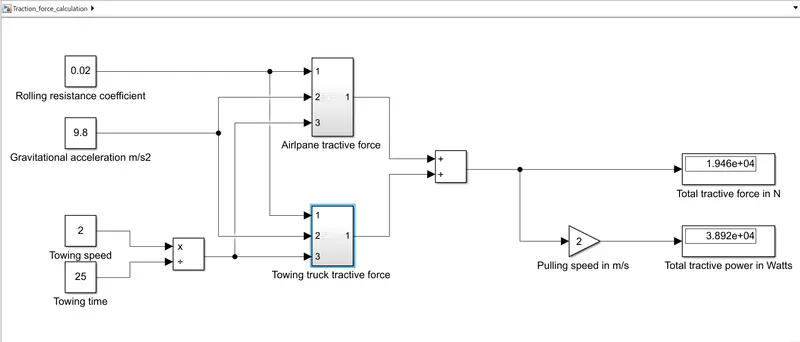
Ftrac = Ft+Fp
where,
Ft is tractive force required for the towing tractor alone
Fp is the tractive force required for the airplane
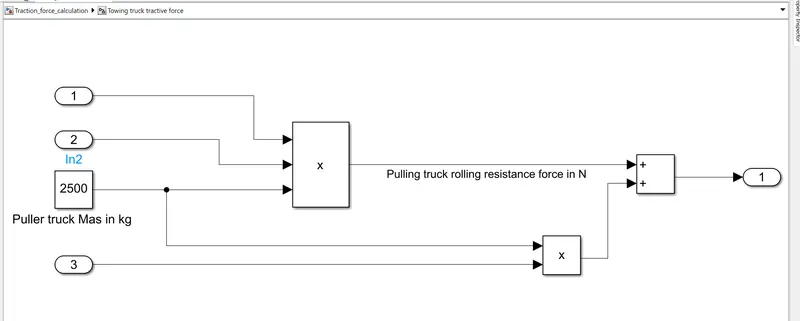
Ft = Rolling resistance force for towing vehicle + acceleration force
= (Rolling coefficient between towing vehicle tyre and runway * towing vehicle mass * accelerational gravity) + (towing vehicle mass * push or pull speed / towing time)
= (0.02 * 2500kg * 9.8mps) + (2500kg * 2mps/25s)
= 690N
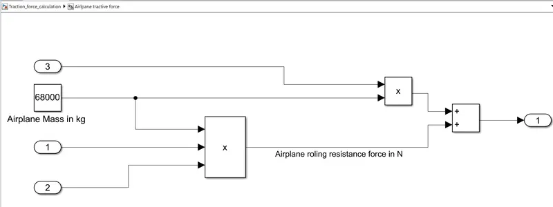
Fp = rolling resistance force for airplane + acceleration force
= Rolling coefficient between towing airplane and runway * airplane mass * accelerational gravity + (airplane mass * push or pull speed / towing time)
= (0.02 * 68000kg * 9.8mps) + (68000kg * 2mps/25s)
= 18768N
Hence total tractive force required, Ftrac = 690+18768 = 19458N
Total tractive power required, Ptrac = Ftrac * V = 19458 * 2 = 38,916 Nm/s ≈ 40KW
B. Develop the model for the calculated force and power using Simulink.
Ans:
Simulink model to calculate tractive force and power:
Q7. A. Design an electric powertrain with type of motor, it’s power rating, and energy requirement to fulfill aircraft towing application in Simulink. Estimate the duty cycle range to control the aircraft speed from zero to highest. Make all required assumptions. Prepare a table of assumed parameters. Draw a block diagram of powertrain.
Ans:
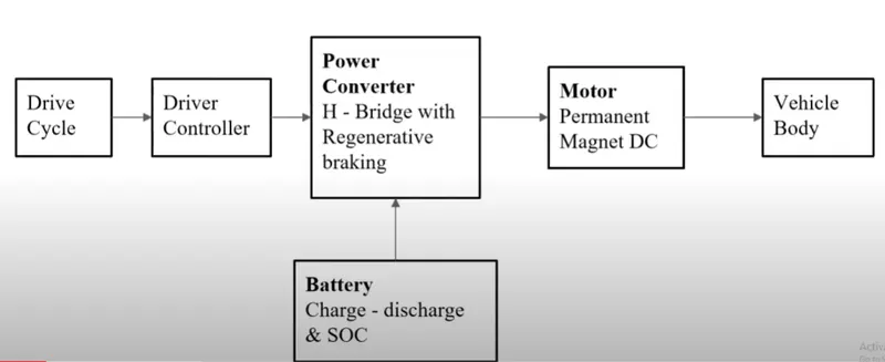
Block Diagram
Calculating Motor specifications:
From the above calculations, we found the total tractive force and the total tractive power required is 40KW
Therefore the torque required will be,
T = (Ftrac*r)/(G*ηg)
where,
r=wheel radius = 0.15m (assumed)
G=gear ratio = 25(assumed)
ηg = gear efficiency = 95%(assumed)
Motor torque, T = (Ftrac*r)/(G*ηg) = (19458*0.15)/(25*0.95) = 123Nm
Angular speed, ω = Pout/Tout = Ptrac/T = 40000/123 = 325 rad/sec = 325 * 9.55 = 3100 RPM
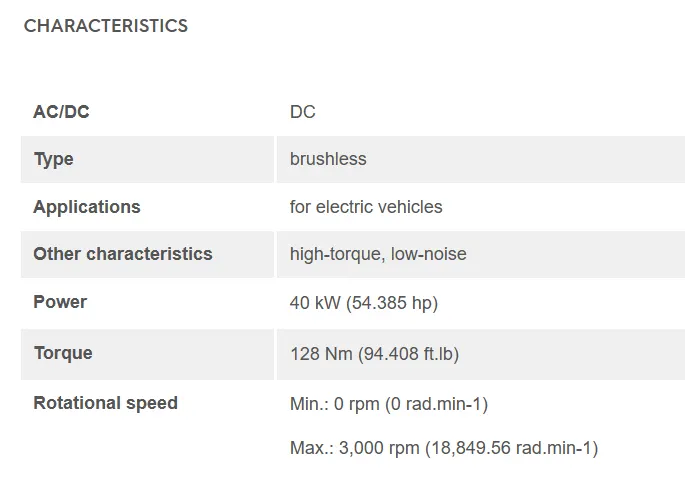
Considering above specifications we can go for below DC motor for our application


Battery Calculations:
Motor input power = Motor output power / Motor efficiency
Pin = Pout/motor efficiency
lets assume motor+controller efficiency is 80%
Therefore,
Pin = 40000/0.80 = 50000W
Therefore the battery should be able to provide a power of 50KW
The Full load current, If = Full load power/(rated voltage) = 50000/312 = 160 amps
Battery pack voltage, Vb = 312V
Duty cycle:
Motor input voltage or controller output voltage, Vo = Vb * d
where, d = duty cycle
Since the rated voltage for motor is 312V, at full load or top speed operation the duty cycle d=1
To control the speed between 0 and 2m/s(top speed), the duty cycle d can be adjusted between 0 and 1
Battery Capacity:
Total energy required, Eb = Pin * time of operation = Pin * (range/speed) = 50000 * (200/2) = 5000000J = 5000000/(1000*3600) = 1.39 KWh
Table of assumptions:
| Sl.No | Parameter | Value |
| 1 | Aircraft mass | 68000kg |
| 2 | Towing tractor mass | 2500kg |
| 3 | Push/Pull speed | 2m/s |
| 4 | Towing time | 25 seconds |
| 5 | Rolling coefficient between tyre and runway | 0.02 |
| 6 | As the pulling speed is very low, we ignore the force required to overcome air drag | 0 |
| 7 | r, towing truck wheel radius | 0.15m |
| 8 | G, gear ratio | 25 |
| 9 | ηg, gear efficiency | 95% |
| 10 | motor+controller efficiency | 80% |
| 11 | Range per charge | 200m |
Simulink Model using DC7 Block: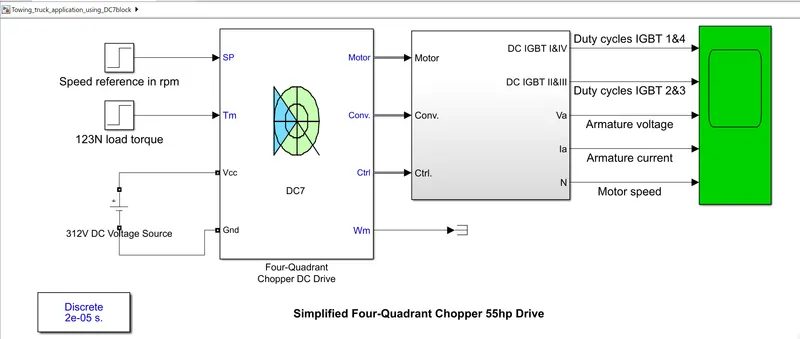
Input voltage: 312V DC
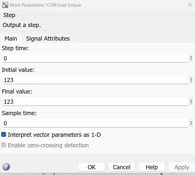
Load torque, Tm: constant load of 123N
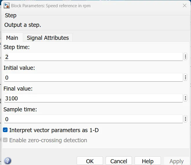
Reference speed: Step signal with initial value zero and final value 3100 rpm
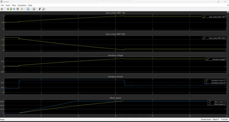
Simulation results:
Observation:
The motor starts from rest and at 2 seconds it starts following the reference speed and catchup the top speed 3100 rpm at 16 seconds. During the simulation period we can observe the transition in the duty cycle of the IGBTs. At top speed or full load, IGBT 1 & 4 is operating at dutycycle 1.
B. Also, Design the parameters in excel sheet.
Ans:
The excel sheet to design parameters is attached along.