Project-1: Powertrain for aircraft in runways
1. Search and list out the total weight of various types of aircrafts.
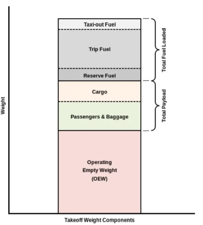
The aircraft gross weight (also known as the all-up weight and abbreviated AUW) is the total aircraft weight at any moment during the flight or ground operation.
An aircraft's gross weight will decrease during a flight due to fuel and oil consumption. An aircraft's gross weight may also vary during a flight due to payload dropping or in-flight re fueling.
At the moment of releasing its brakes, the gross weight of an aircraft is equal to its take-off weight. During the flight, an aircraft's gross weight is referred to as the en-route weight or in-flight weight.
An aircraft's gross weight is limited by several weight restrictions to avoid overloading its structure or to avoid unacceptable performance or handling qualities while in operation.
Aircraft gross weight limits are established during an aircraft's design and certification period and are laid down in the aircraft's type certificate and manufacturer specification documents.
The absolute maximum weight capabilities of a given aircraft are referred to as the structural weight limits. The structural weight limits are based on the aircraft maximum structural capability and define the envelope for the CG charts (both maximum weight and CG limits).
An aircraft's structural weight capability is typically a function of when the aircraft was manufactured, and in some cases, old aircraft can have their structural weight capability increased by structural modifications
2. Is there any difference between ground speed and air speed?
Yes, there is a significant difference between ground speed and air speed and understanding both is crucial in aviation:
Airspeed
Definition:
Airspeed is the speed of an aircraft relative to the air through which it is flying. It determines aerodynamic performance and is measured using an instrument called a pitot-static system.
Types of Airspeed:
Indicated Airspeed (IAS):
The reading directly from the aircraft's instruments, uncorrected for atmospheric conditions.
True Airspeed (TAS):
Corrected for temperature and altitude; represents the actual speed of the aircraft relative to the air.
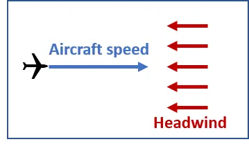
Headwind:
When the wind blows against the direction in which the aircraft moves it is called headwind.
Effects:
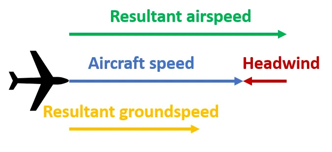
In aerodynamics, flying against the wind at a certain speed is equivalent to flying in calm air at an increased airspeed and reduced groundspeed.
Impact on Operations:
Headwinds impact all phases of the flight
During take-off and landing, headwind increases the airflow, hence the necessary lift is achieved earlier and at lower speeds the wind speed is added to the aircraft speed. As a result, less runway is required to perform a safe take-off or landing. Therefore, headwind is more favorable for these phases of the flight.
A climb or descent in headwind conditions results in an increase of the gradient the level change over the distance travelled even though the rate of climb or descent remains the same. As a result, aircraft reach their cleared levels earlier compared to the calm wind scenario.
In the cruise phase having headwind means increased fuel burn due to the increased drag and increased flight time due to the reduction in groundspeed. Operators try to avoid flying in headwind conditions whenever practicable.
Risks:
While headwinds are beneficial during the take off and the landing phase, underestimating them during the cruise can lead to increased fuel consumption which may lead to the need to divert or reduce the available holding time. In extreme cases fuel exhaustion may occur resulting in forced landing or ditching.
Tailwind:
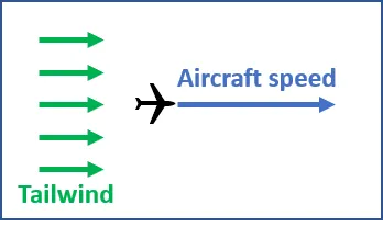
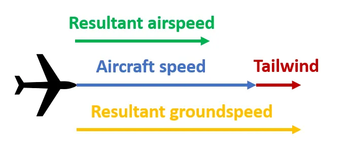
When the wind blows in the same direction as the aircraft moves, it is called tailwind.
Effects:
Flying in tailwind conditions increases the groundspeed and reduces the airspeed of an aircraft.
Impact on Operations:
Tailwinds impact all phases of the flight. This is sometimes beneficial to operations while in other cases it can reduce the available options or create a hazardous situation.
During take-off and landing, tailwinds reduce the airflow. Consequently, the necessary lift is achieved later and at higher speeds (the wind speed is added to the aircraft speed). Therefore, longer runways are required to perform a safe take-off or landing. Another factor to be considered is that in case of rejected take off, the speed of the aircraft will generally be higher, so it will need more distance to decelerate. Take offs and landings with tailwind component exceeding certain value usually 10 kts are avoided the precise value may differ depending on the aircraft type and other factors.
Risks:
The primary risk of tailwind operations is runway excursion. It may happen at take-off especially in reduced take-off thrust scenarios landing especially in the late touchdown case or rejected take-off. In the landing case tailwinds may also result in higher number of go arounds due to the increased probability for an unstable approach. This increases both pilots' and controller’s workload. Additionally landing aircraft would be likely to remain longer on the runway and vacate via later-than-normal taxiways. Therefore, a go around may occur due to insufficient spacing between arriving aircraft.
Katabatic Wind:
A cold flow of air travelling down an orographic slope
Description
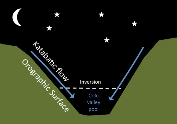
During and after sunset particularly on a clear day night air at and near the top of elevated land surfaces particularly over snow-covered surfaces, cools relatively quicker than air at lower altitudes. As air cools it becomes denser and therefore heavier. The cold air then flows down the side of the mountain, resulting in a katabatic flow or wind.
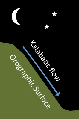
When flying in the mountains, care should be taken when flying on the shady side of valleys as the katabatic effect even during the day may be pronounced depending on performance and type or aircraft.
The colder air which flows down the valley walls may collect at the bottom of the valley creating a cold pool of air near the surface and low temperatures on the ground. La Brevine in Switzerland is noted as having recorded the lowest temperature in Swiss Meteorological record -41.8 oC, mainly due to its situation in a valley surrounded by the Jura mountains in which cold air pools near the valley floor due to the Katabatic effect.
3. Why is it not recommended to use aircraft engine power to move it on the ground at Airport?
Using an aircraft's engines to move it on the ground a process known as taxiing under power is generally avoided in certain cases because of several practical, safety, and economic reasons.
High Fuel Consumption:
Jet engines are optimized for cruising at high altitudes, not for ground operations. Taxiing under engine power consumes significantly more fuel compared to ground-handling alternatives like towing with tugs.
Wear and Tear on Engines:
Prolonged ground operations can lead to unnecessary wear and tear on jet engines. Engines are exposed to debris such as sand stones or other foreign objects on the tarmac which could cause Foreign Object Damage to engine components.
Safety Risks:
Jet engines generate powerful exhaust jet blast and intense suction at the intake. These forces can Blow debris and objects (or even people) behind the aircraft, causing safety hazards. Damage nearby infrastructure ground equipment or other aircraft.
Noise Pollution:
Engines generate significant noise which is undesirable in the vicinity of airports especially near residential or populated areas.
Operational Efficiency:
Using aircraft engines for ground movement can slow down operations. Precision manoeuvres such as parking at the gate or aligning with ground equipment are better performed using a tug which allows more controlled movement.
Environmental Concerns:
Excessive fuel burning during ground operations contributes to higher emissions of greenhouse gases and pollutants which airports aim to minimize.
Aircraft Towing Systems:
Modern airports are equipped with tugs or pushback tractors for ground movement. These are specifically designed to tow aircraft efficiently safely and with minimal fuel consumption.
Some modern aircraft also use electric taxi systems like wheel-mounted electric motors reducing reliance on engines for ground movement.
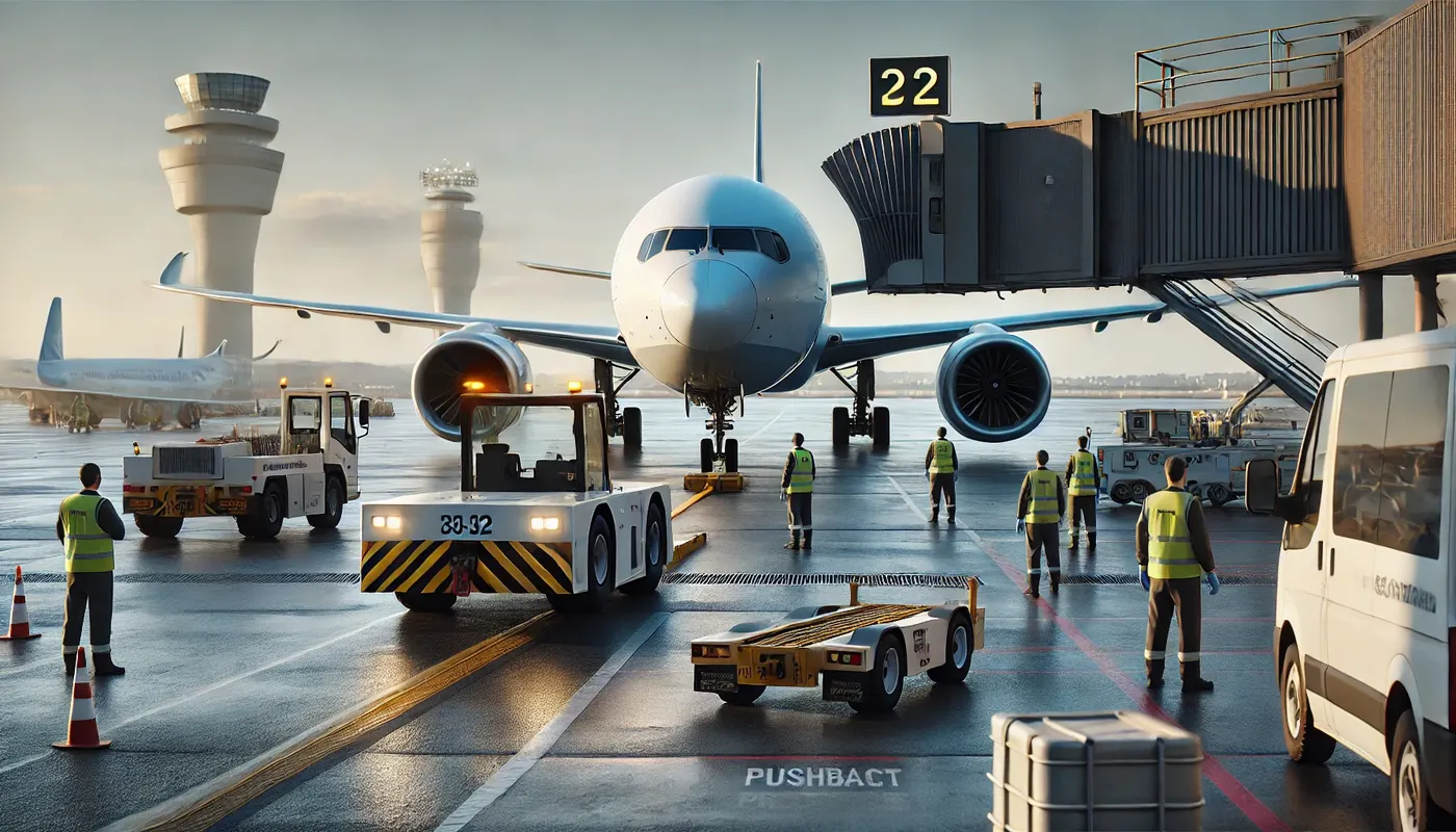
When an aircraft is ready to take off it is usually taxied to the runway using its own engines. However, the process leading to the runway involves coordination and some ground-handling steps before the aircraft becomes self-powered for taxiing.
Pushback:
Pushback means the movement of an aircraft from a nose in parking stand using the power of a specialized ground vehicle attached to or supporting the nose landing gear. It is commonly the second part of a Taxi in Push Out TIPO procedure at airport terminal gates and will be necessary to depart from all except self-maneuvering parking stands unless the aircraft type is capable of power back and local procedures allow this.
Occasionally a pushback may need to be followed by an engines-running pull forward to a position where local procedures allow aircraft to move forward under their own power but usually ground vehicle disconnection will occur after the completion of a pushback.
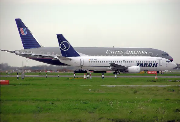
The Procedure:
Once the aircraft commander or other person in charge on the flight deck if the aircraft is not in service has given their confirmation of brakes released to the person in charge of the ground crew who are to carry out the pushback the ground crew become temporarily responsible for the safe manoeuvring of the aircraft in accordance with either promulgated standard procedures or as specifically agreed beforehand.
Unless the manoeuvre is taking place outside the movement area controlled by ATC an RTF clearance to carry it out will be required. Usually but not always, this will be obtained by the aircraft commander or other person in charge in the flight deck. The prescribed RTF phraseology for pushback is contained in ICAO PANS-ATM.
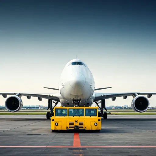
Formerly, almost all aircraft types required that the ground locking pin be installed in the nose landing gear during any pushback however, this is now no longer always the case. If a ground locking pin is installed for the pushback it will need to be removed after the completion of the ground vehicle manoeuvre if the aircraft has been pushed back prior to intended flight.
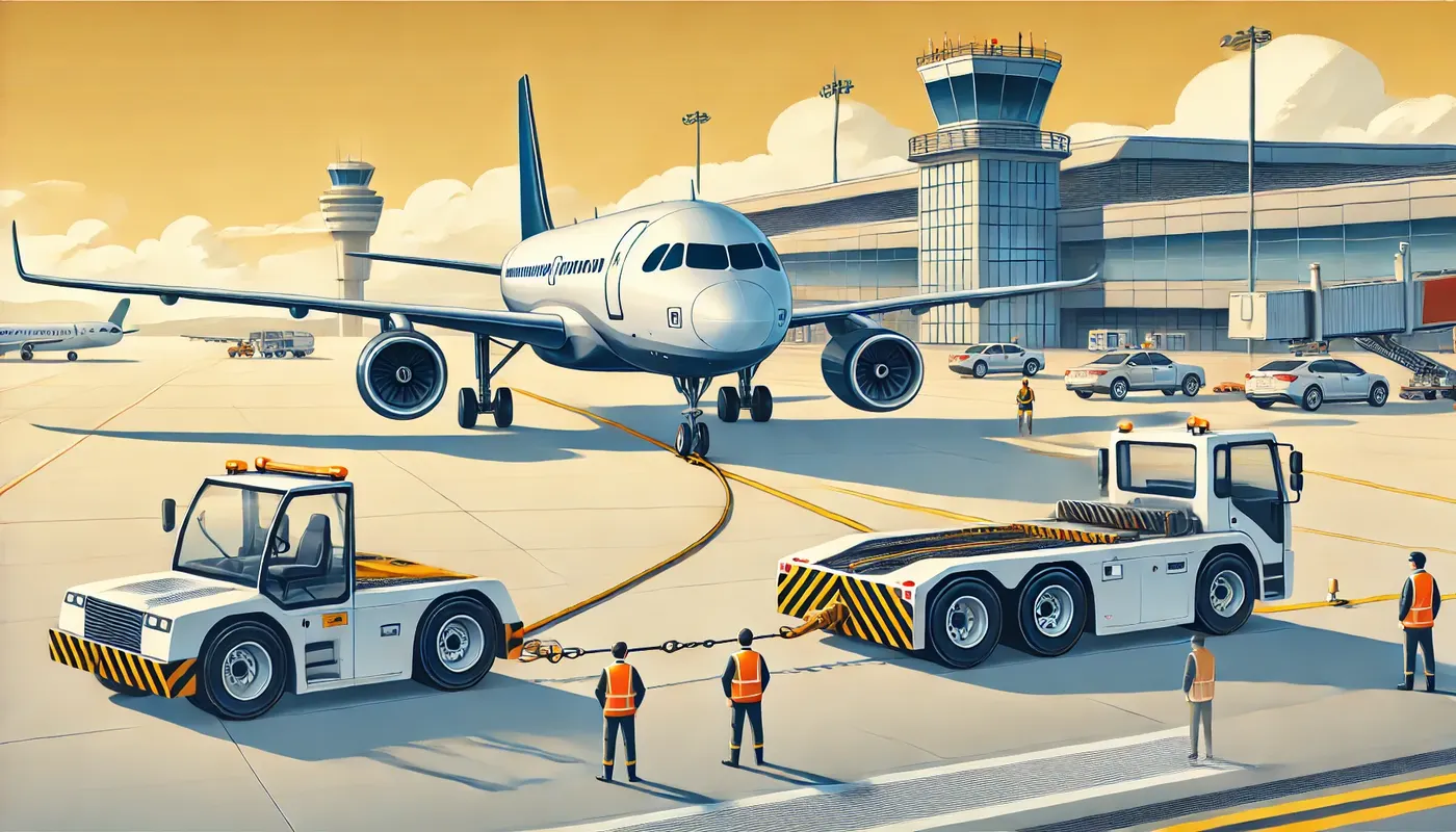
The traditional method of allowing the ground vehicle to move an aircraft is to attach it to the aircraft nose landing gear by means of a towbar. These must be approved for use with a particular aircraft type and clearly marked as such, since there is no universal towbar specification. The same towbar attachment and ground vehicle may also be used for Aircraft Towing in the forward direction.
An alternative method which is becoming more common for pushback is the use of a specialised vehicle called a towbar less tug. This positions two low level arms either side of the aircraft nose landing gear and these are used to engage with the aircraft gear leg and raise it slightly off the ground. These specialized vehicles can also be used to tow aircraft forward Both pushback methods are subject to the observance of any aircraft limits for maximum nose landing gear steering angle but these are not usually especially restrictive.
5. Learn about take-off power, tyre design, rolling resistance, tyre pressure, brake forces when landing.
Take-off power is the phase of flight in which an aerospace vehicle leaves the ground and becomes airborne.
For the aircraft that take off horizontally, this usually involves starting with a transition from moving along the ground on a runway.
The take-off speed requires varies with air density, aircraft gross weight & aircraft configuration.
The power from the engine of the aircraft used to achieve the flight is called take-off power & for light aircraft usually full power is required during take-off, large transport category airliner may use reduced power for take-off where less than full power is applied in order to prolong engine life reduce maintaining cost and reduce noise emissions.
This term is also known as take-off thrust. Pilots use great amount of thrust at take–off to decrease engine wear at take-off. Reduced power is dreaded take-off are normal & frequently used.
The performance is carefully calculated prior to each take-off ensuring proper speed power setting and flaps are used for weight of the take-off on the runway intended & at the proper temperature. When using this method of take-off, it is always possible to increase to full power if the situation requires.
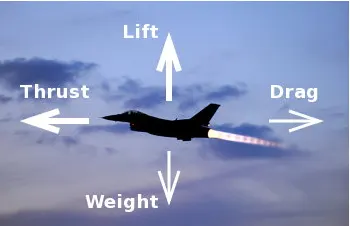
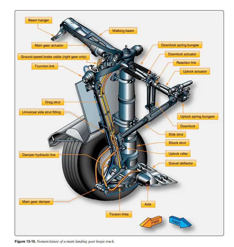
When it comes to safety tyres are one of the most important components of aircraft. They help to absorb the shock of landing and provide cushioning. It also provides the necessary traction for braking and stopping of an aircraft.
An aircraft tyre is designed to withstand extremely heavy loads while landing take off, taxing and parking. The number of wheels required for aircraft increases with the weight of the aircraft as the weight of the airplane needs to be distributed more evenly.
A Boeing 737NG & 737MAX uses 6 wheels, Boeing 787 uses 10 wheels, Boeing 777 uses 14 wheels and Airbus A380 uses 22 wheels. Aircraft tyres work under extreme conditions carrying up to 340 tons and accelerating at over 250 km/hour at take-off in addition to enduring varied environmental stress when in flight and taxiing.
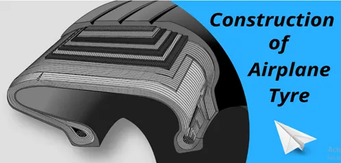
Design and Construction of Aircraft tyre:
I spend too much time at the airfield, sometimes going flying and sometimes just chatting with other idle pilots looking at the maintenance standard of the parked aircraft. Some are well looked after some are not but a common issue that is shared by many is lack of tyre maintenance. Many tyres are under-inflated and worn.
The tyre is a very misunderstood component of the aircraft and as such is being neglected. By looking after it you will be able to extend its life and get more landings for your money. This article was written with reference to Goodyear and Michelin tyre companies maintenance
Tyre Construction:
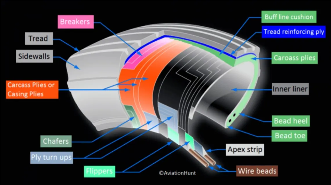
In general tyres are divided into two groups Radial tyres and Bias tyres. Bias ply tyres are constructed with the carcass plies laid at angles between 30º and 60º to the centre line or rotation direction of the tyre. The succeeding plies are laid with the cord at angles that are opposite to each other. This provides balanced carcass strength.
Most aircraft tyres in service today are bias ply tyres. Both the Bias and Radial families have several sub groups according to application and requirements. The group of tyres that will be found on light aircraft and indeed on most piston powered aircraft is Custom III. A typical tyre will be a combination of rubber fabric and steel each material designed to perform a specific task that helps to achieve the required tyre performance.
Some technical aspects of the tyre:
Retreading:
Retreading is methods of restoring a worn tyre by renewing the tread area or by renewing the tread area plus one or both sidewalls. Repairs are included in the tyre retreading process.
Load Rating:
Load rating is the maximum permissible load at a specified inflation pressure.
Ply Rating:
Ply Rating is used to identify the maximum recommended load rating and inflation pressure for a specified tyre. It is an index of tyre strength.
Speed Rating:
The speed rating is the maximum take-off speed to which the tyre has been tested.
Skid Depth:
Skid depth is the distance between the tread surface and the deepest groove as measured in the mould.
Aircraft tyres must have an approved speed and load rating and have sufficient clearance when retracted through landing gear to allow for tyre growth. Tyre growth is the increase in the size of the tyre due to centrifugal forces at high speed.
Key Factors Influencing Rolling Resistance:
Tire Material:
Softer compounds have higher rolling resistance due to increased energy loss during deformation.
Harder compounds reduce rolling resistance but may compromise grip.
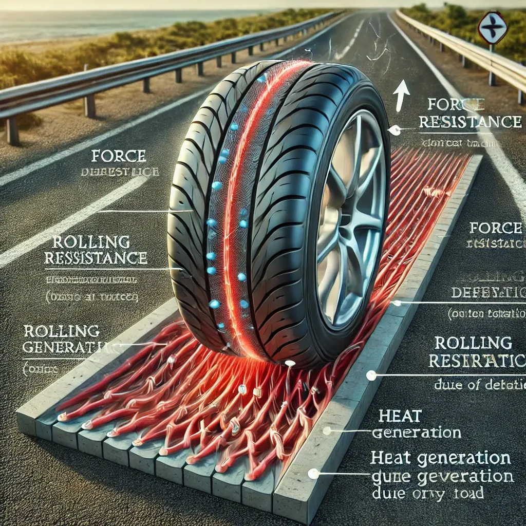
Tire Pressure:
Lower tire pressure increases rolling resistance because of greater deformation of the tire.
Higher tire pressure reduces rolling resistance but may lead to reduced comfort and grip.
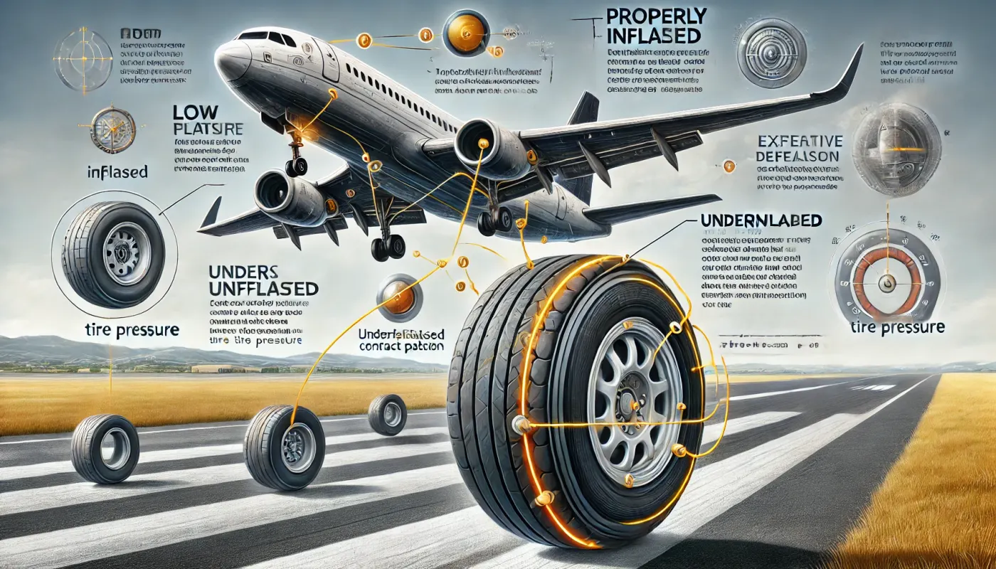
Tire Design:
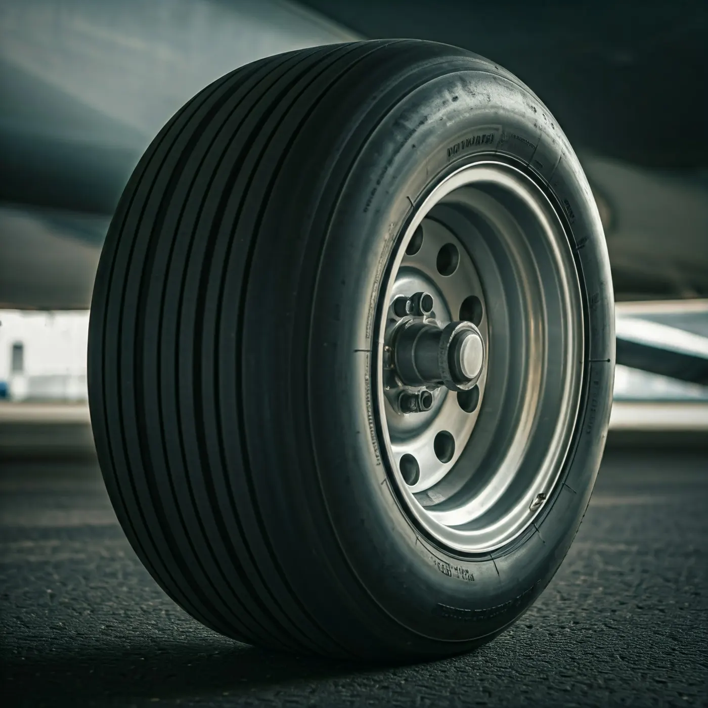
Wider tires tend to have slightly higher rolling resistance due to increased contact area. Narrower tires may reduce rolling resistance but could affect handling and stability. Radial tires typically have lower rolling resistance than bias-ply tires.
Load on the Tire:
An increase in load increases the contact area and deformation, leading to higher rolling resistance.
Speed:
Rolling resistance slightly increases with speed due to higher deformation rates and hysteresis losses.
Surface Conditions:
Smooth hard surfaces produce lower rolling resistance compared to rough or soft surfaces.
Tire Temperature:
Rolling resistance decreases as the tire warms up because the rubber becomes more flexible, reducing energy losses.
Tire Pressure and Brake Forces During Landing:
When an aircraft lands, its tires and brakes play a crucial role in ensuring a safe and controlled deceleration. Here's a detailed explanation of how tire pressure and brake forces interact during this critical phase.
Tire Pressure and Brake Forces During Landing:
When an aircraft lands, its tires and brakes play a crucial role in ensuring a safe and controlled deceleration. Here's a detailed explanation of how tire pressure and brake forces interact during this critical phase.
Tire Pressure:
Optimal Tire Pressure:
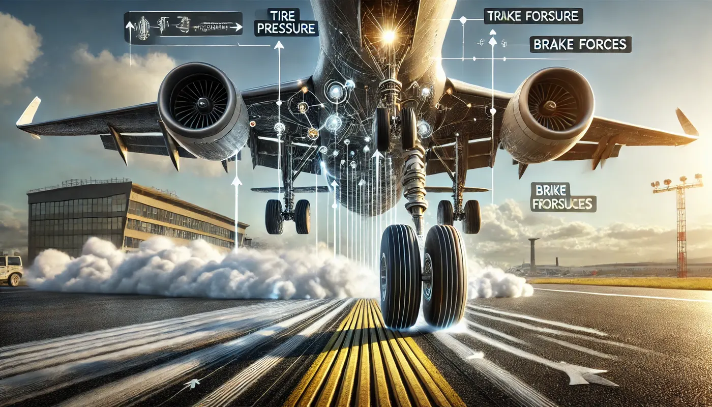
Aircraft tires are inflated to extremely high pressures (often over 200 psi) to handle the massive loads during landing. Proper tire pressure ensures that the tires can absorb shocks resist deformation and provide sufficient contact with the runway.
Effects of Incorrect Tire Pressure:
Low Pressure:
Causes excessive deformation of the tire.
Leads to overheating and increased rolling resistance.
Reduces the ability to support the aircraft's weight effectively.
Can result in tire blowouts or failures.
High Pressure:
Reduces the tire’s ability to absorb shocks, leading to harsher landings. Increases the risk of skidding or hydroplaning on wet runways.
Role During Landing:
Tire pressure directly affects the size of the contact patch which is crucial for braking efficiency and stability.
Properly inflated tires provide optimal grip and reduce the risk of uneven wear or damage during high-speed touchdown.
Brake Forces During Landing:
Components of Brake Forces:
Mechanical Braking:
The aircraft's wheel brakes apply friction to slow the wheels after touchdown. The brake system is designed to withstand the high thermal energy generated during deceleration.
Aerodynamic Braking:
Spoilers and reverse thrust reduce the load on the wheel brakes. These methods complement mechanical braking and improve overall deceleration.
Challenges During Landing:
The high speed and weight of the aircraft create significant braking demands. Brakes must manage forces without overheating or failing under extreme stress.
Anti-Skid Systems:
Modern aircraft use anti-skid systems similar to ABS in cars. These systems prevent the wheels from locking up during hard braking, ensuring maximum grip and avoiding skidding.
Energy Dissipation:
Brakes convert the kinetic energy of the landing aircraft into heat. Advanced materials like carbon composites are used to handle the intense heat and wear during frequent landings.
6. A. With necessary assumptions, calculate the force and power required to push / pull an aircraft by a towing vehicle.
Let us Assume:
Weight of the Aircraft (Boeing 747-8)
=
447,700kg
Rolling Resistance Coefficient of an aircraft tire
= 0.004
Wight of the Tugs Tractor
=
50000kg
Rolling Resistance Coefficient of Towing Vehicle
= 0.0035
Then
Rolling Resistance Force of Tugs Tractor =FRR =
CRR x weight = .0035*50,000*9.81 =1,716.75 N
Rolling Resistance Force of aircraft =FRR = CRR x weight =.004*50,000*9.81
=17,567.748 N
Total Rolling Resistance Force = Rolling
Resistance Force of aircraft + Tugs Tractor = 17.567+ 1.71675
Total Rolling Resistance Force = 19.28 KN
The Aerodynamic Drag is given by
rho= Density of Air Medium
A = Frontal Area of the Vehicle which strike the Air
V = Velocity with the vehicle moves
Cd= Coefficient of Drag which varies different shapes of the frontal area.
Calculation:
Let us assume
The Velocity of the Aircraft while Towing
= 25 KMPH = 6.944 m/s
Density of Air medium
= 1.25 kg/m3
The Frontal area of the Aircraft
= 20 m2
The Frontal area of the Aircraft
= 1.8 m2
The Coefficient of Drag of the Aircraft
= 0.025
The Coefficient of Drag of the Tugs tractor = 1.15
Air drag force = 0.5*rho*A*V^2*Cd
The Air Drag Force of the Aircraft = .5*1.25*20*(6.944^2) *.025 =
15.07 N
The Air Drag Force of the Tugs Tractor = .5*1.25*1.8*(6.944^2) *1.15 = 62.38 N
Total Aerodynamic Drag Force = Air Drag Force of the Aircraft + Air Drag Force of the Tugs Tractor = 15.07 N + 62.38 N
Total Aerodynamic Drag Force = 77.45 N
Therefore, the total force that the motor needs to overcome = Total Rolling Resistance Force + Total Aerodynamic Drag Force = 19.28 + .07745 (KN) = 19.362 KN
Thus, Total Force that the Motor needs to overcome in order to push/pull the Aircraft = 19.362 KN
The Power Required:
The power required by the motor is given by the velocity with which the towing
operation takes place.
The average speed of push/pull = 25 kmph = 6.9444 m/s
Power required by the motor = Total Force*Velocity = 19.362*6.9444
Power Required by The Motor = 134 KW