Project-1: Powertrain for aircraft in runways
Q-1) Search and list out the total weight of various types of aircrafts.
1. LIST OUT THE TOTAL WEIGHT OF VARIOUS TYPES OF AIRCRAFTS:
The aircraft gross weight (also known as the all-up weight and abbreviated AUW) is the total aircraft weight at any moment during the flight or ground operation. An aircraft's gross weight will decrease during a flight due to fuel and oil consumption. An aircraft's gross weight may also vary during a flight due to payload dropping or in flight refueling.
The weights are classified as following:
Maximum design taxi weight (MDTW):
The maximum design taxi weight (also known as the maximum design ramp weight (MDRW)) is the maximum weight certificated for aircraft manoeuvring on the ground (taxiing or towing) as limited by aircraft strength and airworthiness requirements.
Maximum design takeoff weight (MDTOW):
It is the maximum certificated design weight when the brakes are released for takeoff and is the greatest weight for which compliance with the relevant structural and engineering requirements has been demonstrated by the manufacturer.
Maximum design landing weight (MDLW):
The maximum certificated design weight at which the aircraft meets the appropriate landing certification requirements. It generally depends on the landing gear strength or the landing impact loads on certain parts of the wing structure. The maximum landing weight is typically designed for 10 feet per second (600 feet per minute) sink rate at touch down with no structural damage.
Maximum design zero fuel weight (MDZFW):
The maximum certificated design weight of the aircraft less all usable fuel and other specified usable agents (engine injection fluid, and other consumable propulsion agents). It is the maximum weight permitted before usable fuel and other specified usable fluids are loaded in specified sections of the airplane. The MDZFW is limited by strength and airworthiness requirements. At this weight, the subsequent addition of fuel will not result in the aircraft design strength being exceeded.
Manufacuturer's empty weight (MEW):
It is the weight of the aircraft "as built" and includes the weight of the structure, power plant, furnishings, installations, systems and other equipment that are considered an integral part of an aircraft. This excludes any baggage, passengers, or usable fuel.
Pay load:
It is the carrying capacity of an aircraft. It includes cargo, people, extra fuel. In the case of a commercial airliner, it may refer only to revenue-generating cargo or paying passengers.
Operating empty weight (OEW):
It is the basic weight of an aircraft including the crew, all fluids necessary for operation such as engine oil, engine coolant, water, unusable fuel and all operator items and equipment required for flight but excluding usable fuel and the payload.
The total weights of various types of aircraft are shown below;
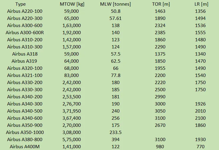
Here MTOW is Maximum Take Off Weight
MLW is Maximum Landing Weigt
TOR is Take Off Run
LR is Landing Run
Q-2) Is there any difference between ground speed and air speed?
When we talk about speeds of aircraft there are two types of speed in aircraft One is the ground speed and other is the air speed.
Ground speed:
It is the airplane's speed relative to earth's surface. One thing that should be noted here is that it’s its horizontal rather than vertical speed – an aircraft climbing completely vertically would have a ground speed of zero.
Air speed:
It is the airplane's speed relative to the air it is flying in. Air speed is what determines whether there is enough airflow around an aircraft to make it fly.
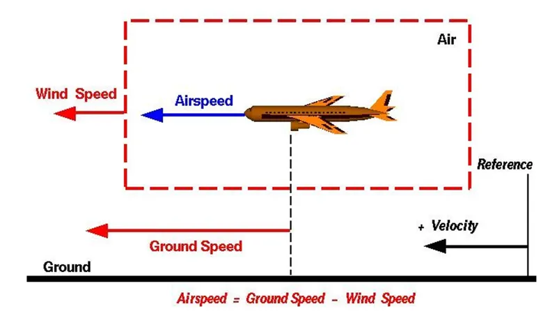
TYPES OF AIR SPEED:
(1). INDICATED AIR SPEED: It's an airspeed that is calculated directly off an aircraft’s pitot-static system. It’s the calculated off the aircraft’s dynamic pressure – the difference between its total pressure and static pressure. The dynamic pressure depends not only on the aircraft’s speed, but also on the density of the air it is flying in. As such, the higher the aircraft flies and the lower the air density as a result the bigger difference between the indicated and true air speed.
CALIBRATED AIR SPEED: It's ben adjusted for variety of errors. For an example, one of the things it’s adjusted for is the flap position. The reason for that is that at different flap positions, air flows differently around the pitot-static system and affects the indicated airspeed readings.
TRUE AIR SPEED: It's been mentioned numerous times the actual speed at which an aircraft is moving relative to the air it is traveling in. It’s calibrated airspeed adjusted for the the exact conditions (altitude, air temperature, etc.) that the aircraft is flying in. While ground speed is the airplane’s speed relative to the surface of the Earth, airspeed – at least true airspeed – is its speed relative to the air it is flying in.
- The aircraft operates on both ground as well as in the air so we need to obsreve how these speeds are related.
- The ground speed and air speed are usually depend on the wind speed.if the wind speed changes these speeds may change.
- if we consider there is no wind speed then the air sped is equal to the ground speed .
- If the wind is flowing in the same direction of the flight then (air speed < ground speed ) so air speed =ground speed -wind speed.
- If the wind is flowing in the opposite to direction of the flight then (air speed > ground speed ) so air speed =ground speed+wind speed.
Q-3) Why is it not recommended to use aircraft engine power to move it on the ground at Airport?
Actually, most of aircrafts can move itshelf in reverse manner by using the reverse thrust technology.But in most of the practical it is not possible because when airplanes start using reverse thrust it will consume lot of fuels as well as causes lot of noise and also hazardous for the people working near by.
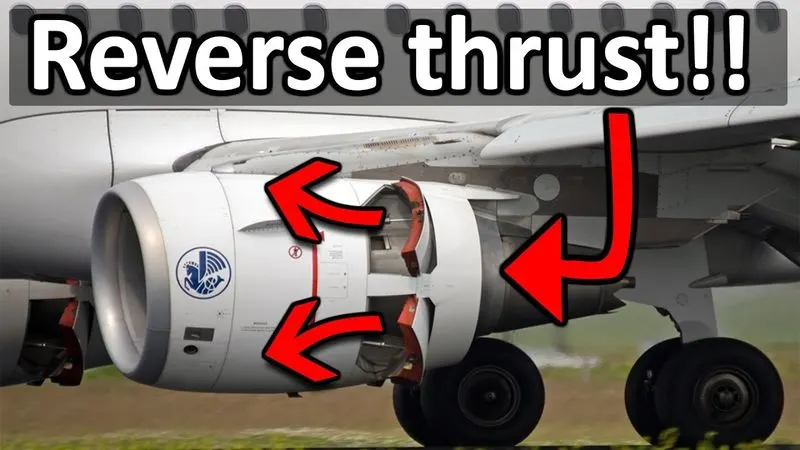
- The another reason for not using the reverse thrust is the plane blast which will cause damage to the big buildings & it's equipement.
- Since the engine is also close to the ground it will blow off the sand and debreis forward and sucks it to the engine and causes damage to it.
- Usage of low power mounted engines have a risk of impurities on the ground may enter inside the engine.
- Loud engines: Thrust reversal involves great forces, and produces an incredible amount of noise. To keep noise pollution to a minimum, we try to avoid roaring jet engines as much possible. An engine running at full thrust would also blow away any loose parts or people on the platform. Some might consider this a safety risk.
- Cleanliness is next to lower maintenance costs: Reversing engine thrust leads to an increase in CO2 production. In addition, thrust reversal can only be used above a certain speed, because otherwise all kinds of dirt will get sucked into the engines. This dirt then causes increased wear and tear of both the engine and the aircraft. All in all, plenty of reasons not to have airplanes taxiing in reverse.
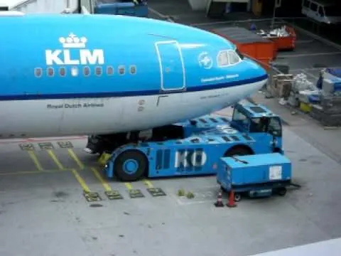
- Back it up!: So how do we move our airplanes backwards? We use a pushback tractor. This special vehicle uses a tow bar, which is attached to the nose wheel of the aircraft. Modern pushback tractors are able to lift the aircraft’s nose wheel, making connecting and disconnecting the tow bar much less time-consuming. Once the tow bar is connected, the tractor is able to push the plane back. Beep, beep, beep – jumbo jet coming through!
- Hence Aircraft engine power is not recommended to move on the ground.
Q-4) How an aircraft is pushed to runway when its ready to take off?
There are two methods are used to push an aircraft into runway when it is ready to take-off. such as:-
- Taxiing
- Towing
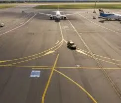
* Taxiing:-
- It is defined as the movement of an aircraft to the ground by it's own power.
- An aircraft moves through wheels on ground the term also used for the air-craft that has skies or floating equipments.
- An aeroplane uses taxiways to move from one place to another place on the same airport.

* Towing:-
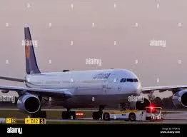
- In case of towing or pushback, an aircraft is moved by a tug.
- Movement of large aircraft about the airport, flight line & hangar is usually accomplished by towing with a tow tractor called as tug.
- A pushback truch lifts the front wheel of the aircraft, their role in most airports is to move the aircraft away from the parking spot on the taxiways.
- Here the truck is removed & when all platform staffs are out of the way, then the engines are started one after another.
- Towing aircraft can be a hazardous operation, causing damage to aircraft & injury to personnel, if done carelessly.
- In the case of small aircraft, some moving parts is accomplished by hand pushing into the correct area of aircraft.
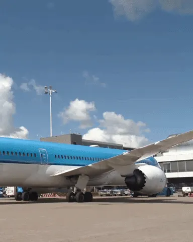
Q-5) Learn about take off power, tyre design, rolling resistance, tyre pressure, brake forces when landing.
TAKE-OFF POWER:
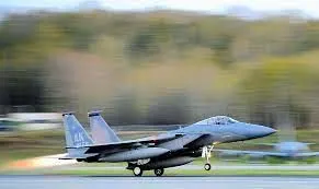
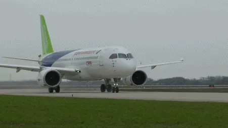
In the case of light aircraft full power is used during take-off and in large aircrafts like airliner use a reduced level power to take-off,where less than full power is used to prolong the engine durability. before take-off the piston engines are run routinely at high power to check engine related problems.The nose is raised to a nominal 5-15 degree nose up pitch alltitude toincrease lift from the wings and effect lift off. The takeoff power is controlled in such a way that it can cover 35 feet screen height plays in the take-off. The pilot needs to look around different distances that affect the take-off performance which are:
- TAKE-OFF RUN AVAILABLE(TORA): The distance from which the air-craft can start its take-off run to the point till the end marking for surface change.
- THE CLEARWAY: This is the area st the end of TORA that is free from buildings trees or any other obstructions .The aircraft can use this area to acheive 35 feet sceen height.
- ACCELERATE-STOP DISTANCE AVAILABLE(ASDA): The final distance that must be considered for take-off performance is the ASDA, This distance of weight bearing surface is available to the air-craft to accelerate and then come to stop in case of emergency.
- Take-off power= Force*Displacement i.e (m*dv/dt)*2*S1=> (T-D-F)*S1, where S is the runway length. The forces involved are T= thrust of propulsion system, D= Aerodynamic drag which the vehicle resists, F= rolling resistance due to the contavt on wheels on the ground
TIRE DESIGN:
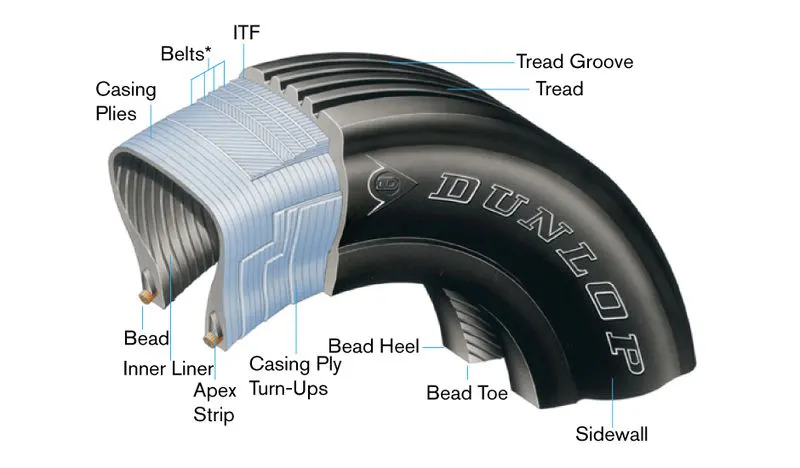
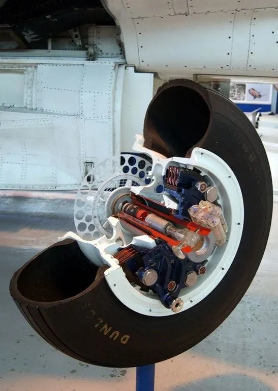
The tire design of an aircraft may seem a challenging job, because the tyre has to withstand heavy loads while landing, take-off, taxiing and parking. The number of wheels required for an aircraft increases as the weight of the aircraft increases cause it should be distributed evenly. The tyre generates a lot of heat during landing because it drags the wheel to match its momentum. The tyre is designed in such away that it withstands hugh crosswind conditions, extreme pressure and to prevent hydroplanning and for increased braking effect.
There are two types of construction of tyres which are :
Radial tyre: It has fiber strands of the poly fabric at 90degree to the direction of rotation and the tyre side-wall. This restricts flexibility of the bi-deirectional sidewall while it strengthnes the tyre to carry heavy loads . Due to their unique construction radial tyres are resistant to penetration and cuts. Due to stiffer threads they distribute weight evenly. Thus provide greater traction and helps in preventing heat.
Bias tyre: It has the fabric bias oriented with and cross the direction of rotation and the side-wall. Since the fabric stretches, the tire is flexible and can absorb loads, the cut resistnt area is the sidewalls, strength is obtained by adding piles, these tyres doesn't absorb heat well.
Rolling resistance:
It is defined as the force resisting the motion when a body rolls on a surface (ex- ball, tyre) .Rolling resistance can be seen in an aircraft when the air-craft takes off from the runway and while landing on the runway.
rolling resistance force can be written as: Frr=Urr*m*g(N)
Where Urr= coefficient of rolling resistant
m= Mass(kg)
Frr= rolling resistance (N)
g= acceleration due to gravity(9.81m/s^2)
Tyre pressure:
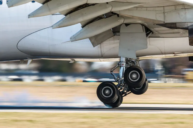
The tyres of an air-craft have to withstand very high amounts of pressure, while take-off, landing, towing, taxing. as the weight of the aircraft increases the no. of wheels are also increased.as we know that while landing the aircraft drags the wheel till it matches with its rotational velocity, due to this a lot of heat is generated due to friction. aircraft tires are usually filled with nitrogen to minimize expansion and contraction from changes in tempretures and pressure during flight , Also the use of inert gasses for tire inflation reduces the possibility of tire explosion. services should be done regularly by checking tyre pressures and maintaining proper tire inflation pressure.Rolling resistance and tire pressure are inversely proportional to each othe
- Airplane tires are designed to withstand a wide range of operating conditions, including carrying very high loads and operating at very high speeds.
- It is common for a jet airplane tire to carry loads as heavy as 60,000 pounds while operating at ground speeds up to 235 miles per hour.
- Generally,a aircraft tyre can handle upto 38 ton load.
- It can meet the grounds 500 times before needing a re-tread, a refresh it can take on seven times in it's life.
Brake devices used during landing:
- Wheel brakes(Anti-skid and Auto-brakes): Aircraft have highly-engineered, multi-disc brakes made of a carbon-steel material. Manufacturers include Honeywell and Goodrich, part of Collins Aerospace. In general, the brakes are composed of discs that rotate with the wheel and separate discs that are fixed. When pressure is applied from the right fixed disc on all of the discsthe entire assembly compresses to create the braking action. Carbon brakes are standard today; they cool faster than steel brakes (their predecessor) and can weigh up to 700 pounds less. For the initial part of the braking, say down to around 70 knots, we let the autobrakes do the job, but after that we have to come onto the toe brakes to disengage the autobrake The transition from autobrake to manual brakes can be quite difficult to do smoothly especially in a crosswind, as you will be steering the aircraft with the rudder pedals and then have to press down on the tops of the rudder pedals evenly to deactivate the autobrakes and start manual braking
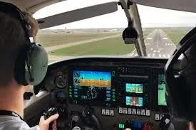
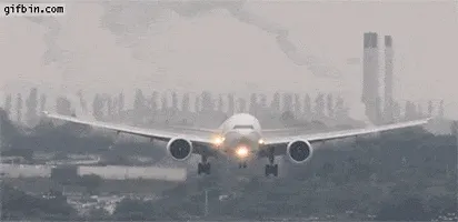
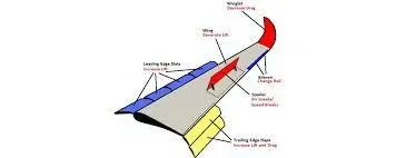
- Spoilers: when the wheels touch the ground, a set of spoilers raise up quickly, which kills the lift provided by the wings. (There are two sets seen in the image below: ground spoilers that only deploy on landing, and spoilers that are used in flight as speed brakes as well as on landing.) While the spoilers provide some drag, their primary purpose is to stop the plane from actually flying, putting all of the weight on the landing gear and in turn making the brakes that much more effective.
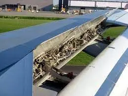
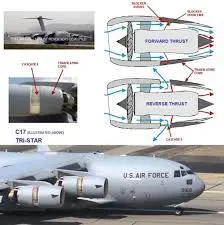
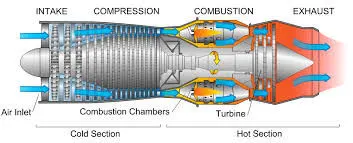
- Reverse thrust: he final element of braking action is the thrust reversers. In a modern high-bypass turbofan engine, a full 90 percent of the air passing through the engine is simply sucked in, sped up and pushed out of the engine without mixing the fuel. In these engines, ducts on the side of the engine open up and direct that air out and nearly forward, opposite the direction of travel. This is called a cold-stream reverse thrust, and is part of the engine design of most modern engines. (You may have also seen clam-shell style reverse thrusters on older aircraft, which cup the back of the engine.)
Q-6) A. With necessary assumptions, calculate the force and power required to push / pull an aircraft by a towing vehicle.
Let us assume;
Antonov An-225 Mirya
Mass of aircraft M1 = 285,000kg
Mass of Towing vehicle M2 = 50,000kg
Coeffiecient of rolling resistance for dry concrete road, µrr = 0.04
Frontal area of aircraft, A = 355m^2
Drag coefficient of an aircraft, Cd = 0.6
Drag coefficient of a towing vehicle, Cd = 0.15
Density of air =1.225kg/m^3
G = 9.81
Speed of an aircraft V =20 * (5/18) = 5.556 m/sec
ROLLING RESISTANCE FORCE:
For aircraft:
Frr = µrr * m * g
Frr = 0.04* 285000 * 9.81
=111834 N
For Towing Vehicle:
Frr = µrr * m * g
= 0.04*50,000 * 9.81
=19620N
We need to add the rolling resistance of both towing vehicle and aircraft.
Frr = Frr (aircraft) + Frr (vehicle)
Frr = 111834+19620
Frr = 131454N
AERODYNAMIC DRAG FORCE:
Fad = (0.5) * ρ * V^2 *(Cd (aircraft) + Cd (vehicle))
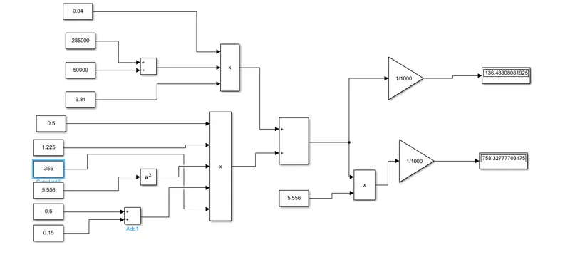
= (0.5) * 1.225 * 355 * (5.556)^2 *(0.6 + 0.15)
= 5034.05N
Total force of the towing vehicle,
F = Fad + Frr (vehicle) + Frr (aircraft)
F = 5034.05+ 111834+19620
= 136488.05 N
POWER REQUIRED:
P = F * V
= 136488.05 * 5.556
= 758327.606 W
The force and power of the towing vehicle carrying the aircraft are 136.488 KN and 758.327 KW respectively.
B. Develop the model for the calculated force and power using Simulink:
Q-7) A. Design an electric powertrain with type of motor, it’s power rating, and energy requirement to fulfill aircraft towing application in Simulink. Estimate the duty cycle range to control the aircraft speed from zero to highest. Make all required assumptions. Prepare a table of assumed parameters. Draw a block diagram of powertrain.
(Hint :DC7 Block)
Block Diagram of Powertrain:-
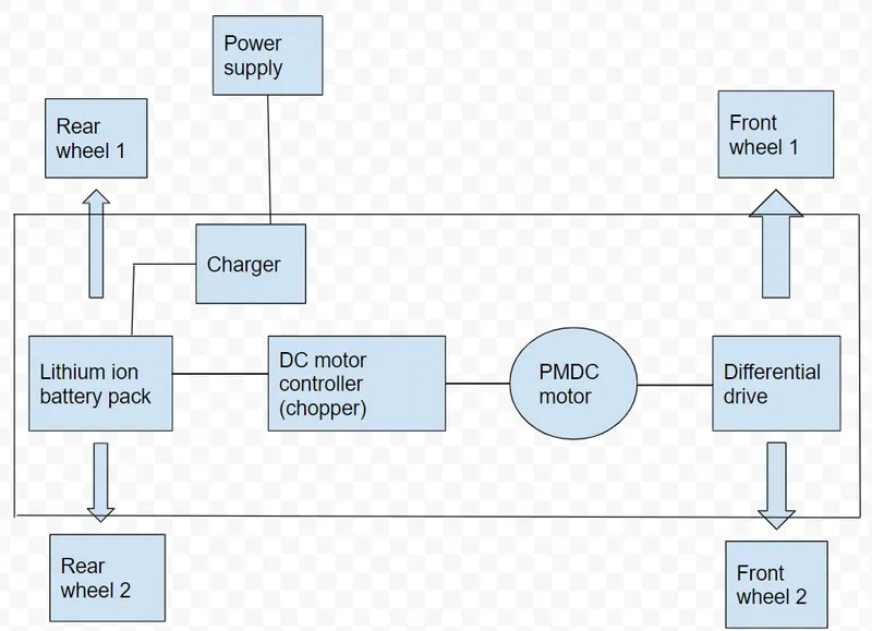
- The above block diagram represents the Powertrain blockset of towing vehicle which are used to push or pull an aircraft.
- From the diagram, we can see that there are 4 wheels (2 Front wheels & 2 Rear wheels).
- The battery pack is Lithium ion battery pack which are used to provide sufficient electrical power to different parts such as Motor, Controller,auxillary battery etc.
- Power supply is connected with the lithium ion battery pack through charger.
- then after getting charged, the battery pack will provide power to the controller which will control the operation of different parts inside the vehicle.
- Then There is a DC motor controller (Chopper) is connected with battery pack which will provide sufficient power to the Motor according to the rating of motor.
- Then a differential drive which carries the wheels is connected with the motor.
- then when motor starts to rotate then wheels also starts to rotate by the help of these transmission system
Based on previous question,
Force required to push/pull the aircraft = 136.488 KN
Power required is = 758.327 KW
Let us assume the radius of the tyre as = 25 inches = 0.635m
Gear ratio = 8
Transmission efficiency (et) = 87%
Motor efficiency (em) = 95%
Then,
Torque required for the wheel (Tw) = Total force * Radius in meters
=136.488 * 0.635m
= 86.669KNm
Motor torque = wheel torque / (Gear ratio * et)
= 86.669 /(8 * 0.87)
=13.374 KNm
The required motor torque = 13.374/ 0.95
=14.078
The total power required by the motor considering all efficiencies = 758.327 /(0.87 * 0.95)
=917.516KW
Let us assume the towing operation is done for 15 minutes (0.25 hrs)
Total energy consumed = 917.516* 0.25
=229.379 Kwh
Duty cycle (d ) = (Required power)/ (Rated power)
= 917.516 / 950 = 0.965
= 96.5%
Thus the duty cycle range to control the aircraft speed from zero to highest is 0 to 96.5% .
* Therefore controller will provide range of duty cycle from 0% to 96.5% to control the towing speed.
Simulink Model:-
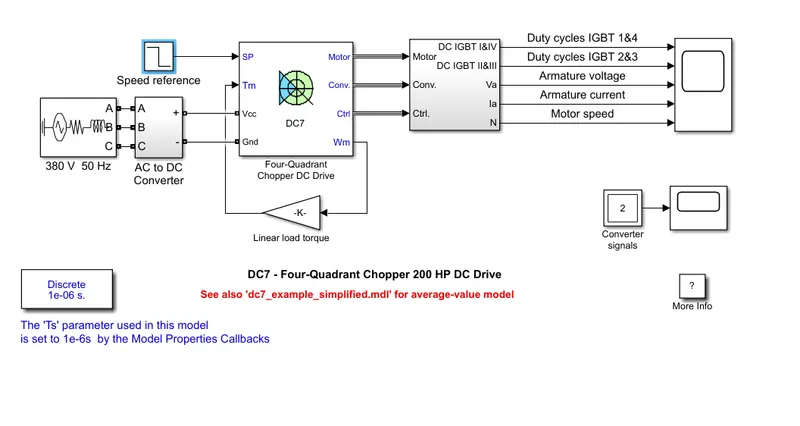
- The above model consists of 3-phase source of 380V 50 Hz rating, an AC to DC converter, a Four-quadrant Chopper DC drive, speed reference, gain block (Linear load torque),Selector subsystem, powergui & a scope.
- The 200 HP DC motor is separately excited with a constant 150 V DC field voltage source.
- The armature voltage is provided by an IGBT converter controlled by two PI regulators.
- The converter is fed by a 515 V DC bus obtained by rectification of a 380 V AC 50 Hz voltage source.
- In order to limit the DC bus voltage during dynamic braking mode, a braking chopper has been added between the diode rectifier and the DC7 block.
- The first regulator is a speed regulator, followed by a current regulator.
- The speed regulator outputs the armature current reference (in p.u.) used by the current controller in order to obtain the electromagnetic torque needed to reach the desired speed.
- The speed reference change rate follows acceleration and deceleration ramps in order to avoid sudden reference changes that could cause armature over-current and destabilize the system.
- The current regulator controls the armature current by computing the appropriate duty ratios of the 5 kHz pulses of the four IGBT devices (Pulse Width Modulation).
- For proper system behaviour, the instantaneous pulse values of IGBT devices 1 and 4 are opposite to those of IGBT devices 2 and 3.
- This generates the average armature voltage needed to obtain the desired armature current.
- In order to limit the amplitude of the current oscillations, a smoothing inductance is placed in series with the armature circuit.
- Before starting the simulation, set the initial bus voltage to 515 V via the GUI block ('Initial States Setting' button and 'Cbus' variable).
- Start the simulation. You can observe the motor armature voltage and current, the four IGBT pulses and the motor speed on the scope. The current and speed references are also shown.
- The motor is coupled to a linear load, which means that the mechanical torque of the load is proportional to the speed.
- The speed reference is set at 500 rpm at t = 0 s. Observe that the motor speed follows the reference ramp accurately (+400 rpm/s) and reaches steady state around t = 1.3 s.
- The armature current follows the current reference very well, with fast response time and small ripples. Notice that the current ripple frequency is 5 kHz.
- At t = 2 s, speed reference drops to -1184 rpm. The current reference decreases to reduce the electromagnetic torque and causes the motor to decelerate with the help of the load torque.
- At t = 2.2 s, the current reverses in order to produce a braking electromagnetic torque (dynamic braking mode). This causes the DC bus voltage to increase.
- At t = 3.25 s, the motor reaches 0 rpm and the load torque reverses and becomes negative. The negative current now produces an accelerating electromagnetic torque to allow the motor to follow the negative speed ramp (-400 rpm/s). At t = 6.3 s, the speed reaches -1184 rpm and stabilizes around its reference.
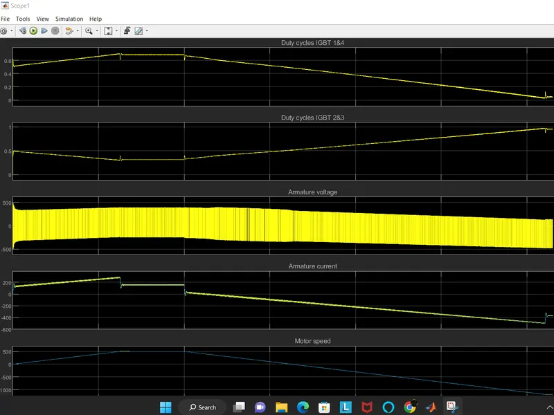
- From the scope result, we can see that when two IGBTs 1 & 4 are ON then armature fluctuated more with higher amplitude means high value of armature voltage.
- at that time, the armature cure current remains +ve which states that motor is in loaded conditions.
- Motor speed also increases & +ve.
- then when 2 & 3 IGBTs are ON, then armature voltages flactuate but with lower amplitude so we can say that voltage value becomes low.
- at that time, armature currents starts decreasing & becomes -ve which states that motor is in either charging or in regenerative conditions.
- Speed also become -ve which states that it motor charges it's direction of rotating & acts as generator.
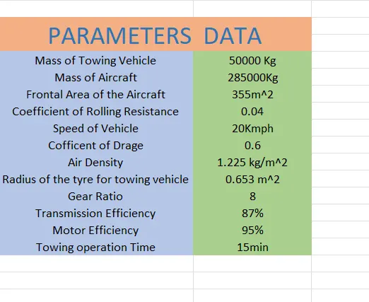
B. Also, Design the parameters in excel sheet.
CONCLUSION:-
- Search and list out the total weight of various types of aircrafts is done.
- Difference between ground speed and air speed is explained.
- cleared that it not recommended to use aircraft engine power to move it on the ground at Airport.
- An aircraft is pushed to runway when its ready to take off is illustrated.
- Learn about take off power, tyre design, rolling resistance, tyre pressure, brake forces when landing are completed.